Introduction
The Numato Lab XO-Bus Lite is a framework for communicating with Numato Lab boards such as Saturn, Neso, Skoll, Styx etc from a host. XO-Bus Lite accelerates the development by providing an intuitive way of transferring data into and out of the FPGA. The XO-Bus Lite framework acts as a standard AXI4 Memory Mapped Master, and it can control AXI4 compliant slaves and use existing AXI4 infrastructure provided by Xilinx Vivado. This feature itself makes XO-Bus Lite Framework very powerful. Users can use most, if not all, IP cores that support AXI interface and read/write to memory and memory mapped registers on the devices directly from host PC. There is no need for any microprocessor (such as Microblaze), though XO-Bus Lite can also work alongside Microblaze or any other AXI Master. This gives users a high degree of flexibility in their designs. This article will demonstrate how to use XADC Wizard IP core with XO-Bus Lite to read FPGA temperature and voltages using Python.
Prerequisites
Hardware
- Neso, or Skoll, or Styx
- Xilinx Platform Cable USB II (optional)
Software
- Xilinx Vivado Design Suite 2017.4 or higher
- FTDI FT Prog Utility
Familiarity with the Vivado Design Suite and its IP Integrator flow and XO-Bus Lite is also necessary to follow this article.
The article uses Neso Artix 7 FPGA Module for illustrating the steps, but similar steps are applicable for Skoll Kintex 7 FPGA Module and the Styx Zynq FPGA Module.
Download and install Vivado Board Support Package files for the Numato Lab boards from here. Follow the README.md file on how to install Vivado Board Support Package files for Numato Lab boards.
Let’s get started
Step 1
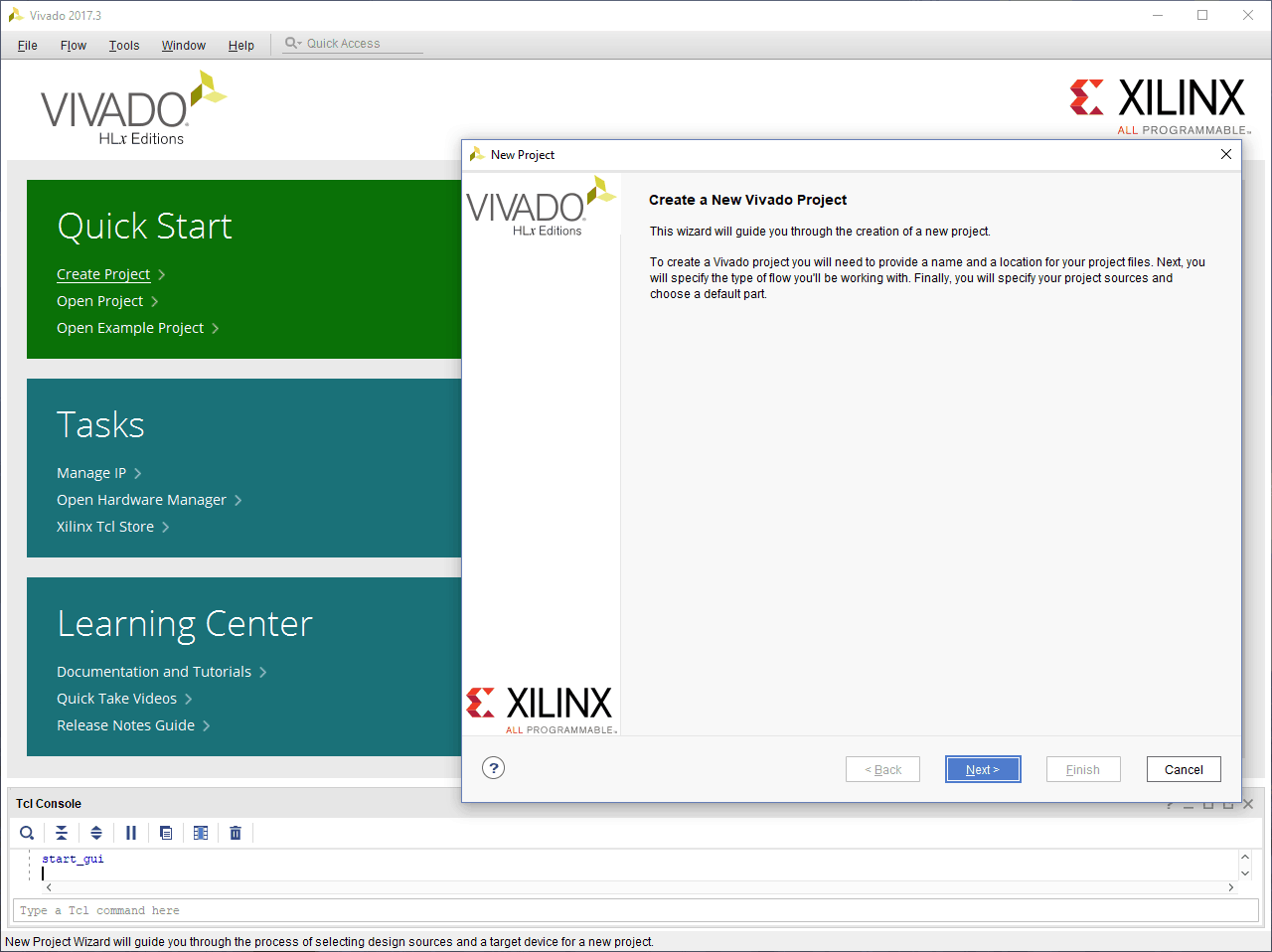
Open Xilinx Vivado Design Suite. Go to “File -> “New Project…”. The “New Project” wizard will open. Click “Next”.
Step 2
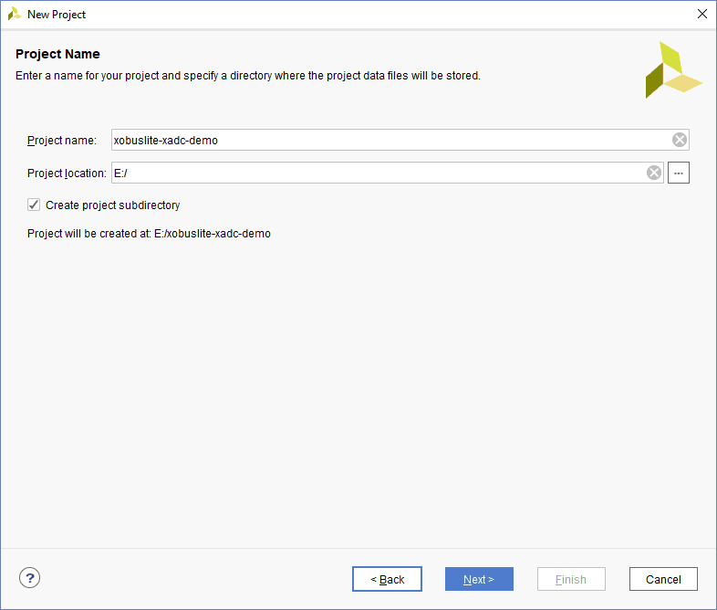
In the “Project Name” step of the “New Project” wizard, enter a name for the project and select a location of your choice. Click “Next”.
Step 3
In the “Project Type” step of the “New Project” wizard, select the type as “RTL Project”, select “Do not specify sources at this time” and click “Next”.
Step 4
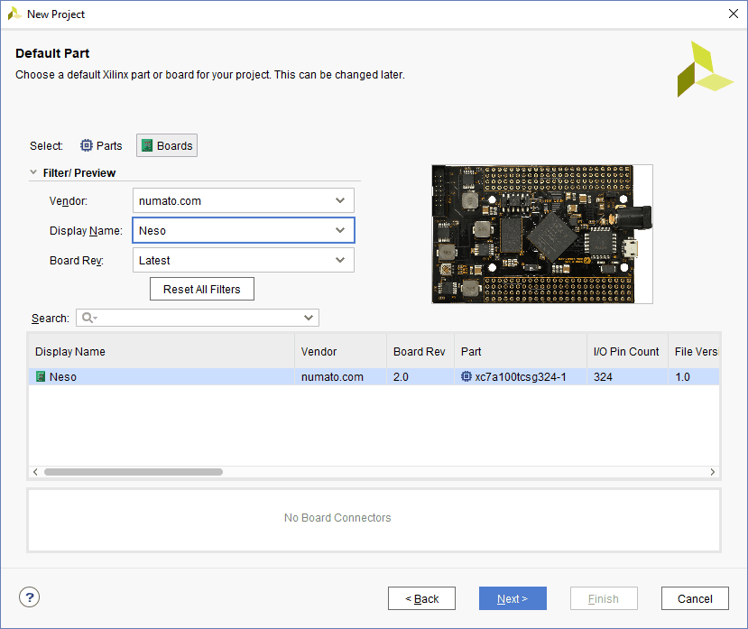
In the “Default Part” step of the “New Project” wizard, go to “Boards” tab and select Vendor as “numato.com” from the list. Select Neso, or Skoll or Styx as applicable. That is, if you are using Styx for following this article, select Styx from the list. If Neso, Skoll and Styx are not listed, make sure board support files are installed correctly. Click “Next”.
Review the project configuration in the “New Project Summary” page and finally click “Finish”. A new Vivado project will be created with the selected project options.
 |
 |
Step 5
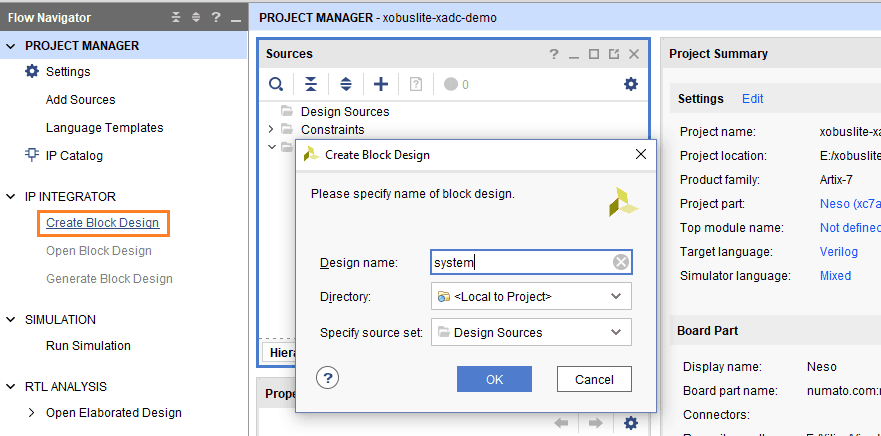
Go to “Flow Navigator” on the left side of Vivado window and click “Create Block Design” under “IP Integrator” section. Enter a name for the block design and click “OK”.
Step 6
The XO-Bus Lite IP repository needs to be added to Vivado so that XO-Bus Lite can be used with Vivado’s IP Integrator.
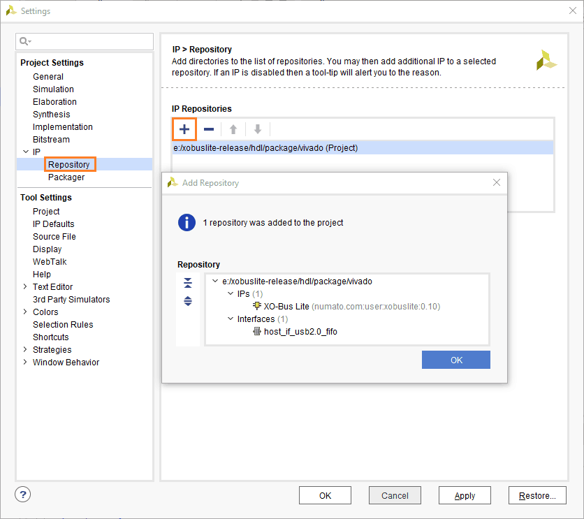
Go to “Settings” under “Project Manager”. In the “Settings” dialog window, go to IP -> Repository page and click “+” icon. Browse to the location of the XO-Bus Lite IP Package and click “Select”. Vivado will scan for IPs available in the selected location and display the confirmation that it found 1 IP and 1 interface in the selected repository. Click “OK” to close the confirmation dialog window. Again click “OK” to close the “Settings” configuration window.
Step 7
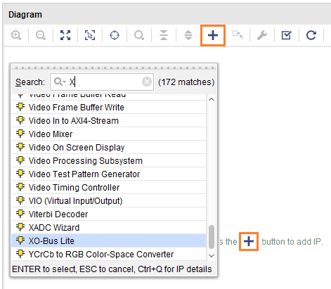
Click “+” icon on the toolbar of the Block Design Diagram Window. Search for XO-Bus Lite from the list and double click to add XO-Bus Lite IP to the block design.
Step 8
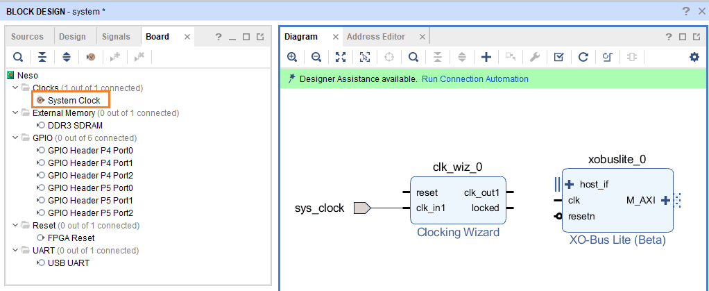
From the “Board” tab of the Block Design window, drag and drop “System Clock” into the block design.
Step 9
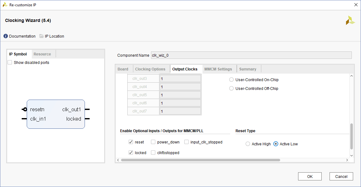
Double-click the “Clocking Wizard” IP block, go to “Output Clocks” tab and select “Reset Type” as “Active Low”. Click “OK” to close the IP customization window.
Step 10
Similar to as in Step 7, add “XADC Wizard” IP core to the block design. Click “Run Connection Automation” from the green bar on top of the block design. Select “All Automation” in the “Run Connection Automation” dialog window as shown below and click “OK”. Vivado should automatically connect the blocks.

Step 11
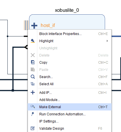
Right-click on the “host_if” port of the XO-Bus Lite IP block and click “Make External”. Rename the external port back to “host_if” in case Vivado appends any extra characters in its name (such as “host_if_0”).
Step 12
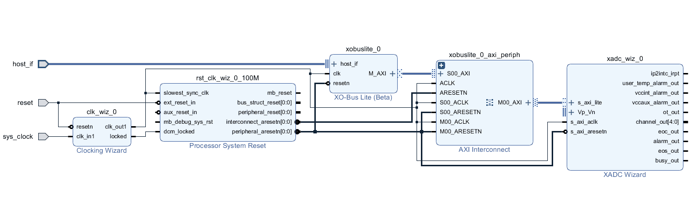
Run connection automation once again to connect “ext_reset_in” port of “Processor System Reset” to the external reset port. Regenerate the layout to make it cleaner. The final block diagram should look something like this:
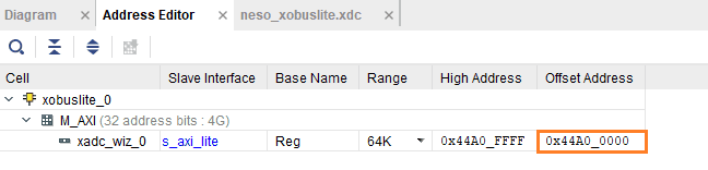
Change to “Address” tab in the block design window and note down the base address of XADC Wizard IP core. This address will be used for the variable XADC_BASEADDR in the Python test code xobus_xadc.py in the last step of this article.
Step 13
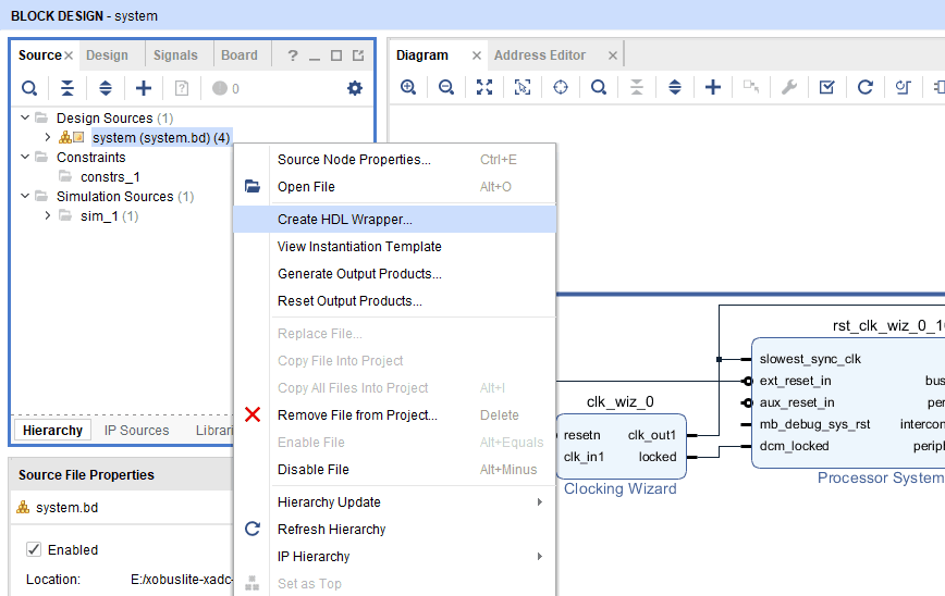
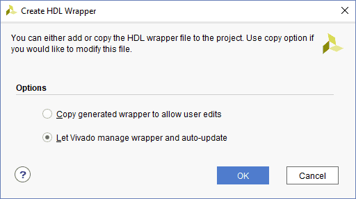
Save the block design. Go to the “Source” tab in the “Block Design” window and right-click on the “system” block design. Select “Create HDL Wrapper…” from the context menu as shown below
Opt to “Let Vivado manager wrapper and auto-update” and click OK.
 Step 14
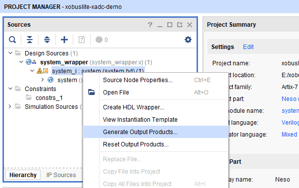
Once more, right-click on the “system” block design and select “Generate Output Products…”.
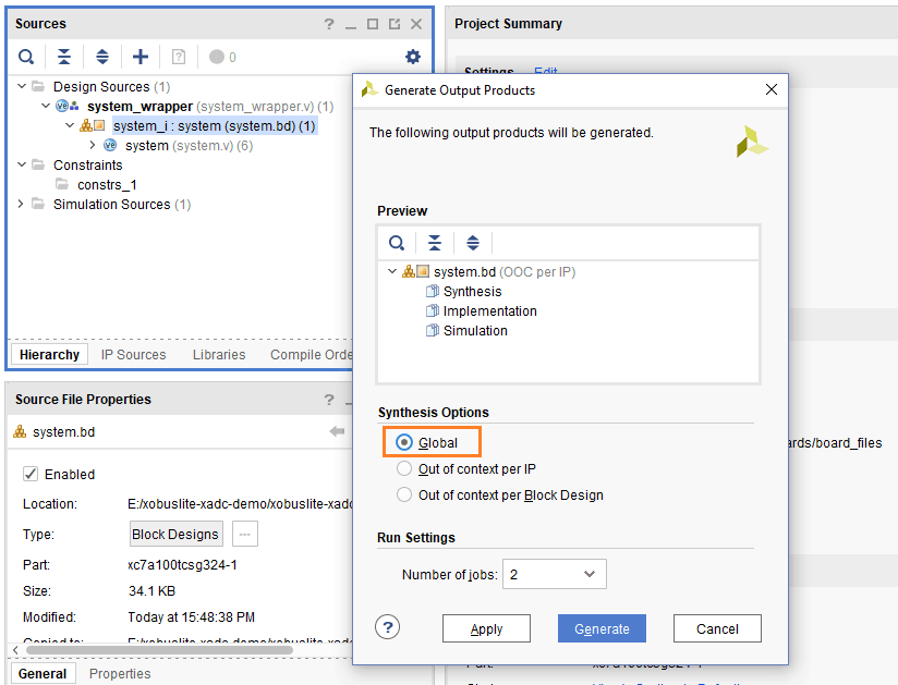
In the “Generate Output Products” dialog window, select “Global” synthesis option. This step is important. Click “Apply” and then “Generate”.
Step 15
Right-click “Constraints” in the Sources section and select “Edit Constraints Sets…”

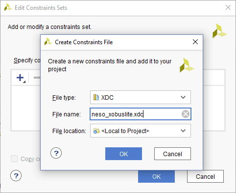
Click “Create File” in the “Edit Constraints Sets” dialog window.
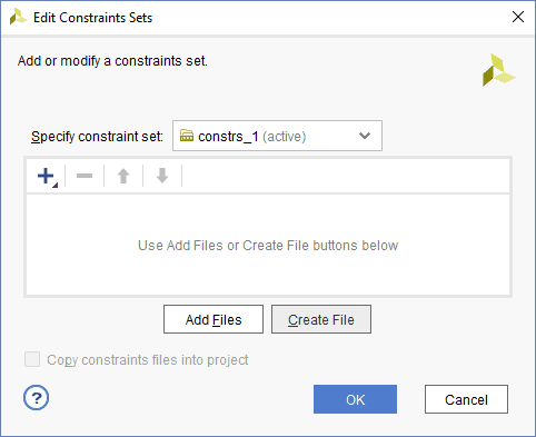
Enter the file name of the constraints file as “neso_xobuslite.xdc” and click OK twice.
Step 16
Open the newly created constraints file “neso_xobuslite.xdc” in the Vivado editor and copy-paste following contents into it. Save the constraints file. If you are using Skoll or Styx instead of Neso to follow this article, change the constraints correspondingly.
set_property -dict {IOSTANDARD LVCMOS33 PACKAGE_PIN J18} [get_ports {host_if_data[7]}]
set_property -dict {IOSTANDARD LVCMOS33 PACKAGE_PIN J17} [get_ports {host_if_data[6]}]
set_property -dict {IOSTANDARD LVCMOS33 PACKAGE_PIN G18} [get_ports {host_if_data[5]}]
set_property -dict {IOSTANDARD LVCMOS33 PACKAGE_PIN F18} [get_ports {host_if_data[4]}]
set_property -dict {IOSTANDARD LVCMOS33 PACKAGE_PIN E18} [get_ports {host_if_data[3]}]
set_property -dict {IOSTANDARD LVCMOS33 PACKAGE_PIN D18} [get_ports {host_if_data[2]}]
set_property -dict {IOSTANDARD LVCMOS33 PACKAGE_PIN B18} [get_ports {host_if_data[1]}]
set_property -dict {IOSTANDARD LVCMOS33 PACKAGE_PIN A18} [get_ports {host_if_data[0]}]
set_property -dict {IOSTANDARD LVCMOS33 PACKAGE_PIN K16} [get_ports host_if_txe_n]
set_property -dict {IOSTANDARD LVCMOS33 PACKAGE_PIN G13} [get_ports host_if_rxf_n]
set_property -dict {IOSTANDARD LVCMOS33 PACKAGE_PIN M13} [get_ports host_if_wr_n]
set_property -dict {IOSTANDARD LVCMOS33 PACKAGE_PIN D9 } [get_ports host_if_rd_n]
Step 17
Click “Generate Bitstream” under “Program and Debug” section of Flow Navigator. Let Vivado automatically synthesize and implement the design as prerequisites for generating bitstream

Step 18
Make sure that Channel/Port B of FT2232 on Neso is configured as 245 FIFO. If in doubt, follow the steps under “Driver Installation” section of the article “Getting Started with XO-Bus Lite Framework” to configure Neso correctly for XO-Bus Lite. Once the bitstream is generated, program the bitstream to Neso using JTAG or Neso Configuration Tool.
Step 19
Browse to xobuslite-release\sdk\msvc\lib\amd64 and copy xobus-lite.dll. Create a new folder named bin inside xobuslite-release\sdk and paste the DLL in that folder. The final path of the DLL should be xobuslite-release\sdk\bin\xobus-lite.dll.
Step 20
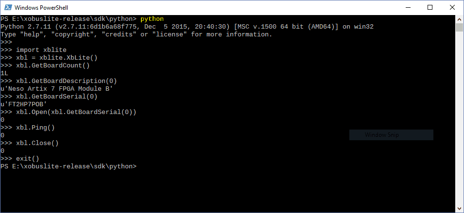
Open Command Prompt or PowerShell in the folder xobuslite-release\sdk\python and run python from this folder. Try following commands in the python. If any of the below commands give error, it means the XO-Bus isn’t set up correctly.
>>> import xblite
>>> xbl = xblite.XbLite()
>>> xbl.GetBoardCount()
1L
>>> xbl.GetBoardDescription(0)
u'Neso Artix 7 FPGA Module B'
>>> xbl.GetBoardSerial(0)
u'FT2HP7POB'
>>> xbl.Open(xbl.GetBoardSerial(0))
0
>>> xbl.Ping()
0
>>> xbl.Close()
0
>>> exit()
Step 21
Save the following code into the folder xobuslite-release\sdk\python as xobus_xadc.py
xobus_xadc.py
from __future__ import print_function

import xblite

xbl = xblite.XbLite()

print ('\n')

# Retrieve and print library and device information
print ('XO-Bus Lite library version : ' , xbl.GetLibVersion())
print ('XO-Bus FTD2XX version : ' , xbl.GetFtd2xxVersion())
print ('Number of attached devices : ' , xbl.GetBoardCount())
print ('Board serial : ' , xbl.GetBoardSerial(0))
print ('Board description : ' , xbl.GetBoardDescription(0))
print ('')

if(xbl.Open(xbl.GetBoardSerial(0)) == 0):
 print ('Device at index 0 opened successfully')
else:
 print ('Failed to open device')

# Ping the device to make sure XOBus Lite is running on it
if(xbl.Ping() == 0):
 print ('Ping successful\n')
else:
 print ('Ping failed\n')

# Read Device DNA
print ('Device DNA = 0x{0:04X}{1:04X}'.format(xbl.ReadCSR(3), xbl.ReadCSR(2)))

XADC_BASEADDR = 0x44A00000

print ("\nXADC Registers for Internal temperature and voltages")
print ("------------------------")
print ("Register | Address")
print ("------------------------")
print ("Temperature | 0x{0:08X}".format(XADC_BASEADDR + 0x200))
print ("VCCINT | 0x{0:08X}".format(XADC_BASEADDR + 0x204))
print ("VCCAUX | 0x{0:08X}".format(XADC_BASEADDR + 0x208))
print ("VCCBRAM | 0x{0:08X}".format(XADC_BASEADDR + 0x218))
print ("------------------------")

t_raw = xbl.ReadDW(XADC_BASEADDR + 0x200)
t = ((t_raw/65536.0)/0.00198421639) - 273.15

vint_raw = xbl.ReadDW(XADC_BASEADDR + 0x204)
vint = ((vint_raw) * 3.0)/65536.0

vaux_raw = xbl.ReadDW(XADC_BASEADDR + 0x208)
vaux = ((vaux_raw) * 3.0)/65536.0

vbram_raw = xbl.ReadDW(XADC_BASEADDR + 0x218)
vbram = ((vbram_raw) * 3.0)/65536.0

print ('\n')
print ("Temperature : {} Celsius".format(t))
print ("VCCINT : {0:.04f} V".format(vint))
print ("VCCAUX : {0:.04f} V".format(vaux))
print ("VCCBRAM : {0:.04f} V".format(vbram))
print ('')

# Close device
xbl.Close()
Run the script in Command Prompt or PowerShell with this command:
python xobus_xadc.py
You should get output similar to the image shown below:
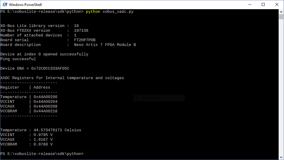
Congratulations! You have successfully read FPGA temperature and core voltages using XO-Bus Lite and Python. The Python library makes it very intuitive for people to experiment with the hardware using REPL Python shell. Keep exploring!