XO-Bus Lite Framework
The Numato Lab XO-Bus Lite is a framework for communicating with Numato Lab boards such as Saturn, Neso, Skoll, Styx etc from a host. XO-Bus Lite accelerates the development by providing an intuitive way of transferring data into and out of the FPGA. The XO-Bus Lite framework acts as a standard AXI4 Memory Mapped Master, and it can control AXI4 compliant slaves and use existing AXI4 infrastructure provided by Xilinx Vivado. This feature itself makes XO-Bus Lite Framework very powerful. Users can use most, if not all, IP cores that support AXI interface and read/write to memory and memory mapped registers on the devices directly from host PC. There is no need for any microprocessor (such as Microblaze), though XO-Bus Lite can also work alongside Microblaze or any other AXI Master. This gives users a high degree of flexibility in their designs. This article will help in getting started with the XO-Bus Lite Framework.
Prerequisites:
To work with XO-Bus Lite Framework, it is necessary to set up the development environment and manage prerequisites. This article uses the Numato Lab Neso Artix 7 FPGA Board as an example but the steps will be similar for other 7-Series boards (such as Skoll and Styx) as well. The Xilinx Spartan 6-series based boards such as Saturn will have a different XPS/EDK based workflow instead of Vivado based workflow, but the design process will be similar.
Hardware:
- Neso Artix 7 FPGA Module
- Xilinx Platform Cable II USB (not mandatory, but preferred for easier development)
Software:
- Xilinx Vivado 2016.1 or higher
- Microsoft Windows 10
Download and install Vivado Board Support Package files for Neso from here. Follow the README.md file on how to install Vivado Board Support Package files for Numato Lab boards. You may skip this step if you already installed the Vivado Board Support Package files for Numato Lab boards in the past while following other articles.
Request for the XO-Bus Lite Beta Release package from here. Extract the zip file to a convenient location. After extracting, there should a folder named xobuslite-release with following directory structure:
xobuslite-release (root directory of the package)
   |__demo   : This directory has demo applications utilizing XO-Bus Lite. Check out the README.md file inside that directory for more information.
   |__doc    : XO-Bus Lite documentation.
   |__driver : FTDI drivers and EEPROM configuration files.
   |__hdl    : XO-Bus Lite IP core packages for XPS and Vivado, Source files for ISE and example designs.
   |__sdk    : Host SDK for XO-Bus Lite for multiple languages is provided in this directory. Check out the README.md file inside the directory for more information.
Driver Installation
Numato Lab drivers for Neso (or Saturn, Skoll, Styx etc) need to be installed before it can be used with XO-Bus Lite framework. Browse to xobuslite-release\driver\ftdi directory and run setup.exe to install drivers for Numato Lab boards.
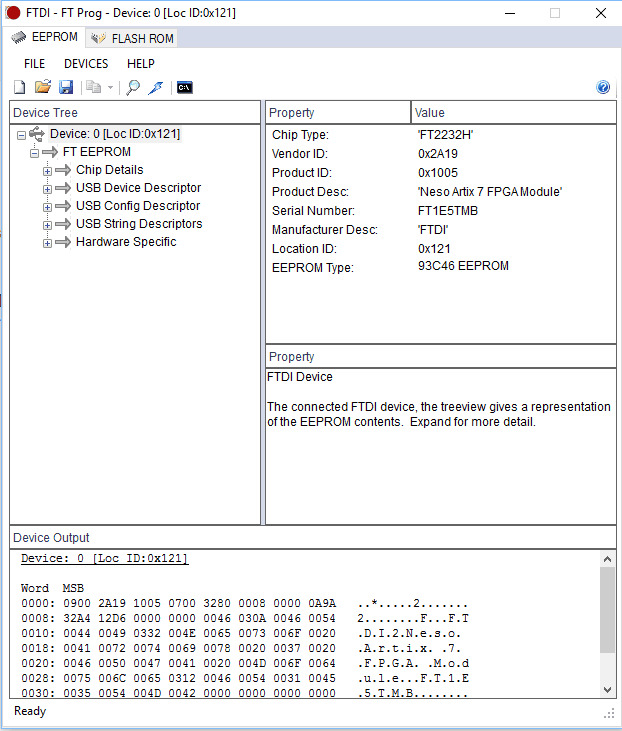
After driver installation is successful, download “FT Prog” program from the FTDI website. Connect Neso to the host PC using USB Micro-B cable and power it up. Click “Scan and Parse” icon (magnifier icon) on the toolbar. If Neso is detected similar to as shown below, then driver installation was successful.
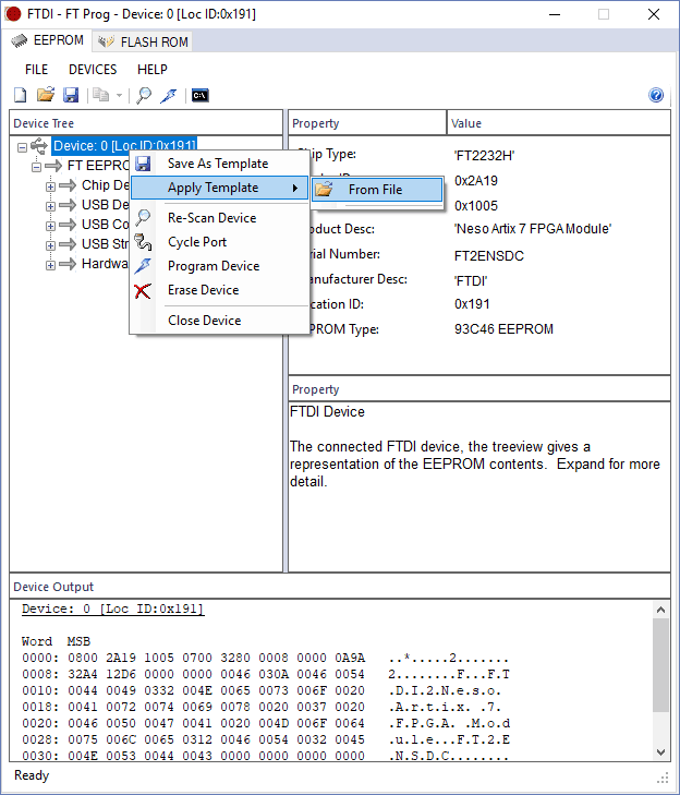
Right-click on “Device: 0” and select “Apply Template” -> “From File” as shown below
 Browse to the file
 Neso.xml inside xobuslite-release\driver\ftdi\eepconfig directory and click Open.
Click “Program Devices” icon (the thunderbolt icon next to magnifier icon) to program the template settings to Neso. Once the programming finishes, disconnect the Neso and reconnect it back again.
XO-Bus Lite SDK Setup
XO-Bus Lite host SDK needs to be set up before it can be for communication with XO-Bus Lite framework running on Neso. The XO-Bus Lite host API Library has bindings for C/C++, Java, Python and NodeJS. This article uses C++ library for demonstration, but feel free to explore the bindings for other supported languages. API is similar across languages. Follow the steps below to setup and build XO-Bus Lite host SDK for MinGW C++.
Step 1:
Download and install latest version of MinGW (It can be either 32 bit or 64 bit depending on your requirement) and add to PATH.
Step 2:
Run following commands in Command Prompt or PowerShell to make sure MinGW has been installed and configured correctly.
>> make -v
>> g++ --version
>> g++ -dumpmachine
If any of above commands return error, check the MinGW installation. Also check the machine architecture of g++. If you installed 64-bit MinGW, the output of g++ -dumpmachine should reflect that. Machine architecture must be known before running make since there is a separate makefile for each architecture.
Step 3:
Change to xobuslite-release -> sdk -> test folder inside the xobuslite-release folder and run make as shown below:
>> cd sdk
>> cd test
>> make -f Makefile.mingw32     // (for mingw 32-bit)
>> make -f Makefile.mingw64     // (for mingw 64-bit)
Step 4:
Connect Neso to host PC and run ..\bin\xobus-lite_test.exe executable. If everything went well, you would get output similar as below:
>> ..\bin\xobus-lite_test.exe
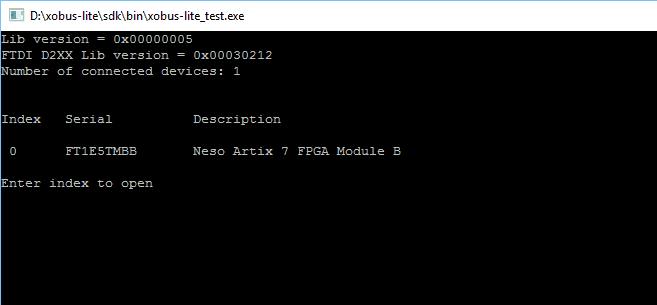
If the output is as shown in the image, close the window. Host-side XO-Bus Lite SDK for C++ has been set up successfully.
If everything went fine so far, proceed to the following section on Hardware design using XO-Bus Lite framework.
Hardware design using Vivado
Following steps will walk you through creating your first design utilizing XO-Bus Lite Framework using XilinxVivado Design Suite.
Step 1:
Start Vivado Design Suite, and select “Create New Project” from Quick Start section. The project wizard will open. Press “Next” to proceed with creating the project.

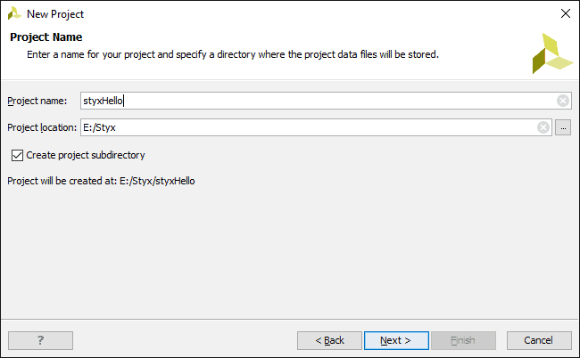
Step 2:
Enter a name and location for the project. This article uses the project name “xobus-lite-demo” but feel free to name it as per your preference. Select the checkbox “Create project subdirectory” as shown in image below and proceed with “Next” button.
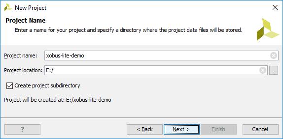
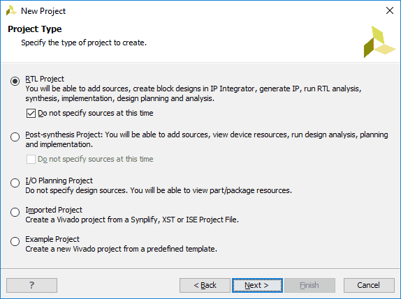
Step 3:
Select “RTL Project” as project type, and select the checkbox as shown below:
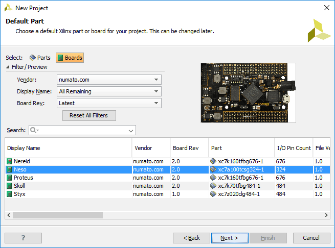
Step 4:
At the “Default Part” step, select “Boards” tab. Select “Neso” from the list and click Next. If Neso is not listed, make sure board support files are installed correctly.
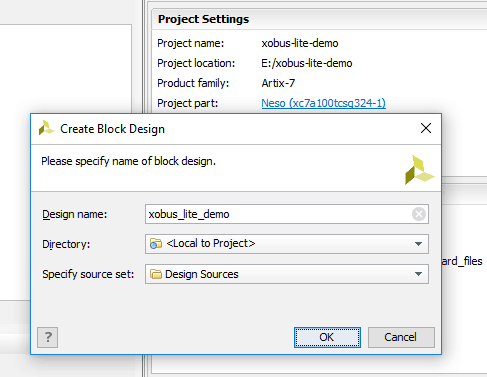
Step 5:
Under Flow Navigator, select “Create Block Design” in IP Integrator. Give an name to the block design. This article used “xobus_lite_demo” for the block design name.
Step 6:
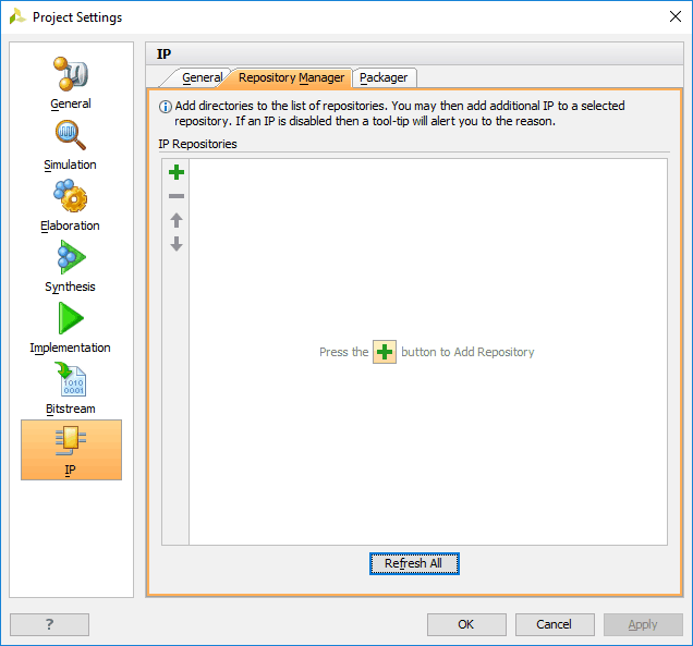
In the Flow Navigator section of the Vivado, click on “Project Settings” under “Project Manager”. In the Project Settings Window that comes up, click on “IP” section, go to “Repository Manager” tab under IP section, and click “+” to add location of custom IPs.
Step 7:
Browse to the directory where you had extracted the xobuslite-release package. Navigate to xobuslite-release\hdl\package\vivado and click “Select”. Vivado will scan the folder for any IP or Interface and list them out as shown in image below. There should be atleast 1 IP and 1 Interface detected by Vivado as shown in the image below. Click “OK” to confirm and “OK” once more to save the project settings.

Step 8:
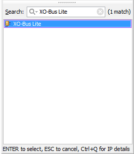
Go to Diagram window, right click and select “Add IP” from the popup menu. Search for XO-Bus Lite. Add it to the block design by double clicking.
Step 9:
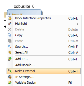
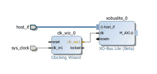
Right-click on the “host_if” port of XO-Bus Lite block and select “Make External”. This will make the “host_if” port as external port of the top-module. All communication between host PC and the FPGA happens via this port.
Step 10:
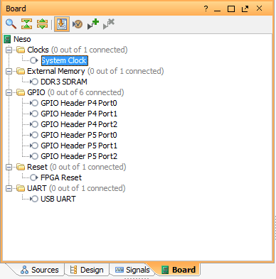
In the Block Design Window, select the “Board” tab on the bottom. The default peripherals available for the selected board (Neso in this case) will be displayed. Drag and drop “System Clock” into the diagram window. This will add a Clocking Wizard “clk_wiz_0” block in the design.
Step 11:
Connect “clk_out1” from Clocking Wizard to “clk” of XO-Bus Lite block.
Step 12:
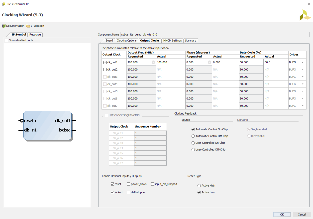
Double-click the “Clocking Wizard” block and change the reset type to “Active Low” as shown in picture. Click “OK” to save and close the customization window.
Step 13:
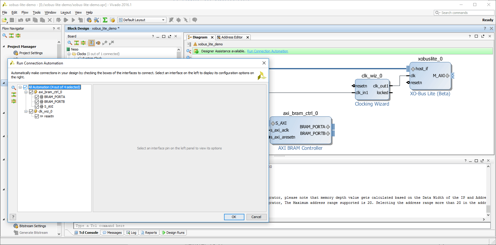
Add “AXI BRAM Controller” IP to the design. Click “Run Connection Automation” on the green bar on top of design area. Check “All Automation” and click “OK”.
Step 14:
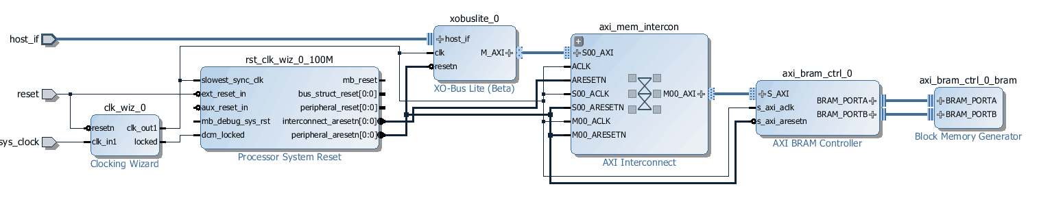
You will see a diagram similar as in the image below. You might need to click “Regenerate Layout” to tidy up the diagram and rearrange it in a better way. Now, Run Connection Automation once again.
Step 15:
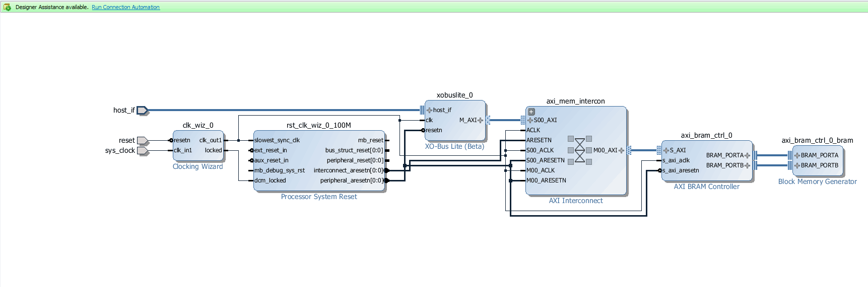
After running the last connection automation, a design similar to one shown below will be generated. As you might notice, “ext_reset_in” has now been connected to external “reset” signal. This is the final design which will be used by this article.
Step 16:
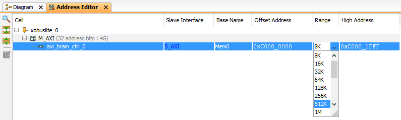
Go to Address Editor tab and change the size of BRAM to 512KB. Now, go back to Diagram tab and save everything.
Step 17:
Add constraints for the host interface port. For that, go to Project Manager. In the Sources window, right-click anywhere and select “Edit Constraints Sets”. Add a new constraints file named “xobus_lite_neso.xdc” and save below contents to that xdc file:
set_property -dict {IOSTANDARD LVCMOS33 PACKAGE_PIN J18} [get_ports {host_if_data[7]}]
set_property -dict {IOSTANDARD LVCMOS33 PACKAGE_PIN J17} [get_ports {host_if_data[6]}]
set_property -dict {IOSTANDARD LVCMOS33 PACKAGE_PIN G18} [get_ports {host_if_data[5]}]
set_property -dict {IOSTANDARD LVCMOS33 PACKAGE_PIN F18} [get_ports {host_if_data[4]}]
set_property -dict {IOSTANDARD LVCMOS33 PACKAGE_PIN E18} [get_ports {host_if_data[3]}]
set_property -dict {IOSTANDARD LVCMOS33 PACKAGE_PIN D18} [get_ports {host_if_data[2]}]
set_property -dict {IOSTANDARD LVCMOS33 PACKAGE_PIN B18} [get_ports {host_if_data[1]}]
set_property -dict {IOSTANDARD LVCMOS33 PACKAGE_PIN A18} [get_ports {host_if_data[0]}]
set_property -dict {IOSTANDARD LVCMOS33 PACKAGE_PIN K16} [get_ports host_if_txe_n]
set_property -dict {IOSTANDARD LVCMOS33 PACKAGE_PIN G13} [get_ports host_if_rxf_n]
set_property -dict {IOSTANDARD LVCMOS33 PACKAGE_PIN M13} [get_ports host_if_wr_n]
set_property -dict {IOSTANDARD LVCMOS33 PACKAGE_PIN D9 } [get_ports host_if_rd_n]
Step 18:
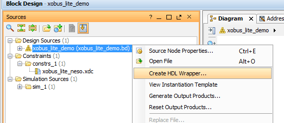
Right click on the design in the sources window and select “Create HDL Wrapper” from the popup menu. Click OK in the dialog window that appears, to finish generating the wrapper.
Step 19:
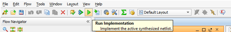
Click on the “Run Implementation” button (the green arrow) on the main toolbar. Vivado will now synthesize and implement the design. Status of implementation process will be shown in the log window.
Once the implementation is complete, click the “Generate Bitstream” button next to the implementation button to generate the bitstream for the design.
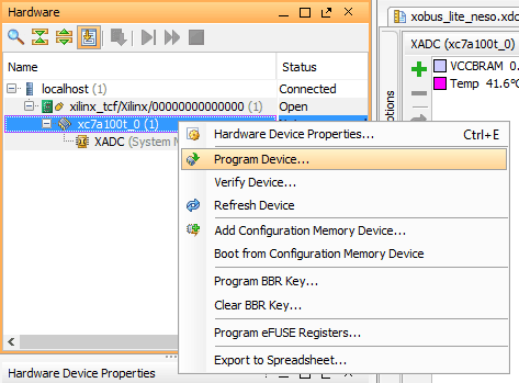
Step 20:
Program the generated bitstream to Neso. For that, make sure Xilinx Platform Cable is connected to Neso. Click “Open Target” under “Open Hardware Manager” in “Program and Debug” section of Flow Navigator. Right-click xc7a100t_0 and click “Program Device…” as shown in image below. Click “Program” and wait for programming to finish. It is also possible to program Neso without using Xilinx Platform Cable. Refer the “Configuring Neso Using Configuration Tool” section of Neso User Manual on how to do that.
Communication with Host
Step 1:
Change to the directory where the zip file was extracted. Further change to sdk directory.
Step 2:
If the compilation had succeeded during SDK setup, there would be an executable named xobus-lite_test.exe inside bin folder. Run the executable from the sdk folder:
>> bin\xobus-lite_test.exe
You should get output similar to the image shown below:
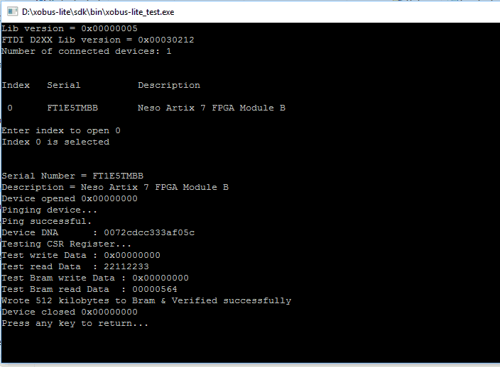
The code first pings the XO-Bus Lite framework for presence and response. If ping succeeds, code then reads the Device DNA of the FPGA on Neso. Once these steps are complete, it proceeds with writing 512KB of FPGA Block RAM with data, and then reads 512KB back from FPGA Block RAM to verify that contents match, which ideally should match if everything worked as expected.
Congratulations! You just communicated with FPGA using XO-Bus Lite framework! Refer the XO-Bus Lite User Manual inside xobuslite-release\doc and the source code of the test application to learn how to use XO-Bus Lite API.