Introduction
Numato Lab offers a range of GPIO modules designed to provide versatile, high-performance solutions for controlling and monitoring digital I/O. Available in various configurations, including different numbers of GPIOs and interface types like USB and Ethernet, these modules are ideal for applications in automation, testing, and device control. Each module is built to be easy to integrate, offering seamless communication and robust performance, ensuring reliability across a wide array of projects and industries. This documentation provides a comprehensive guide to getting started with the following modules:
- 8-Channel USB Pluggable GPIO Module – NL-USBG-C-008
- 16-Channel USB Pluggable GPIO Module – NL-USBG-C-016
- 32-Channel USB Pluggable GPIO Module – NL-USBG-C-032
- 64-Channel USB MOSFET Switch – NL-USBG-M-064
- 1-Channel USB Powered Relay(SPDT) Module
- 4-Channel USB Reed Relay Module – NL-USBR-H-004
- 32-Channel USB Relay(DPST) Module – NL-USBR-C-032
Prerequisites
To follow this article, you would need the following:
- Hardware:
- Numato Lab USB Pluggable GPIO (Numato IO™)
- USB B cable or USB Mini B cable according to the module (Refer user manual)
- Software:
- Numato Lab USB CDC Driver
- Tera Term
or - Any serial terminal emulator like PuTTY
Let’s get started
The following steps guide you through connecting the module to your PC and establishing communication with it.
Step 1:
Download and install Numato Lab USB CDC Driver from here. Follow the instructions in the provided documentation to complete the installation.
Step 2:
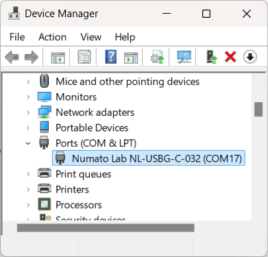
Connect the module to your PC using the USB cable. Open the Device Manager and note the assigned COM Port number.

Step 3:
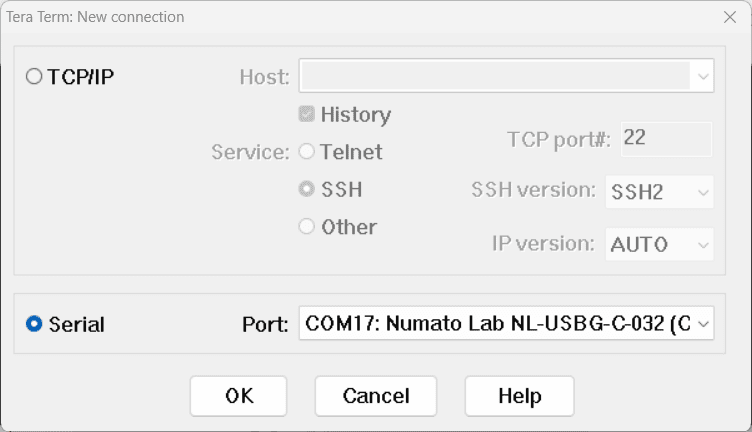
Launch Tera Term or any serial terminal emulator (such as PuTTY), and connect to the module using the noted COM Port.

Step 4:
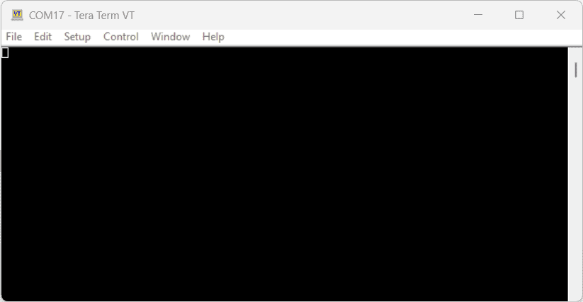
Once connected, you will be prompted with a screen to send commands and view the outputs.

Numato IO™ Generic Command Set
One of the key strengths of this module is its user-friendly command set, which streamlines interaction by abstracting the complexities of the USB protocol. This intuitive interface enables straightforward access to the module’s features. The following sections provide a detailed overview of the command set which is common for the Numato IO™ modules and guidance on its effective usage.
| No. | Command | Parameters | Usage | Description |
|---|---|---|---|---|
| 1 | gpio | set xxx | gpio set 000 | Control the GPIOs |
| clear xxx | gpio clear 000 | Control the GPIOs | ||
| read xxx | gpio read 000 | Read GPIO Input status | ||
| status xxx | gpio status 000 | Read GPIO status | ||
| readall | gpio readall | Read all GPIO status at a time | ||
| writeall xxxxxxxx | gpio writeall ffffffff | Control all GPIOs at a time | ||
| iomask xxxxxxxx | gpio iomask ffffffff | Control GPIOs mask status | ||
| iodir xxxxxxxx | gpio iodir 00000000 | Control GPIOs direction | ||
| notify on notify off | gpio notify on gpio notify off | Control Notify feature | ||
| notify get | gpio notify get | Read Notify Status | ||
| poweron xxxxxxxx xxxxxxxx | gpio poweron 00000000 ffffffff | Control GPIO Power-On IO direction & status respectively | ||
| 2 | adc | read xxx | adc read 000 | Read Analog to Digital Converter input value |
| 3 | relay | on xxx | relay on 000 | Control the relays |
| off xxx | relay off 000 | Control the relays | ||
| read xxx | relay read 000 | Read relay status | ||
| readall | relay readall | Read all relays status at a time | ||
| writeall xxxxxxxx | relay writeall ffffffff | Control all relays at a time | ||
| poweron xxxxxxxx | relay poweron ffffffff | Control relay poweron status at a time |
x in commands such as gpio writeall, gpio iomask, gpio iodir, and gpio poweron depends on the number of GPIO channels available on the module.Example:
- For an 8-channel module:
gpio writeall xx - For a 16-channel module:
gpio writeall xxxx - For a 32-channel module:
gpio writeall xxxxxxxx - For a 64-channel module:
gpio writeall xxxxxxxxxxxxxxxx
xxx in commands such as gpio set, gpio clear, gpio read, gpio status, adc read, relay on, relay off, and relay read represents the channel number. The range of these numbers depends on the number of GPIO or relay channels available on the module.For instance:
- On an 8-channel GPIO module, the range is
000 - 007. - On a 16-channel GPIO module, the range is
000 - 015. - On a 32-channel GPIO module, the range is
000 - 031.
relay commands are applicable only for the following modules :
- 1-Channel USB Powered Relay(SPDT) Module
- 4-Channel USB Reed Relay Module
- 32-Channel USB Relay(DPST) Module
The table below provides a detailed overview of the command patterns and their descriptions.
| No. | Command | Usage | Description |
|---|---|---|---|
| 1 | gpio | gpio set xxx | Sets GPIO ‘xxx’ output status to high. gpio set 000 – Sets IO0 to high state xxx can be 000 – 031 (according to the module) |
| gpio clear xxx | Sets GPIO ‘xxx’ output status to low. gpio clear 000 – Sets IO0 to low state xxx can be 000 – 031 (according to the module) |
||
| gpio read xxx | Read the input status present at ‘xxx’. gpio read 007 – Read input status of IO7 and print either ‘1’ or ‘0’ depending on the status xxx can be 000 – 031 (according to the module) |
||
| gpio status xxx | Read the GPIO status present at ‘xxx’ without changing the GPIO to inputs. gpio status 007 – Read status of IO7 and print either ‘1’ or ‘0’ depending on the status xxx = 000 to 031 (according to the module) |
||
| gpio iomask xxxxxxxx | Masks/Unmasks all GPIOs in a single operation. gpio iomask ffff0000 – Masks and/or unmasks GPIO at each bit position according to the bits of the specified hexadecimal value. 0 – To mask the GPIO & 1 – To unmask the GPIO. ‘ffff0000’ – 1111 1111 1111 1111 0000 0000 0000 0000: Masks GPIOs 0 – 15 & unmasks GPIOs 16 - 31. |
||
| gpio iodir xxxxxxxx | Sets direction of all GPIOs as Input/output mode in a single operation. gpio iodir 0000540f – Sets GPIOs as input/output at each bit position according to the bits of the specified hexadecimal value. 0 – To set the GPIO as output mode & 1 – To set the GPIO as input mode. ‘0000540f’ – 0000 0000 0000 0000 0101 0100 0000 1111: Sets GPIO 0,1,2,3,10,12 & 13 as input mode Sets GPIO 4,5,6,7,8,9,11,13,15,16-30 & 31 as output mode. |
||
| gpio readall | Read status of all GPIOs in single operation. gpio readall – Read all GPIO status and print xxxxxxxx. xxxxxxxx is a hexadecimal value, with binary 1 at positions for GPIOs in HIGH and 0 for GPIOs in LOW state. |
||
| gpio writeall xxxxxxxx | Control all GPIOs in single operation. Gpio writeall ffff67a4 – Sets and clears GPIO at each bit position according to the bits of the specified hexadecimal value. 0 – To clear the GPIO & 1 – To set the GPIO ‘ffff67a4’ – 1111 1111 1111 1111 0110 0111 1010 0100: Sets GPIO 2,5,7,8,9,10,13-14,16-30 & 31 Clears GPIO 0,1,4,6,11,12 & 15. Refer Understanding readall/writeall commands for GPIO Modules to know more. |
||
| gpio notify on | This command enables the gpio input change notification. When the gpio notify feature is enabled, changes to the input pins will be detected and a notification is sent to the host. To use notify feature on a GPIO, the GPIO must be set to input mode by using “gpio iodir” command. The GPIO change notification is sent to the host is in the below format. If GPIO change notification is “FFFFFFFE FFFFFFFF FFFFFFFF”, then 1. Current IODIR value is FFFFFFFF which means all GPIOs are set to input mode. 2. Previous GPIO values are FFFFFFFF. 3. Current GPIO values are FFFFFFFE. The GPIO 0 value is changed from logic 1 to 0. This change triggered the device to send this notification. |
||
| gpio notify off | This command disables the gpio input change notification feature. | ||
| gpio notify get | Returns whether Notify feature is enabled or disabled. | ||
| gpio poweron xxxxxxxx xxxxxxxx | This command is to control Power-On GPIO Direction and status in a single operation. gpio poweron ffff0000 000011c5 – Sets GPIOs IO direction and status respectively at each bit position according to the bits of the specified hexadecimal value. IO direction: 0 – To set the GPIO as output mode & 1 – To set the GPIO as input mode. IO status: 0 - To clear the GPIO & 1 - To set the GPIO. ‘ffff0000 000011c5’- (1111 1111 1111 1111 0000 0000 0000 0000) (0000 0000 0000 0000 0001 0001 1100 0101): GPIOs 0-15 are set to output mode & GPIOs 16-31 are set as input mode. GPIO 0,2,6,7,8 & 12 are set to High GPIO 1,3,4,5,9-11,13-14 & 15 are set to Low. |
||
| 2 | adc | adc read xxx | Reads the analog voltage present at the ADC input mentioned. “xxx” stands for the number of ADC input. The response will be a number that ranges from 0 – 1023. Please see examples below. adc read 000 – Reads analog input 0 adc read 004 – Reads analog input 4 xxx can be 000 to 006 (according to the module) |
| 3 | relay | relay on xxx | Turns a particular relay on. The parameter “x“ stands for the relay number. The relay number starts from zero. See some examples below. relay on 000 – Turns on relay 0 relay on 001 – Turns on relay 1 relay on 031 - Turns on relay 31 |
| relay off xxx | Turns a particular relay off. The parameter “x“ stands for the relay number. The relay number starts from zero. See some examples below. relay off 000 – Turns off relay 0 relay off 001 – Turns off relay 1 relay off 031 - Turns off relay 31 |
||
| relay read xxx | Returns the status of a particular relay. The parameter “x“ stands for the relay number. The relay number starts from zero. See some examples below. relay read 000 – Returns status of relay 0 relay read 031 – Returns status of relay 31 The data returned in response to this command will be either “on” or “off” depending on the current status of the relay. |
||
| relay readall | Reads the status of all relays in a single operation. The return value will be a hexadecimal number with binary value 1 at bit positions for relays in ON state and 0 for relays in OFF state. Eg: a return value 00000000 (binary 0000 0000 0000 0000 0000 0000 0000 0000) means all relays are OFF. A value FFFFFFFF (binary 1111 1111 1111 1111 1111 1111 1111 1111) means all relays are ON. relay readall – Returns status of all relays Refer Understanding readall/writeall commands for Relay Modules to know more. |
||
| relay writeall xxxxxxxx | Control all relays in a single operation. A hexadecimal value must be specified with desired bit positions set to 0 or 1. A value 0 at a bit position will turn off the corresponding relay. A value 1 at a bit position will turn on the corresponding relay. relay writeall ffffffff – Turns on all relays Refer Understanding readall/writeall commands for Relay Modules to know more. |
||
| relay poweron xxxxxxxx | This command is to control the relay status in a single operation. Eg. relay poweron ffff0000 Relays 0 - 15 are in off state and relays 16 -31 are in on state after the poweron. |
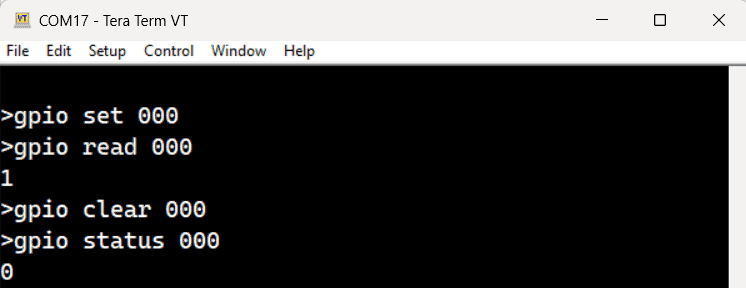
The image below is an example of how to send commands to the module using Tera Term. It shows the interaction process and the corresponding responses from the module.
