Introduction
Numato Lab’s GPIO modules implement an easy to use human readable set of commands. The greatest advantage of this command set is that the commands and the command behavior are same irrespective of the interface being used. So learning a single set of commands will help a user work with USB, Ethernet, WiFi or any interface for that matter. Of course, there are interface specific commands but all primary commands are exactly same. The primary command set can be divided in to two groups. The commands that works with individual GPIO, and the commands that can work with multiple GPIOs. The singular commands such as gpio set or gpio clear are very intuitive and fun to use but they tend to get inefficient as the number of GPIOs that needs to be managed goes up. For example, to turn ON 64 GPIOs using gpio set command, a user will end up having to send 64 individual commands. This certainly is difficult if the user is manually entering the commands, and neither is this very efficient for even a script or application. readall/writell commands can be a huge time saver in such situations. readall/writell commands can accept data for multiple GPIOs and apply them all in a single command execution cycle. These commands are considered to be advanced commands and are a bit complex to understand and use. This article attempts to break it down and make it easily understandable with the help of examples.
Implementation of readall/writeall commands for relays is much easier to understand. So we recommend reading and understanding the article “Understanding readall/writeall commands for Relay Modules” even if you are only concerned with GPIOs. Once these commands are understood as they apply to relays, it will be much easier to understand how they work with GPIOs. On GPIO modules the readall/writeall commands are implemented as sub-commands to the gpio command. So these commands are always invoked as part of gpio command.
Applicable Products*
* Some exclusions may apply. Please see the product specification/user manual for commands and features supported by individual products.
Prerequisites
Some introductory knowledge on how GPIO modules work and how to send commands to the modules can be very helpful. Basic knowledge on number systems (primarily Hexadecimal and Binary) and conversion between them is strongly recommended.
Available readall/writeall related commands
There are four commands available on GPIO devices that are related to and including readall/writeall. They are
- iomask – Mask and unmask IOs to work with selected IOs.
- iodir – Sets direction of IOs
- readall – Reads IO status
- writeall – Writes IO status
The following sections will discuss their usage in detail.
Using iomask command with GPIO Modules
readall, writeall and iodir commands are designed to work with all IOs on a GPIO module at once. Of these commands, readall command simply reads the GPIO status and it does not affect the state of the IO in any way. But writeall and iodir are can change the state of the IOs when executed. As we know, these commands are designed to affect all IOs at once. But what if one wants these commands to affect only a subset of all the IOs available. For example, how to change the status/direction of four GPIOs on a 32 Channel GPIO Module without affecting the rest 28 GPIOs? iomask command is the answer. iomask command offers a convenient way to select or deselect any subset of IOs to precisely control which IOs are affected by writeall/iodir commands . The selected/deselected IOs doesn’t have to be contiguous or in any particular order.
iomask command is a sub-command to the gpio command and is issued to the device as below.
The mask argument is a hexadecimal number representing the IO mask to be applied to the device. The length of the argument will vary depending on the number of GPIOs on the device. The mask data is a bit field where each bit represents a single GPIO. Since each hexadecimal character can hold four bits of data, the length of the argument will be Number Of GPIOs/4. For example, a 32 Channel USB GPIO Module has 32 GPIOs and thus the length of the iomask argument would be 32/4 = 8. When a bit corresponding to the GPIO is set to 1, that GPIO is selected and is affected by writeall and iodir commands. When a bit corresponding to the GPIO is set to 0, that GPIO is deselected and is not affected by writeall and iodir commands.
Let’s take a look at an example. Assume we need to select GPIO0, GPIO6 and GPIO7 on a 32 Channel USB GPIO Module. Let’s write down the corresponding mask value in binary and convert to hexadecimal. The first column of the table below shows the mask in binary format. Note the bits 0, 6 and 7 where the value is 1 and the rest of the bits are zeros. This means the GPIOs 0, 6 and 7 will be affected by subsequent writeall and iodir commands and the rest of the IOs will not be affected at all.
| Binary (31 – 0) | Hex |
| 0000 0000 0000 0000 0000 0000 1100 0001 | 000000C1 |
When the binary data above converted to hexadecimal notation, we get the value 000000C1. Please note that the argument must contain the exact number of characters, 8 in this example. So make sure to preserve all preceding zeros. So finally the iomask can be issued to the device as shown below.
iomask command can be issued any number of times to select and deselect IOs to work with even complex IO patterns very easily and effectively. All IOs are deselected at power up so sending iomask at least one time is necessary before writeall/iodir commands can be used. readall command does not require any specific iomask to be set for operation.
Using iodir command with GPIO Modules
All GPIOs available on GPIO devices do have specific directions associated with them. This fact is not very important when using singular IO commands such as gpio get and gpio set. This is because the device will select appropriate direction settings for each GPIO as the command is executed. For example, the GPIO will be configured as OUTPUT when gpio set/clear command is executed and configured as INPUT when gpio read command is executed. But when using readall/writeall commands, the device will not configure the GPIO direction automatically. So it is important to configure the IO direction appropriately before issuing readall/writeall commands.
Before issuing the iodir command, make sure to send an iomask command to select the IOs appropriately.
iodir command is a sub-command to the gpio command and is issued to the device as below.
The IO Direction Data argument is a hexadecimal number representing the IO directions to be applied to the device. The length of the argument will vary depending on the number of GPIOs on the device. The direction data is a bit field where each bit represents a single GPIO. Since each hexadecimal character can hold four bits of data, the length of the argument will be Number Of GPIOs/4. For example, a 32 Channel USB GPIO Module has 32 GPIOs and thus the length of the iodir argument would be 32/4 = 8. When a bit corresponding to the GPIO is set to 1, that GPIO is configured as INPUT. When a bit corresponding to the GPIO is set to 0, that GPIO is configured as OUTPUT.
Let’s take a look at an example. Assume we need to configure GPIO0, GPIO6 and GPIO7 on a 32 Channel USB GPIO Module as inputs and configure the rest of the GPIOs as outputs. Let’s write down the corresponding mask value in binary and convert to hexadecimal. The first column of the table below shows the IO direction data in binary format. Note the bits 0, 6 and 7 where the value is 1 and the rest of the bits are zeros. This means the GPIOs 0, 6 and 7 will be configured as inputs and the rest would be configured as outputs.
| Binary (31 – 0) | Hex |
| 0000 0000 0000 0000 0000 0000 1100 0001 | 000000C1 |
When the binary data above converted to hexadecimal notation, we get the value 000000C1. Please note that the argument must contain the exact number of characters, 8 in this example. So make sure to preserve all preceding zeros. So finally the iodir command can be issued to the device as shown below.
Using readall Command with GPIO Modules
The readall command is used to read the status of all GPIOs present on the device in a single command cycle. readall command for GPIOs is executed by sending the command gpio readall . Please note that the readall command does not require any arguments. The device responds to the readall command by sending back a hexadecimal number . The length of the returned number will vary depending on the number of GPIOs on the device. For example, a 8 Channel USB GPIO Module will respond to readall command with one byte worth of information, ie; two characters. This is because each bit in the returned number represent the state of one GPIO. So each character in the response can represent the state of up to four GPIOs. Lets take a look at a real world example. The picture below shows gpio readall command executed on a 32 Channel USB GPIO Module.
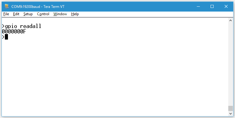
As we can see, the response has eight characters. Considering each character represents the state of four GPIOs, we can see that the whole response can represent the states of 8 x 4 = 32 GPIOs, which is what we would expect from a 32 Channel USB GPIO Module. Now the last part of understanding the readall command is to learn how to decode the state of individual GPIOs from the response. This is accomplished by simply converting the response from the device to binary format (remember, the response will be in Hexadecimal format). The conversion can be done manually by using a scientific calculator or if you are writing a program or script you may use conversion functions provided by the specific programming language. For example, when converting the response from the 32 Channel USB GPIO Module in the picture above, we will get the result as shown below.
| Hex | Binary (31 – 0) |
| 0000000F | 0000 0000 0000 0000 0000 0000 0000 1111 |
We can see that the higher 24 positions in the binary data are zeros and the lowest four positions are ones. This means that the GPIO 0 – 3 are in ON state and GPIOs 4 – 31 are in OFF state. In essence, a 1 at any position indicate the GPIO at that position is in ON state and 0 at any position indicates that the GPIO at that position is in OFF state. Please note that the readall command does not return what was previously written using writeall command, rather it returns the digital state corresponding to the voltages applied to the GPIOs externally.
Using writeall Command With GPIO Modules
Just like readall command provides a method to read the status of all GPIOs at the same time, writeall command provides a mechanism to change the state of all GPIOs through a single command. The concept of using writeall command is very similar to readall except that instead of receiving data from the device, writeall command will send data to the device so the GPIO status can be changed. writeall command for GPIOs is executed by sending command gpio writeall <data> where the data represents the GPIO output state data to be sent to the device. The GPIO state data is always represented in hexadecimal notation. The length of the data will depend on the number of GPIOs on the device, generally one character per four GPIOs present on the device.
Let’s take a look at a practical scenario. Suppose we want to turn ON the four GPIOs at the highest positions on a 32 Channel USB GPIO Module. The GPIO state data for this would look like below in binary format.
| Binary (31 – 0) |
| 1111 0000 0000 0000 0000 0000 0000 0000 |
As we learned with readall command, a 1 at any bit position will turn ON a GPIO at that position and 0 at any bit position will turn OFF the GPIO at that position. When this binary data is converted to hexadecimal the result would be f0000000 and this is the value we will be sending to the device as the argument to writeall command. So the complete command to be sent to the device to turn ON the upper four GPIOs would be as follows.
Conclusion
readall and writeall commands offer very powerful and flexible mechanism to work with large number of GPIOs. While these commands may be slightly more difficult to understand and implement, they will help save a lot of time and effort eventually.
What is the max speed for readall and writeall for “USB GPIO Modules” and “Ethernet GPIOModules”?
May 23, 2018 at 12:00 pmIf 16 channels configure as input and 16 channels configure as output, dose readall and writeall work?
I need to generate a 140 HZ clock on 16 outputs and read back data from 16 inputs channels.