Introduction
Node.js is becoming a de facto platform for rapidly building web-based and other applications, thanks to Javascript that has been a favorite language for a huge number of developers. Node.js allows programmers with Javascript knowledge to write applications effortlessly. Also, Javascript’s asynchronous nature is very helpful to implement solutions easily that are usually relatively difficult with other languages. Node.js certainly is capable of replacing popular scripting languages such as Perl or Python to create scripts and applications for automation and other purposes. A huge collection of packages at https://www.npmjs.com/ makes it easy to find a lot of functionality and add to your application with a minimum amount of code. And by the way, Node.js works on multiple operating systems including Windows, Linux, and Mac too.
USB GPIO modules (and other GPIO modules as well) are primarily used for some sort of automation such as Industrial Automation and Factory Automation. While USB GPIO modules do provide a mechanism to turn on/off GPIOs and read external voltages, the hardware modules themselves are far from a complete turnkey solution. In most scenarios, to implement a complete solution, the hardware needs to be complemented with a piece of software that can accept inputs from the real world through the GPIO module, process them using various algorithms and send signals out through the USB GPIO hardware. This article discusses various aspects of using Node.js for writing scripts/applications to control Numato Lab’s USB GPIO modules so that the reader will become familiar with the basic concepts with the help of examples.
Applicable products
Prerequisites
The reader is expected to be familiar with Node.js and commands supported by the device. More information about the supported commands is available in the product user manual.
Node.JS, NPM and the SerialPort module for Node must be installed on the target machine. More information on how to install these applications can be found on the links below.
Fundamentals of communicating with Numato Lab USB GPIO
Just like most other USB based products form Numato Lab, the USB GPIO devices present themselves as a simple Serial Port to the host machine. This serial interface allows the device to be programmatically controlled by using APIs provided by the Operating System. Be it Windows, Linux, Mac, Android or any other operating system, the behavior is the same. The only requirement is that the host operating system supports USB CDC devices, which almost all popular operating systems do.
Node.js does not have support for Serial Ports built into the platform. But there are a few NPM packages that provide easy to use APIs to access Serial Ports from within Node.js. The exact APIs and features offered by these packages vary but it should be possible to use most of these packages to work with Serial Port and thus with Numato Lab USB GPIO devices as well. This article uses the ‘serialport‘ package which is one of the popular packages and it offers some intuitive and easy to use APIs.
Interacting with USB GPIO device programmatically can be broken down into the following steps.
- Open the port corresponding to the device
- Send commands to the device. The commands are ASCII human-readable strings.
- Read back the response from the device where applicable. The responses from the device also human-readable ASCII strings.
- Close the port when the operation is complete
The following sections will discuss in detail about each of these steps.
Opening the port
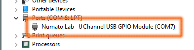 Before the port can be opened, the port name for the corresponding device must be located. On Windows, this can be usually done by visiting the Device manager and looking up the port name manually. Here is the example image on the right, the port name for the GPIO module would be COM7. On Linux and Mac OSX, the attached devices should be visible in the /dev directory.
On most Linux distributions, the device will have a name in the form ttyACMx where x will be a number. Running the command ls /dev/ttyACM* should list all attached CDC devices. On MAC OSX, the device should be visible under /dev directory but with a different name. Running ls /dev command print all devices and it should be relatively easy to find the name representing the USB GPIO device. The images below show Linux and Mac OSX examples.
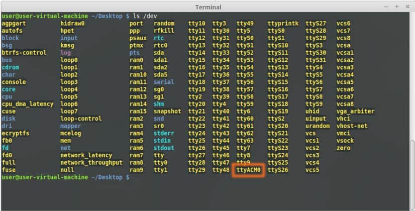
Device listing on Linux
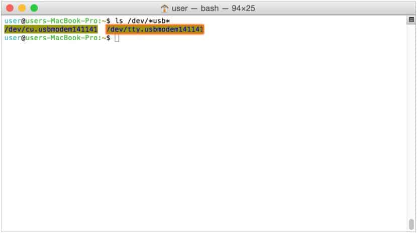
Device listing on Mac OSX
If there are other CDC devices connected to the host, they will also have very similar names.
Once the port name is figured out, opening the port is very easy. Before opening the port, the serialport package must be imported and a new object representing the port should be created. The following code both these steps. Also, this code snippet uses the baud rate 19200. The speed of communication does not depend on the baud rate used so any legal baud rate value can be used here.
var SerialPort = require("serialport").SerialPort
//On Windows use the port name such as COM4 and on Linux/Mac, use the device node name such as /dev/ttyACM0
var port = "com4";

var portObj = new SerialPort(port,{
 baudrate: 19200
}, false);
The object created above can be used to open the port and communicate with the device. The objects Open() method opens the port for communication. See the code snippet below.
portObj.open(function (error){
  if ( error ) {
		console.log('Failed to open port: ' + error);
  } else {
   //Communicate with the device
}
Sending commands to the device
Once the port corresponding to the device is opened successfully, commands can be set to the device using the write() method provided by the serialport package. The write() method accepts a string contains the command and is sent to the device. Since the device expects the command to end with a Carriage Return (hex value 0x0A), it is important to add a \r at the end of all commands. The write() method also accepts a callback which can be used to process the success/failure returned by the method. Make sure open() method is called on the port object and the port is open before calling write() method.
portObj.write("ver\r", function(err, results){
    if(error){
        console.log('Failed to write to port: '+ error);
    }
});
Depending on the exact command sent, the device may or may not respond with some data. This data can be captured by reading the port immediately after sending the command. The next section discusses this in details.
Reading a response from the device
The serialport package provides an event called data event to receive data over the serial port. This event is triggered when the device sends data back in response to a command. Accepting data from a connected device is as easy as defining a callback for the data event. The code snippet below defines a callback function for the data event and within the callback, the returned data is printed.
portObj.on('data', function(data){
	console.log('Data Returned by the device');
	console.log('--------------------');
        console.log(String(data));
	console.log('--------------------');
});
The response from the device contains the original command, the actual result of the command and a command prompt character with a couple of newlines. This data can be further processed to extract the specific result data using string manipulation functions or regular expression. This can be explained with the help of the following image.
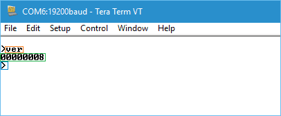
The characters marked with Orange rectangle is the original command sent. Since the device echoes all characters received, the command will be present in the data that is read from the device. The characters that are marked with the Green rectangle is the actual result of the command. Finally, the Greater Than (>) character marked in Blue rectangle is the command prompt. There is also a newline character after each line. It is easy to see that of all the data received, only the characters marked in the Green rectangle is the actual result of interest. It is easy to extract the result from the received data by using a regular expression of string functions. The sections below will briefly discuss how to extract the result for each command.
USB GPIO Commands
The table below lists the most common commands supported by Numato Lab’s USB GPIO devices along with a description and examples. All commands are human readable ASCII strings. The following sections talks in a bit more detail about using these commands.
| No. | Command | Example | Description |
|---|---|---|---|
| 1 | ver | ver | Returns current firmware version. |
| 2 | id | id get | Id get reads the module ID. |
| id set xxxxxxxx | Id set will assign a new ID to the module. “x” stands for alphanumeric characters including symbols. The new ID must be exactly 8 characters in length. | ||
| 3 | gpio | gpio set x | Sets the GPIO output status to high. Here “x” is the number of the GPIO. This command accepts GPIO number from 0 -7, total 8 values Please see examples below. gpio set 0 – Sets GPIO 0 to high state gpio set 4 – Sets GPIO 4 to high state |
| gpio clear x | Sets the GPIO output status to low. Here “x” is the number of the GPIO. This command accepts GPIO number from 0 -7, total 8 values. Please see examples below. gpio clear 0 – Sets GPIO 0 to low state gpio clear 4 – Sets GPIO 4to low state |
||
| gpio read x | Reads the digital input status present at the input mentioned. Here “x” stands for the number of GPIO. This command accepts GPIO number from 0 -7, total 8 values. The response will be either “on” or “off” depending on the current digital state of the GPIO. Please see examples below. gpio read 0 – Reads GPIO 0 status gpio read 4 – Reads GPIO 4 status |
||
| gpio iomask xx | Set mask for selectively update multiple GPIOs with writeall/iodir command. A hexadecimal value(xx) must be specified with desired bit positions set to 0 or 1 with no “0x” prepended (eg 02, ff). A 0 in a bit position mask the corresponding GPIO and any update to that GPIO is ignored during writeall/iodir command. A 1 in a bit position will unmask that particular GPIO and any updates using writeall/iodir command will be applied to that GPIO. This mask does not affect the operation of set and clear commands. gpio iomask ff – Unmask all GPIOs. gpio iomask 00 – mask all GPIOs. Refer Understanding readall/writeall commands for GPIO Modules to know more. |
||
| gpio iodir xx | Sets the direction of all GPIO in a single operation. A hexadecimal value(xx) must be specified with desired bit positions set to 0 or 1 with no “0x” prepended (eg 02, ff). A 0 in a bit position configures that GPIO as output and 1 configures as input. Before using gpio readall/writeall commands, the direction of GPIO must be set using “gpio iodir xx” command. GPIO direction set by using iodir command will be modified with subsequent set/clear/read commands (only affects the GPIO accessed using these commands). gpio iodir 00 – Sets all GPIO to output. Refer Understanding readall/writeall commands for GPIO Modules to know more. |
||
| gpio readall | Reads the status of all GPIO in a single operation. The return value will a hexadecimal number with binary value 1 at bit positions for GPIO in HIGH state and 0 for GPIO in LOW state. Eg: a return value 00 (binary 0000 0000) means all GPIO are OFF. A value FF (binary 1111 1111) means all GPIO are ON. gpio readall – Reads all GPIO status. Refer Understanding readall/writeall commands for GPIO Modules to know more. |
||
| gpio writeall xx | Control all GPIO in a single operation. A hexadecimal value (xx) must be specified with desired bit positions set to 0 or 1. A value 0 at a bit position will clear the corresponding GPIO. A value 1 at a bit position will set the corresponding GPIO. gpio writeall ff – Sets all GPIO to high state. Refer Understanding readall/writeall commands for GPIO Modules to know more. |
||
| gpio poweron xx xx (feature available from firmware version A0M10.01 onwards) | Sets the GPIO status on power-on according to the hexadecimal value and IO direction mentioned. xx – GPIO direction [0 – output, 1 – input] XX –poweron value [0 – Clear GPIO, 1- Set GPIO] gpio poweron 0f 5d ‘0f’ ‘5d’ – 0000 1111 0101 1101 GPIOs 0 to 3 – input GPIOs 4 to 7 – output Set GPIOs 0,2,3,4&6, Clear GPIOs 1,5&7 |
||
| 4 | adc | adc read x | Reads the analog voltage present at the ADC input mentioned. “x” stands for the number of ADC input. The response will be a number that ranges from 0 – 1023. Please see examples below. adc read 0 – Reads analog input 0 adc read 4 – Reads analog input 4 |
| 5 | info | info (feature available from firmware version A0M10.01 onwards) | Displays the information on GPIO power-on status |
Retrieving device firmware version
The device firmware version can be retrieved by sending the command ver. This command does not have any arguments. Sending this command to the device with a trailing carriage return will cause the device to respond with the firmware version. The following code snippet will send the version command to the device which is already open.
portObj.write("ver\r", function(err, results){
    if(error){
        console.log('Failed to write to port: '+ error);
    }
});
The received data in response to ver command can be extracted by using the following code snippet. The first line splits the received data into multiple strings with newline as a delimiter. Index 1 of the resulting array will have the result we are looking for. Index 0 will contain the original command sent as well. Other members of the array can be ignored.
rawOutput = String(data).split('\n');
if (rawOutput[0].indexOf('ver') != -1) {
    print.green('\nFirmware version - ' + rawOutput[1].substr(1));
}
Setting and retrieving device ID
Most Numato Lab’s USB GPIO devices support a user-modifiable ID. This ID can be set to any alphanumeric string (length of the string must be exactly eight characters) by using the id set command and it can be later retrieved by using the id get command. This ID can be used as a unique device identifier, batch/series identifier, etc… The ID written to the device is stored in non-volatile memory and is persistent over power cycles.
The ID can be written to the device using the piece of code below.
var id = "12345678"; //Must be 8 characters in length
portObj.write("id set " + id + "\r", function(err, results){
    if(error){
        console.log('Failed to write to port: '+ error);
    }
});
The current ID of the device can be requested by sending the id get command. The device will respond with the current ID when this command is received. The code snippet below shows how to send id get command to a device.
portObj.write("id get\r", function(err, results){
    if(error){
        console.log('Failed to write to port: '+ error);
    }
});
The received data in response to id get command can be extracted by using the following code snippet. The first line splits the received data into multiple strings with newline as a delimiter. Index 1 of the resulting array will have the result we are looking for. Index 0 will contain the original command sent as well. Other members of the array can be ignored. The code snippet below shows how to extract and print the ID sent by the device.
rawOutput = String(data).split('\n');
if (rawOutput[0].indexOf('id get') != -1) {
   print.green('\nModule ID - ' + rawOutput[1].substr(1));
}
Using GPIOs as a digital output
Digital Output mode is one of the three modes supported by Numato Lab’s GPIO devices where the GPIO can generate a digital output logic state 1 or 0 based on the command sent for the host. There is no special command to set the GPIO to a specific mode, rather the mode/direction is selected automatically by the firmware when an IO command is received. Two commands are available to manipulate individual GPIOs in output mode. They are gpio set and gpio clear. As the command names suggest, the commands turn ON or turn OFF a GPIO respectively.
The code snippet below shows how to set gpio set command to a device to turn ON GPIO0 (GPIO at index 0).
var gpioIndex = 0;
portObj.write("gpio set " + gpioIndex + "\r", function(err, results){
    if(error){
        console.log('Failed to write to port: '+ error);
    }
});
The code snippet below shows how to set gpio celar command to a device to turn OFF GPIO0 (GPIO at index 0).
var gpioIndex = 0;
portObj.write("gpio clear " + gpioIndex + "\r", function(err, results){
    if(error){
        console.log('Failed to write to port: '+ error);
    }
});
Using gpio set and gpio clear command are very easy to use when there are only a few IOs that needs to be controlled. But with a larger device that has 16, 32 or larger number of GPIOs, sending one command per GPIO can become a bit tedious when a bunch of GPIOs needs to change at the same time. To help with such scenarios, some of the GPIO devices support writeall/iodir/iomask sub-commands/arguments. Using these commands, multiple IOs can be controlled with one command instead of sending a large number of commands.
All Numato Lab’s GPIO devices do support writeall/readall/iomask/iodir commands. But the GPIOs available on relay devices may not support these commands.
Using GPIOs as a digital input
Digital input mode allows the external digital signal state to be read using GPIOs over USB. Using a GPIO as digital input is very easy. Simply executing the command gpio read will return the digital state applied at the GPIO externally. This command accepts one argument which is the GPIO index. For example, gpio read 2 will cause the device to respond with the state at GPIO2. The response from the device will be either 1 or 0 depending on the digital signal applied.
var gpioIndex = 0;
portObj.write("gpio read " + gpioIndex + "\r", function(err, results){
    if(error){
        console.log('Failed to write to port: '+ error);
    }
});
The received data in response to gpio read command can be extracted by using the following code snippet. The first line splits the received data into multiple strings with newline as a delimiter. Index 1 of the resulting array will have the result we are looking for. Index 0 will contain the original command sent as well. Other members of the array can be ignored. The code snippet below shows how to extract and print the ID sent by the device.
rawOutput = String(data).split('\n');
if (rawOutput[0].indexOf('gpio read') != -1) {
   print.green('\nGPIO input state - ' + rawOutput[1].substr(1));
}
Using GPIOs as analog input
Analog input mode allows external signal value to be read over USB. Compared to Digital Input mode where the ON or OFF state is returned, Analog input mode allows reading any value between 0V and VDD. Simply executing the command adc read will return a count between 0 and 1023 depending on the voltage of the analog signal applied externally. This command accepts one argument which is the Analog Input index. For example adc read 2 will cause the device to respond with the state at Analog Input 2. The response from the device can be any value for 0 to 1024 depending on the signal applied. The code snippet below shows how to send adc read command to the device.
var gpioIndex = 0;
portObj.write("adc read " + gpioIndex + "\r", function(err, results){
    if(error){
        console.log('Failed to write to port: '+ error);
    }
});
The received data in response to adc read command can be extracted by using the following code snippet. The first line splits the received data into multiple strings with newline as a delimiter. Index 1 of the resulting array will have the result we are looking for. Index 0 will contain the original command sent as well. Other members of the array can be ignored. The code snippet below shows how to extract and print the ID sent by the device.
rawOutput = String(data).split('\n');
if (rawOutput[0].indexOf('adc read') != -1) {
   print.green('\nAnalog count - ' + rawOutput[1].substr(1));
}
Working with multiple GPIOs
All Numato Lab’s USB GPIO devices support special commands to control multiple GPIOs at once. These commands will help minimize the amount of code required and the traffic on the USB interface. The following commands are available for this purpose.
- gpio iomask – Sets mask to allow/disallow GPIO manipulation by the commands below
- gpio iodir – Sets the direction of GPIOs
- gpio readall – Reads the GPIOs
- gpio writeall – Writes new values to the GPIOs
As the names suggest, readall and writeall commands are used to read the states of multiple GPIOs and write new values to the GPIOs respectively. Unlike the gpio read/set/clear commands, IO mask and IO direction must appropriately be configured before using readall/writeall commands. The iomask command is used to manipulate a mask maintained by the firmware internally. When readall, writeall or iodir commands are executed, the device will first check the mask. If the mask corresponding to a particular GPIO is 0, then that GPIO is ignored and is not affected by readall, writeall or iodir commands. If the mask corresponding to a GPIO is 1, readall, writeall or iodir commands will affect that particular GPIO. For example, if the mask is set to 0x00 by sending the command gpio iodir 00, then the mask bit for all eight GPIOs (Assuming 8 channel GPIO module) will be zero and readall, writeall or iodir commands will not have any effect on any GPIOs whatsoever. On the other hand, if the mask is set to 0xFF by sending the command gpio iodir FF, then the mask bit for all eight GPIOs (Assuming 8 channel GPIO module) will be 1 and all GPIOs can be affected by readall, writeall or iodir commands. Any value between 0x00 and 0xFF can be used as a mask to select any combination of GPIOs for operation.
The iodir command sets the direction of GPIOs. gpio read/set/clear commands will set the direction of the target GPIO automatically when executed. But readall, writeall commands will need the GPIO direction to be set appropriately prior to their execution. The direction is set by simply sending the command with the appropriate argument. Each bit in the argument represents the direction of one GPIO. A value of 1 will set the corresponding GPIO to input mode and a value of 0 will set the GPIO to output mode. For example, the command gpio iodir 00 will put all GPIOs into output mode and gpio iodir FF will put all GPIOs to input mode.
Once the direction is set, multiple GPIOs can be written to or read from using readall or writeall commands.
Closing the port
It is recommended to close the port once all operations on the port device are complete. In this case, a previously opened port can be closed by calling the close() method. The code below shows how to close a port. It is not necessary to close the port after each operation, rather close the port only after all operations are complete.
portObj.close();
A complete program
The following code puts together the techniques we saw in the above sections into a single standalone program. This code sends a few commands to the device and prints the data returned by the device. Any other command described in the product user manual can be sent to the device the same way.
var SerialPort = require("serialport").SerialPort
var port = "COM11";

var portObj = new SerialPort(port,{
  baudrate: 19200
}, false);

portObj.on('data', function(data){
	console.log('Data Returned by the device');
	console.log('--------------------');
        console.log(String(data));
	console.log('--------------------');
        portObj.close();
});

portObj.open(function (error){
  if ( error ) {
		console.log('Failed to open port: ' + error);
  } else {

               console.log('Writing version command to port');
		portObj.write("ver\r", function(err, results){
			if(error){
				console.log('Failed to write to port: '+ error);
			}
		});

		console.log('Writing command gpio set 0 to port');
		portObj.write("gpio set 0\r", function(err, results){
			if(error){
				console.log('Failed to write to port: '+ error);
			}
		});

		console.log('Waiting for two seconds');
		setTimeout(
			function(){
				console.log('Writing command gpio clear 0 to port');
				portObj.write("gpio clear 0\r", function(err, results){
					if(error){
						console.log('Failed to write to port: '+ error);
					}
				});

				setTimeout( function(){process.exit(code=0);}, 1000);
			}
		,2000);
  }
});