Introduction:
VGA (Video Graphics Array) is an analog interface used to display visual data on computer monitors. Till few years back, it was the most used display interface. It is now being slowly replaced by HDMI. The data can be displayed on monitors via VGA by using VGA Expansion Module and Saturn IO Breakout module with Telesto MAX 10 FPGA Module. In this tutorial, a simple project is implemented to display colours using VGA. Let’s get started!
Prerequisites:
Hardware:
- Telesto MAX 10 FPGA Module
- Saturn IO Breakout Module
- VGA Expansion Module
- Intel USB Blaster II JTAG (optional)
- Monitor with VGA input and VGA cable
Software:
- Quartus Prime (Version 2017.1 or later)
Step 1:
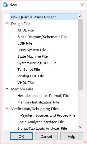
Open Quartus -> File -> New, select New Quartus Prime Project and click OK.
Step 2:
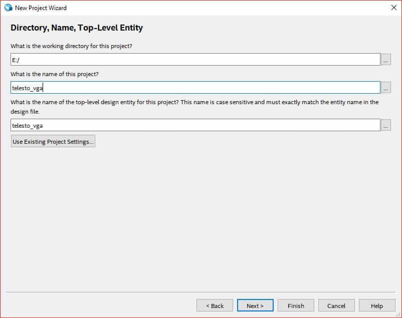
The “New Project Wizard” will open. Click Next. In ‘Directory, Name and Top-Level Entity’, select directory of your choice and provide a project name.
Step 3:
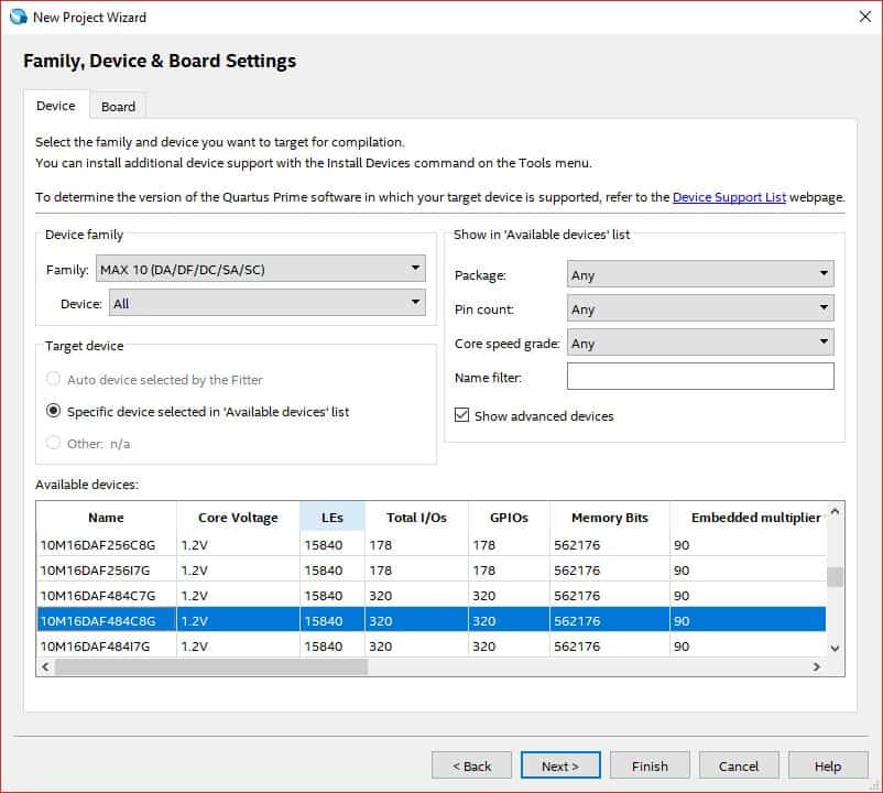
Click Next till you see the ‘Family, Device and Board Settings’ tab. In Boards select ’10M16DAF484C8G’ (select corresponding 10M50 part if your Telesto is of 10M50 variant) and click Next. Again, click Next and finally Finish.
Step 4:
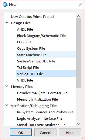
Go to Files->New, Select Verilog HDL file from the list and click OK.
Step 5:
Copy the following code in the .v file and save it with the name ‘telesto_vga.v’.
VGA has five signals i.e. red, green, blue, hsyncandvsync. hsync and vsyncare digital signals that are used as timing synchronization signals for the monitor. Whereas red, green and bluesignals are analog signals carrying pixel data. For 640 x 480 resolution, a mod-800 counter (hcount) is used to control horizontal timing and a mod-525 counter (vcount) is used to control vertical timing.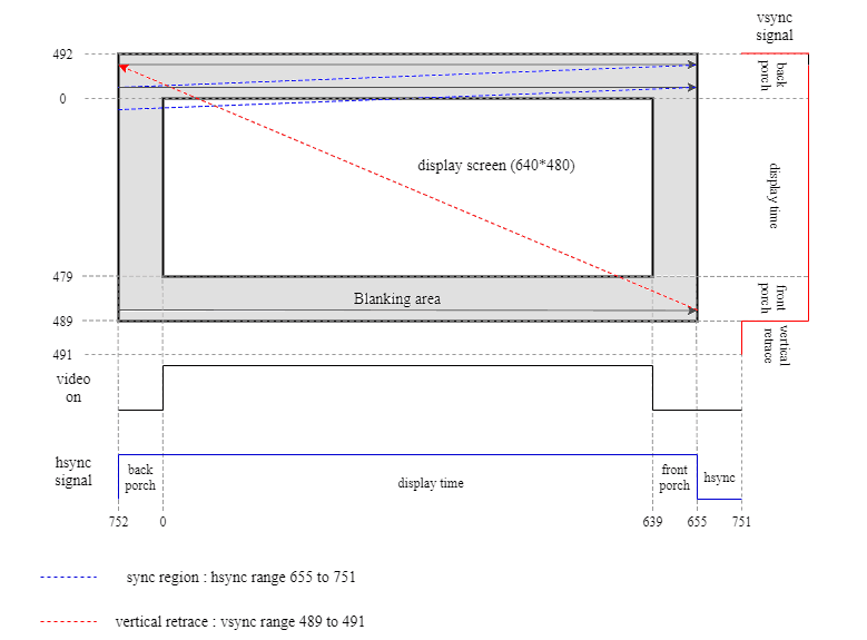
The image depicts the values of hsync and vsync signals corresponding to the value of hcount and vcount. The screen is scanned horizontally first. Once it reaches the end, it goes to next line and again the same procedure is followed. When it reaches the last line, vcounter rolls back to starting point. The values of hcount and vcount are derived from VGA timing standard for 640×480@60Hz resolution.
The values of hcount and vcount denote the current pixel coordinates on screen. So, in the RTL code, the values to red, green and blue signals are given for a particular hcount and vcount value (i.e. for different coordinates of screen).
For displaying various colours, logic is implemented to drive different values to red, green and blue pins of VGA for different pixel ranges. Depending on the combination of these 3 signals, different colours can be displayed. The digital values of red, green and blue signals are converted into analog values by the resistor ladder DAC inside VGA Expansion Module.
The screen is divided into 8 columns and each column displays different colour according to the value given to red, green and blue registers. The columns are divided according to the value of hcount (vertical range remains same for each colour).
`timescale 1ns / 1ps
module telesto_vga(
  input clock,
  output reg [2:0 ] red,
  output reg [2:0 ] green,
  output reg [1:0 ] blue,
  output reg hsync,
  output reg vsync
);

reg [9:0] hcount = 0;
reg [9:0] vcount = 0;
reg [1:0] counter = 0;
reg enable;

always @ (posedge clock)
begin
  if (counter == 3)
  begin
    counter <= 1'b0;
    enable <= 1'b1;
  end
  else
  begin
    counter <= counter + 1'b1;
    enable <= 1'b0;
  end
end

always @(posedge clock)
begin
  if (enable == 1)
  begin
    if(hcount == 799)
    begin
      hcount <= 0;
      if(vcount == 524)
        vcount <= 0;
      else
        vcount <= vcount+1'b1;
    end
    else
      hcount <= hcount+1'b1;


  if (vcount >= 490 && vcount < 492)
    vsync <= 1'b0;
  else
    vsync <= 1'b1;

  if (hcount >= 656 && hcount < 752)
    hsync <= 1'b0;
  else
    hsync <= 1'b1;
  end
end

always @ (posedge clock)
begin
  if (enable)
  begin
    if (hcount < 80 && vcount < 480)
    begin
      green <= 3'b111;
      blue <= 2'b11;
      red <= 3'b111;
    end
    else if (hcount < 160 && vcount < 480)
    begin
      green <= 3'b111;
      blue <= 2'b00;
      red <= 3'b111;
    end
    else if (hcount < 240 && vcount < 480)
    begin
      green <= 3'b111;
      blue <= 2'b11;
      red <= 3'b000;
    end
    else if (hcount < 320 && vcount < 480)
    begin
      green <= 3'b111;
      blue <= 2'b00;
      red <= 3'b000;
    end
    else if (hcount < 400 && vcount < 480)
    begin
      green <= 3'b000;
      blue <= 2'b11;
      red <= 3'b111;
    end
    else if (hcount < 480 && vcount < 480)
    begin
      green <= 3'b000;
      blue <= 2'b00;
      red <= 3'b111;
    end
    else if (hcount < 560 && vcount < 480)
    begin
      green <= 3'b000;
      blue <= 2'b11;
      red <= 3'b000;
    end
    else if (hcount < 640 && vcount < 480)
    begin
      green <= 3'b000;
      blue <= 2'b00;
      red <= 3'b000;
    end
    else
    begin
      green <= 3'b000;
      blue <= 2'b00;
      red <= 3'b000;
    end
  end
end
endmodule
Step 6:
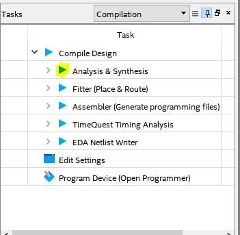
Click on ‘Analysis & Synthesis’ from task menu.
Step 7:
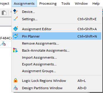
Go to Assignments -> Pin Planner.
Step 8:
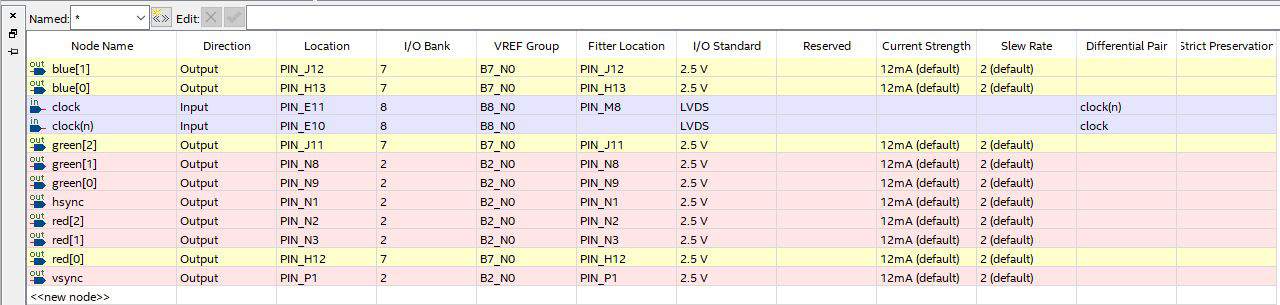
Copy the following pins configuration in the pin planner and then close the pin planner.
Step 9:
Compile your code again. Open Quartus Programmer by clicking Program Device.
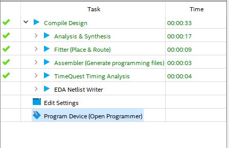
Do not program Teleso yet. The connections for VGA should be set up and ready before programming.
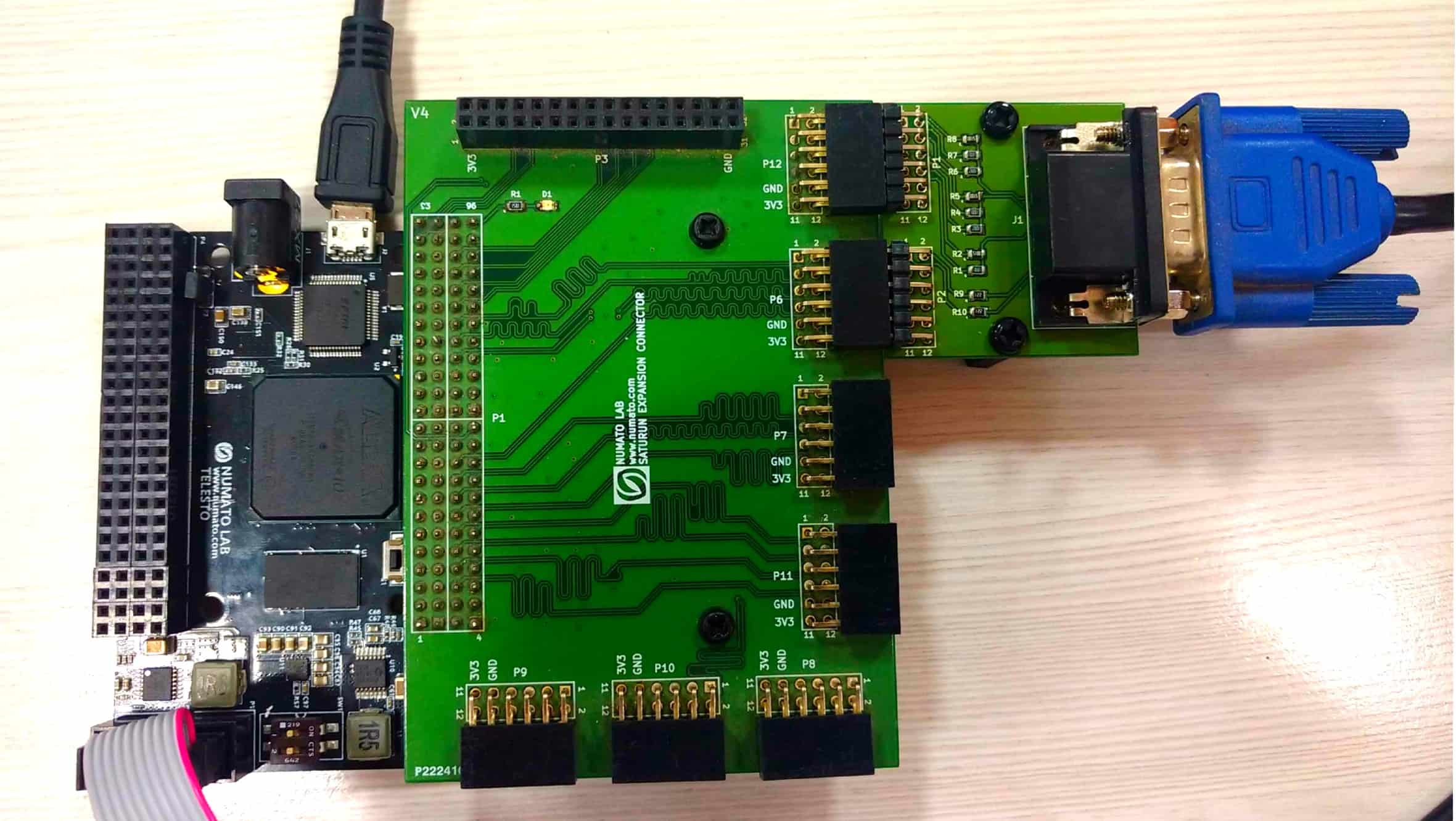
Step 10:
Power off the Telesto board. Connect the Saturn IO Breakout Module to ‘Header P5’ of Telesto, and the VGA module to ‘Header P12 & P6’ of Saturn IO Breakout Module. Connect VGA cable to the VGA module and also to the monitor on which the output is desired.
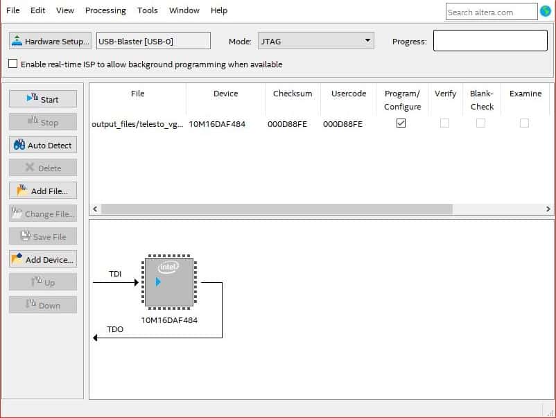
Step 11:
Make sure you have connected Telesto with USB Blaster JTAG and powered it up before attempting to program it. You might need to go to “Hardware Setup…” to choose your JTAG hardware. Click “Start” and wait for the device to get programmed.
Once Telesto is programmed, you should see the following output on the monitor. You can change the code and observe different outputs!
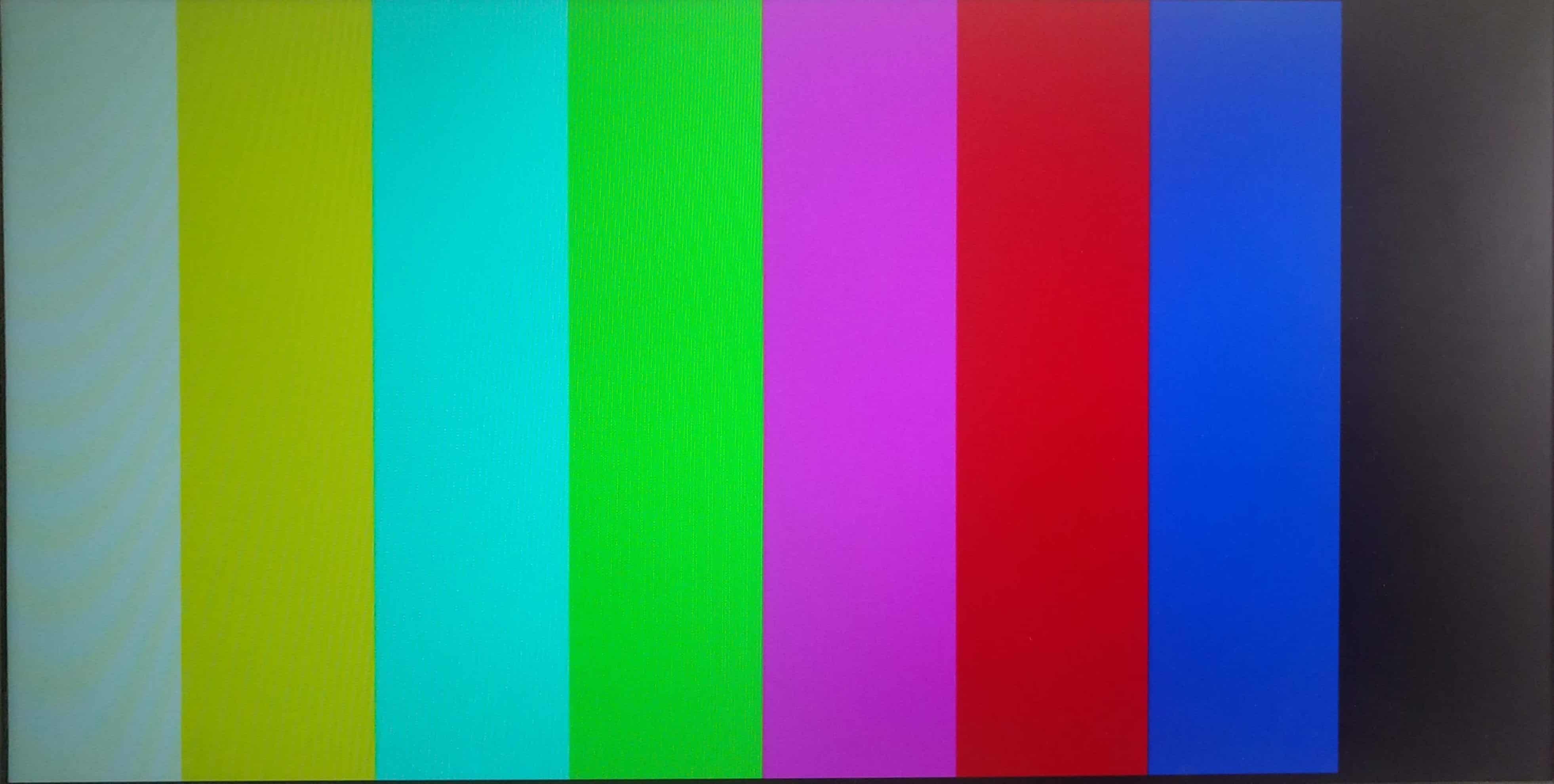
So, that was it! Keep tinkering with the code to get different patterns on the monitor!