Introduction:
PCI Express is a serial expansion bus standard operating at multi-gigabit data rates. It is the third generation, high performance I/O bus which is used for interconnecting peripheral devices. PCI Express provides higher rate of data transfer and lower latency compared to the older PCI and PCI-X technologies which implemented parallel I/O bus. Each device which is connected to the motherboard via PCI Express link actually has a dedicated point-to-point connection and as it is not sharing the same bus, it doesn’t have to compete for bandwidth. PCI Express is based on the point-to-point topology where there are dedicated serial links connecting every device to the root complex. This article implements a simple design to demonstrate how to write and read data to Galatea PCI Express Spartan 6 FPGA Development Board which acts as a PCI Express endpoint device. Lets get started!
Hardware required:
- Host PC with Ubuntu 14.04 or Windows (Ubuntu preferred)
- Galatea PCI Express Spartan 6 FPGA Development Board
- Xilinx Platform Cable USB II (JTAG cable)
Software required:
- Xilinx ISE 14.7
- RW-Everything (for Windows host)
Step 1:
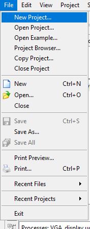
Open Xilinx ISE, click File -> New Project.
Step 2:
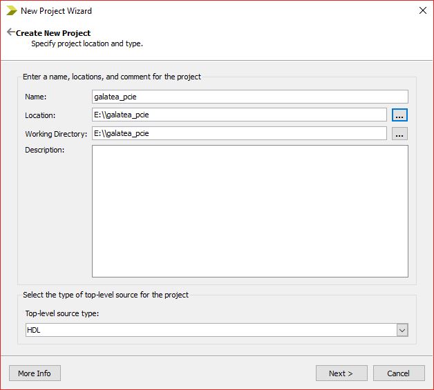
Enter Project Name and Location and click next without making any changes till you see ‘Project Settings’ tab.
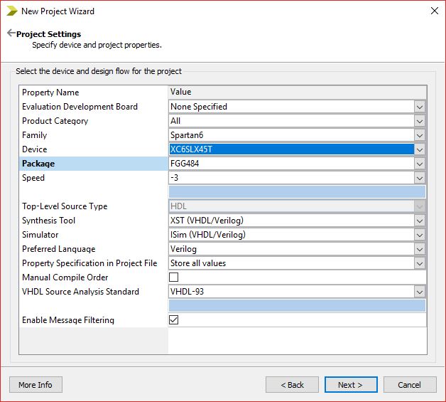
Step 3:
In ‘Project Settings’ tab, select ‘Family’, ‘Device’, ‘Package’ and ‘Speed’ as shown below. Click Next and Finish to create project.
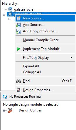
Step 4:
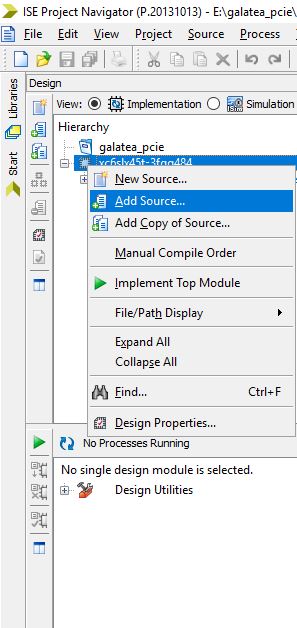
Right-Click ‘xc6slx45t-3fgg484’ and select New Source.
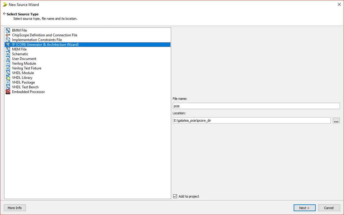
Step 5:
Select ‘IP’ in ‘Select Source Type’ tab, and give file name as pcie.
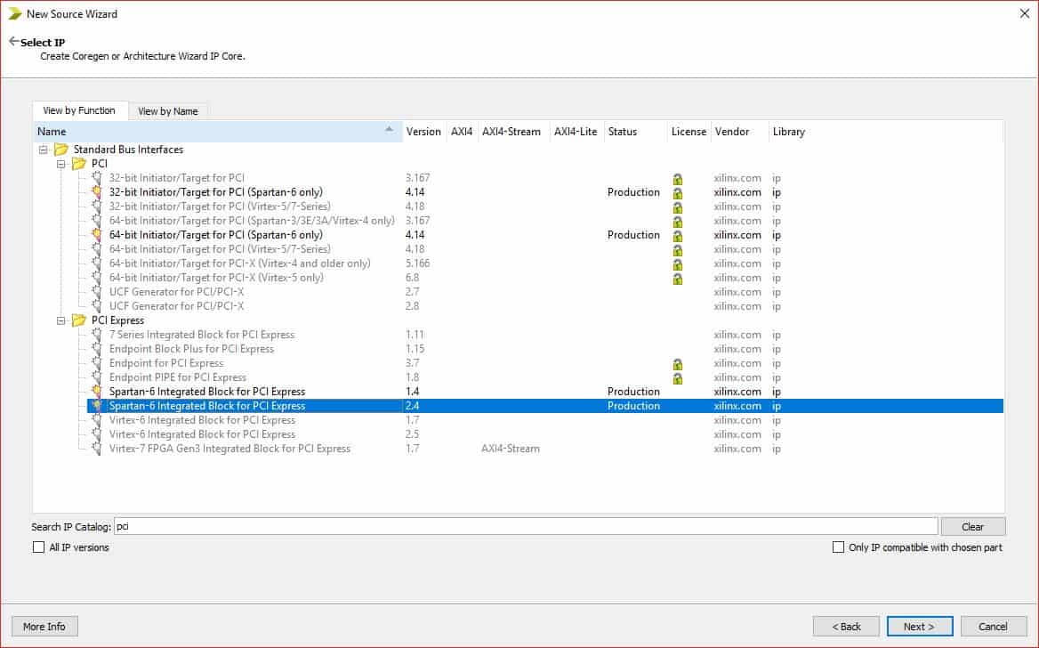
Step 6:
Select ‘Spartan-6 Integrated Block for PCI Express’ in ‘Select IP’ tab. It will open the IP settings for customisation.
Step 7:
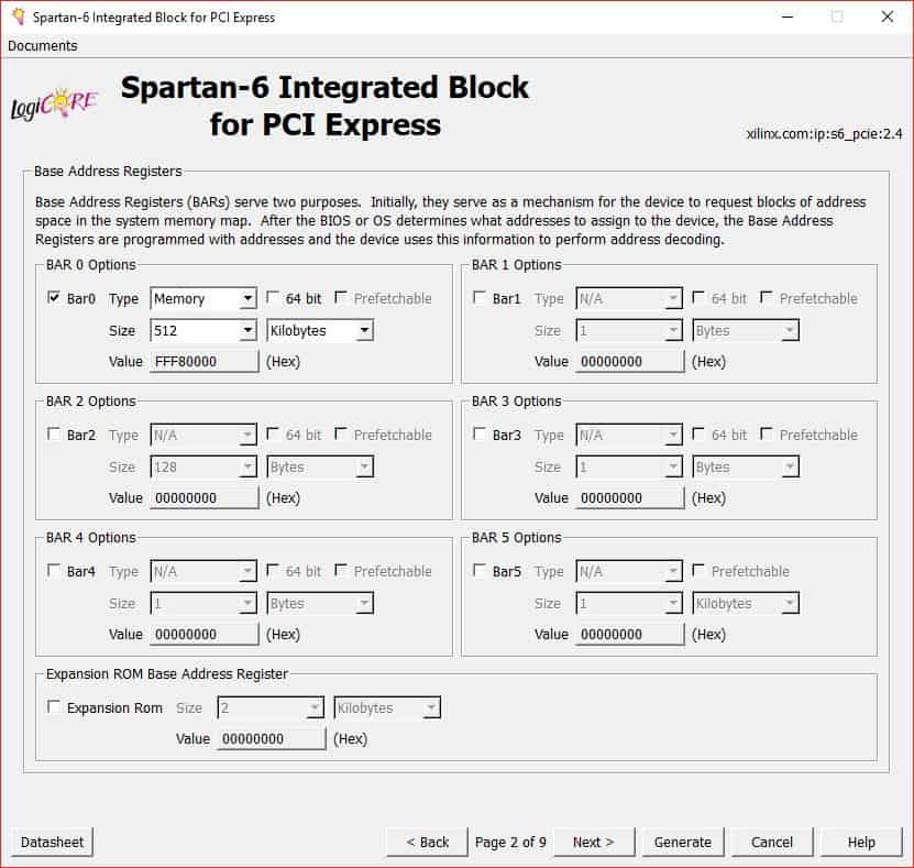
Click ‘Next’and in ‘Base Address Registers (BARs)’ tab, Select ‘BAR0’ memory size as ‘512 Kbs’ as shown below, then click next and generate. No need to change anything in the rest of the tabs.
Step 8:
Right-Click ‘xc6slx45t-3fgg484’ and select Add Source.
Step 9:
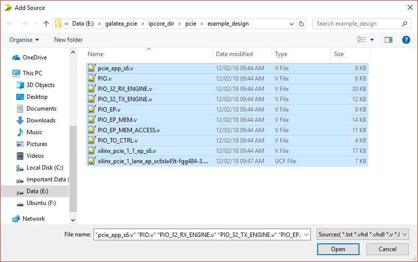
From ‘..galatea_pcie/ipcore_dir/pcie/example_design’ directory, Select all the files and add them.
Step 10:
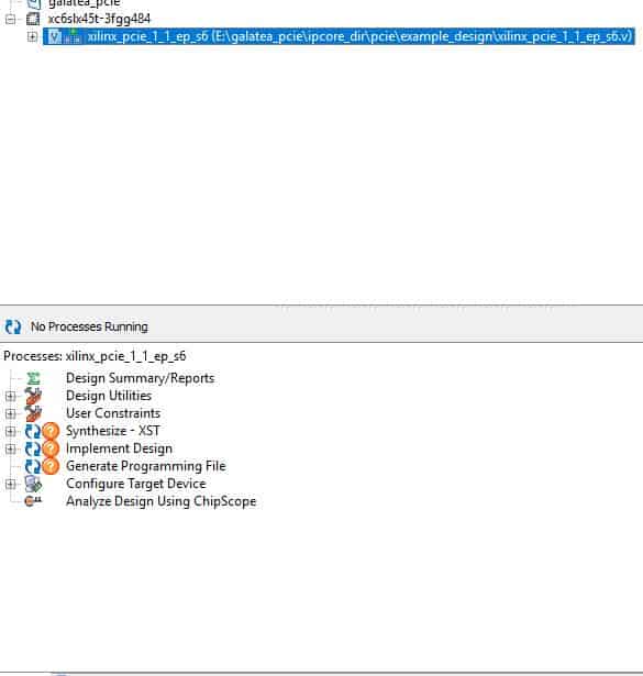
Select Top Module and click ‘Synthesize- XST’, followed by ‘Implement Design’ and ‘Generate Programming File’.
Step 11:
Now bin file is ready, ‘.mcs’ file is needed for Flash Programming. For this, follow the steps in ‘Configuring Galatea using JTAG‘ and then follow the steps here for programming SPI flash.
Step 12:
Once the device is programmed, test it on a Windows or Linux machine.
Communicating with Galatea via PCI Express on Linux Machines:
Step 1:
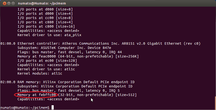
Download the complete pcimem application code zip file and unzip it in a specific location. Go to the command line terminal and check the PCIe base address by using the command
“lspci -vv” the output of the command is shown below. Make sure the Galatea Board is inserted correctly into the PCIe Slot of host system’s motherboard. If the host is unable to detect Galatea (which should show up as “RAM memory: Xilinx Corporation” as in the image below), insert it again properly and do a soft-reset.
Step 2:
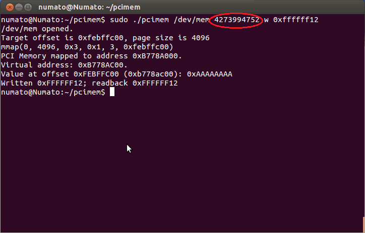
In command line terminal, open the path where you saved ‘pcie application code’. First compile the C program by using the command “make”. Once it is compiled successfully, use the following command:
sudo ./pcimem /dev/mem 4273994752 w 0xffffff12
Here,
4273994752: indicates the base address + offset, it is the address to which write is performed and it is the decimal value of hex: 0xfebffc00 (in the above image)
w: indicates whether it is word, byte or half word.
0xffffff12: 32-bit data value for write purpose.
Observe the following output indicating that the 32-bit data has been written to the specified address and read back from it. If the written data matches the data read, it means data is written successfully.
Communicating with Galatea via PCI Express on Windows Machines:
Step 1:
For Windows machine, use RW-Everything software to write data.
Step 2:
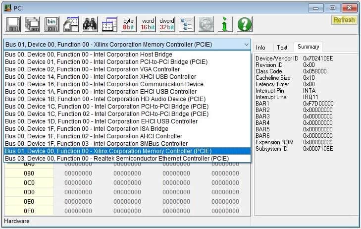
Insert Galatea board in PCIe slot of host system’s motherboard. Open RW-Everything, Click PCI Devices. It will open PCI Devices.

Step 3:
Select Xilinx PCIe Device from drop-down list.
Step 4:
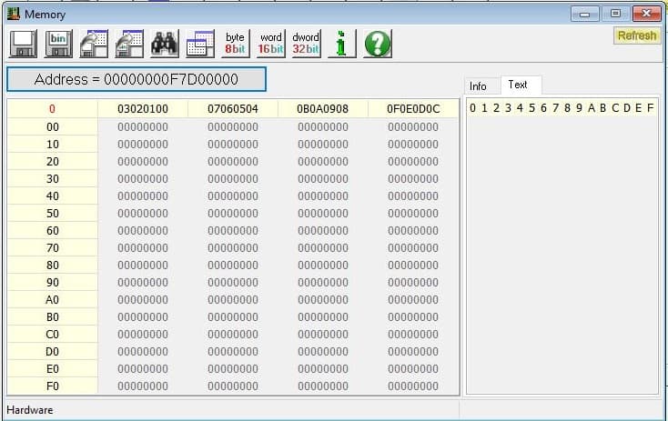
Locate the BAR Address from the addresses on the left-side.
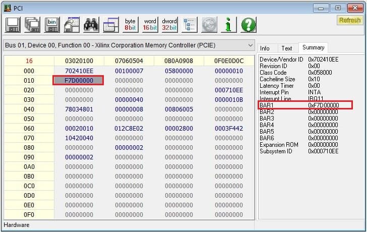
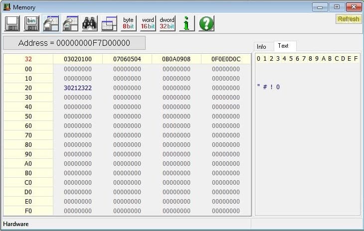
Step 5:
Double-click to open the BAR Address and select any one of the address bit and write some data to it. The data is retained even if you close and open the application indicating that the write operation is successful.