Intercore SDK Framework
The Numato Lab Intercore SDK is a framework for communicating from a host to Numato Lab FPGA boards such as the Mimas A7, Narvi, Skoll, Styx, Proteus, Callisto K7, etc. Intercore SDK accelerates the development by providing an intuitive way of transferring data into and out of the FPGA. The Intercore SDK framework acts as a standard AXI4 Memory Mapped Master, which can control AXI4 compliant slaves and use existing AXI4 infrastructure provided by Xilinx Vivado. This feature makes the Intercore SDK Framework very powerful. Users can use most, if not all, IP cores that support AXI interface and read/write to memory and memory-mapped registers on the devices directly from host PC. There is no need for any microprocessor (such as Microblaze), though Intercore SDK can also work alongside Microblaze or any other AXI Master. This gives users a high degree of flexibility in their designs. The Intercore SDK Framework supports both USB 2.0 and USB 3.0 based Numato Lab FPGA boards.
Now that we have explained in detail what the framework does, let’s jump right into the tutorial. In this article, we’ll help you get started with the Intercore SDK Framework using the Mimas A7 board.
Prerequisites:
To work with the Intercore SDK Framework, it is necessary to set up the development environment and manage prerequisites. This article uses the Numato Lab Mimas Artix 7 FPGA Board as an example but the steps will be similar for other 7-Series boards such as Neso, Proteus, etc.
Hardware:
- Mimas Artix 7 FPGA Module
- Xilinx Platform Cable II USB (not mandatory, but preferred for easier development)
- USB 2.0 Type-B for USB communication with the host
Software:
- Xilinx Vivado 2018.2 or higher
- Microsoft Windows 10
- FTDI FT_Prog
Download and install the Vivado Board Support Package files for Mimas A7 from here. Follow the README.md file on how to install Vivado Board Support Package files for Numato Lab boards. You may skip this step if you have already installed the Vivado Board Support Package files for Numato Lab boards in the past while following other articles.
Please get the Intercore SDK Release package by placing a request via the contact page. Extract the zip file to a convenient location. After extracting, a folder named intercore-sdk with the following directory structure should have been created:
intercore-sdk (root directory of the package)
   |__doc      : Intercore SDK documentation.
   |__driver   : EEPROM configuration files.
   |__examples : Example projects and prebuilt bitstreams for Intercore SDK supported Numato Lab FPGA boards.
   |__hdl      : Intercore SDK IP core package for Vivado.
   |__sdk      : Host libraries for Intercore SDK for multiple languages are available in this directory. Check out the README.md file inside the directory for more information.
Driver Installation
If the drivers for Mimas A7 (or Neso, Skoll, Styx, etc) are required to be installed, then download the drivers for the respective boards from the Numato Lab website and install them.
Intercore SDK Setup
Intercore host SDK has to be set up before it can be used for communication with the Intercore SDK framework running on Mimas A7.
The steps below will get you started with running Intercore SDK quickly.
- Configure the FTDI FT2232H User Channel:
- The User Channel of your FPGA board (Channel A of Mimas A7, for example), should be configured to
245 FIFOhardware mode andD2XXdriver.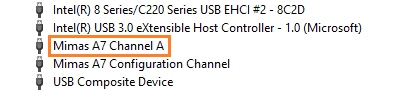
- This is only required if your board is a USB 2.0 board, i.e, one of these:
[Narvi, Mimas A7, Neso, Skoll, Styx]. If your board supports USB 3.0, for example[Proteus, Callisto K7, Nereid]then skip these configuration steps. - Download and install
FT_Progutility from FTDI Website - Locate the EEPROM configuration file for your Numato Lab FPGA device in the directory
driver/eepconfig/and program the configuration to the hardware using FT_Prog.
- The User Channel of your FPGA board (Channel A of Mimas A7, for example), should be configured to
- Prebuilt bitstreams for all the example projects are provided in the
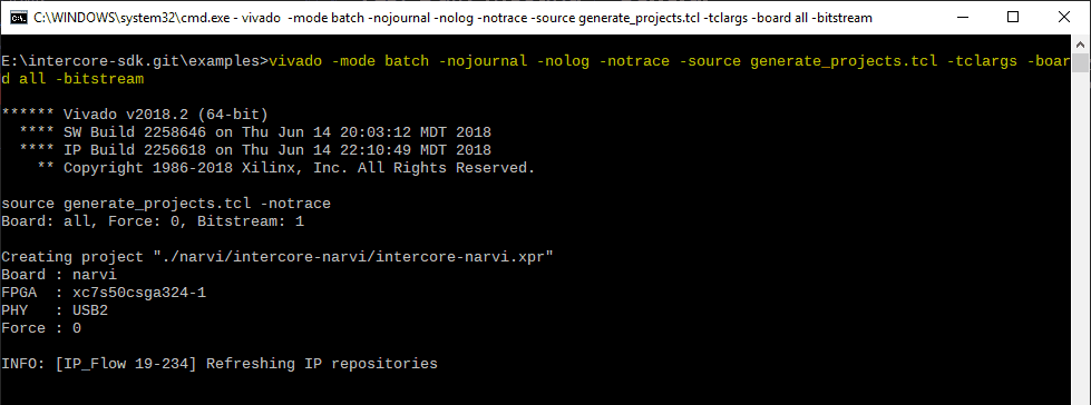
examplesdirectory. Program the Numato Lab FPGA board using the provided bitstream. Or, if you wish to generate fresh bitstream files yourself, go to the"examples"directory. Open terminal, command prompt, or PowerShell in the"examples"directory and from the same directory, run thegenerate_projects.tclscript through Vivado using this command:
>> vivado -mode batch -nojournal -nolog -notrace -source generate_projects.tcl -tclargs -board all -bitstreamNote: This command will automatically create Vivado projects for all the boards, and will synthesize, implement and generate bitstreams for all of them. Thus this command takes a lot of time to finish. If you wish to skip generating a bitstream automatically (and prefer to manually open the generated project and then create the bitstream, then remove the option -bitstream from the above command. It is also possible to create projects for specific boards only instead of all the boards. Use something like -tclargs -board neso to create a project just for the Neso board without generating bitstream. Refer to the README file inside examples the directory for further details.)
- Once the Vivado projects have been created and bitstream generated in the previous step, locate the subdirectory that corresponds to your Numato Lab FPGA board in the
examplesdirectory. Open thebitstreamdirectory and program your Numato Lab FPGA device using either the .bin or .bit file available in the directory. For example, for the “Mimas A7” board, the bitstreams would be located in theexamples\mimas-a7\bitstreamsdirectory. - Set up MinGW, Visual C++ or other build tools in your host system. Refer to the README file in the
sdkdirectory for more information. - Test the generated test executable as described in the next section below.
Building Host Test Applications
Instructions for building Test/Demo host applications.
The Intercore SDK uses Meson & Ninja for easier builds of C/C++ and Java Intercore SDK libraries. Both MinGW and MSVC compiler toolchains are supported.
Python
This is the preferred option since it doesn’t require any compiler toolchain to be installed for testing. If you don’t have MinGW or Microsoft Visual Studio build environments set up, then just download and install the latest Python distribution (prefer >= 3.5). Go to sdk/python directory, open the command prompt in the same directory and run the Python test script as:
>> python ic-test.pyIf the python executable is not in PATH, then provide the full path to the python executable like this:
>> C:\Python37\python.exe ic-test.pyMinGW32 or MinGW64
Make sure the GCC from MinGW32 or MinGW64 is the first compiler in the PATH before any other compiler. Prefer the MSYS2 packaged MinGW 32-bit or 64-bit GCC. Run the following command in sdk\test directory.
>> meson build-mingw && ninja -C build-mingwMSVC Command Line
Make sure the Microsoft compiler cl.exe is the first compiler in PATH before any other compiler. Meson will automatically use it for the build. Run the following command in sdk\test directory.
>> meson build-msvc && ninja -C build-msvcMicrosoft Visual Studio Project
Open the intercore.sln solution in the directory sdk/msvc in Microsoft Visual Studio 2017 and build & run the solution.
Hardware design using Vivado
The following steps will walk you through creating your first design utilizing the Intercore SDK Framework using Xilinx Vivado Design Suite.
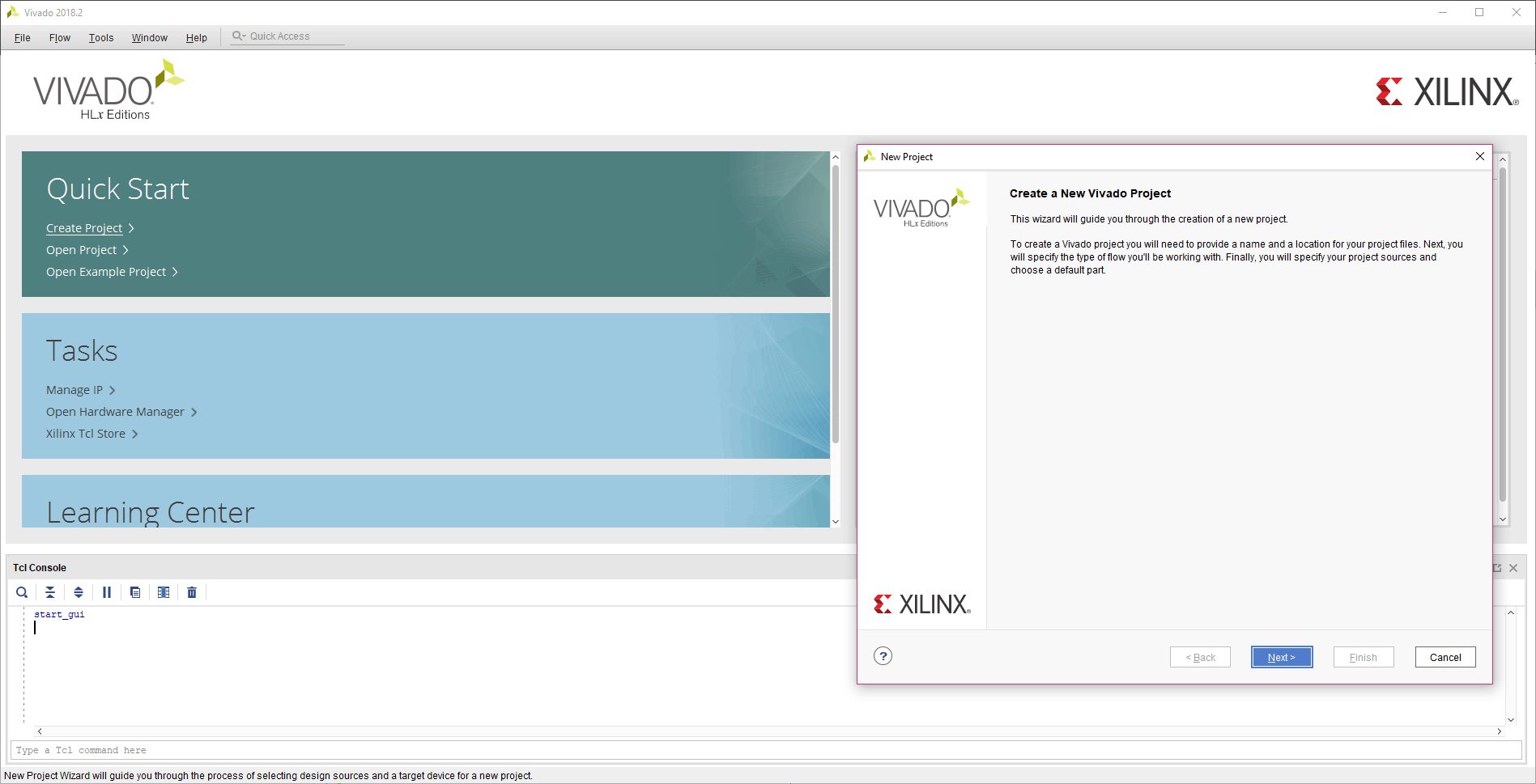
Step 1:
Start Vivado Design Suite, and select “Create New Project” from the QuickStart section. The project wizard will open. Click “Next” to proceed with creating the project.
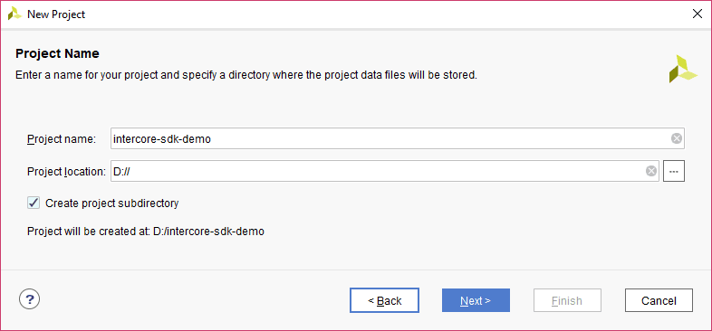
Step 2:
Enter a name and location for the project. This article uses the project name “intercore-sdk-demo” but feel free to name it as per your preference. Select the checkbox “Create project subdirectory” as shown in the image below and proceed with the “Next” button.
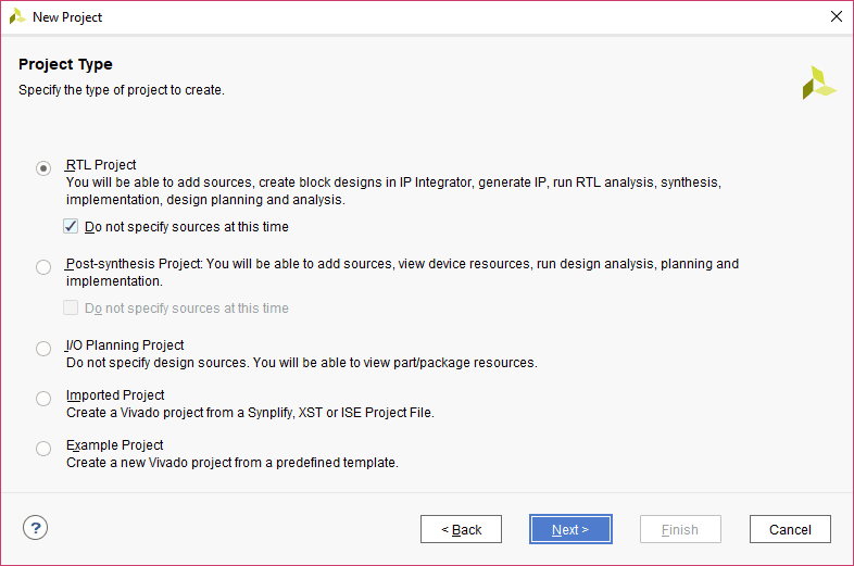
Step 3:
Select “RTL Project” as project type, and select the checkbox as shown below:
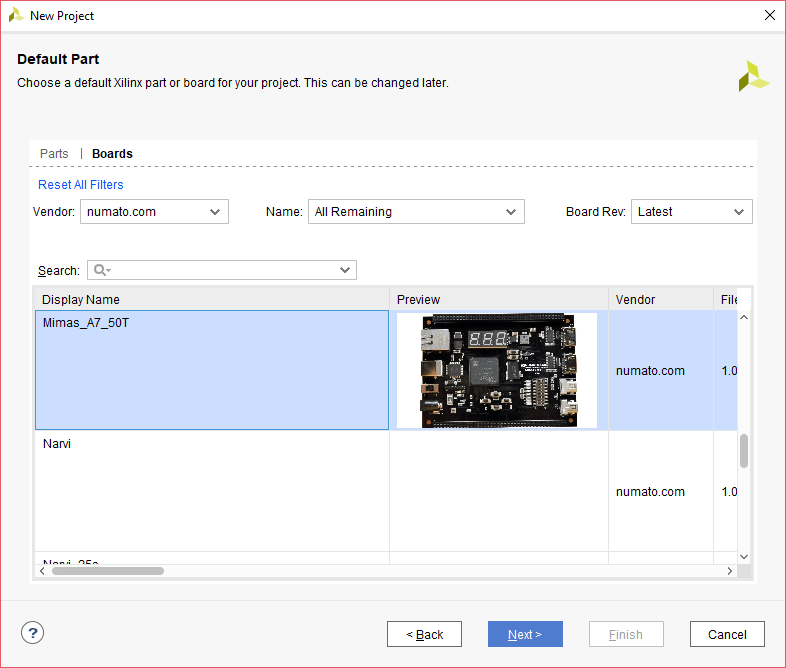
Step 4:
At the “Default Part” step, select the “Boards” tab. Select “Mimas_A7_50T” from the list. If Mimas A7 is not listed, make sure board support files are installed correctly. After selecting the board, click Next, then click Finish. The project will be created.
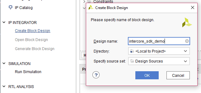
Step 5:
Under Flow Navigator in Vivado window, click “Create Block Design” in IP Integrator. Give a name to the block design. This article used “intercore_sdk_demo” for the block design name. You can use any name as per your preference.
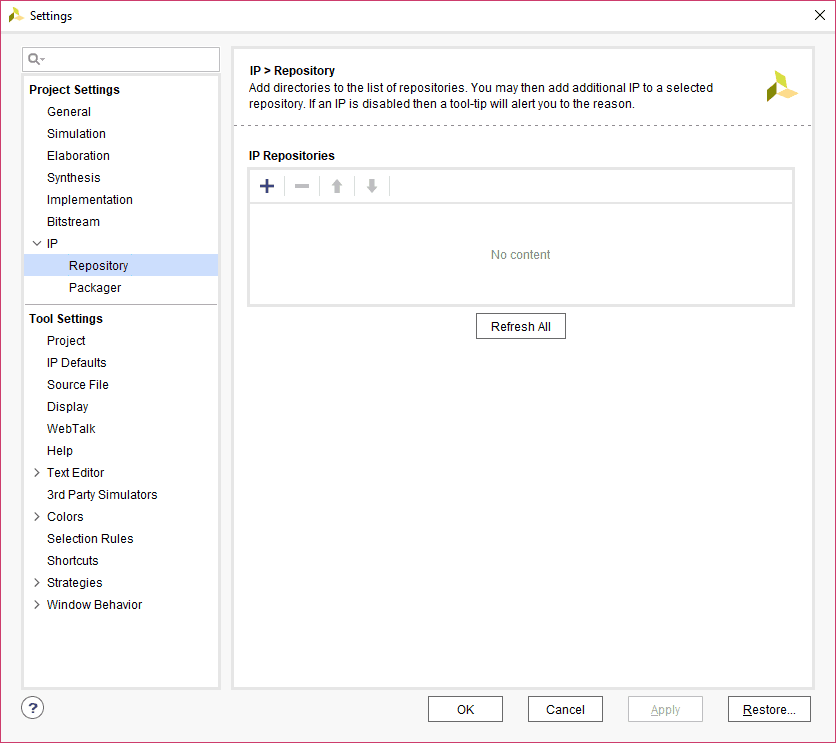
Step 6:
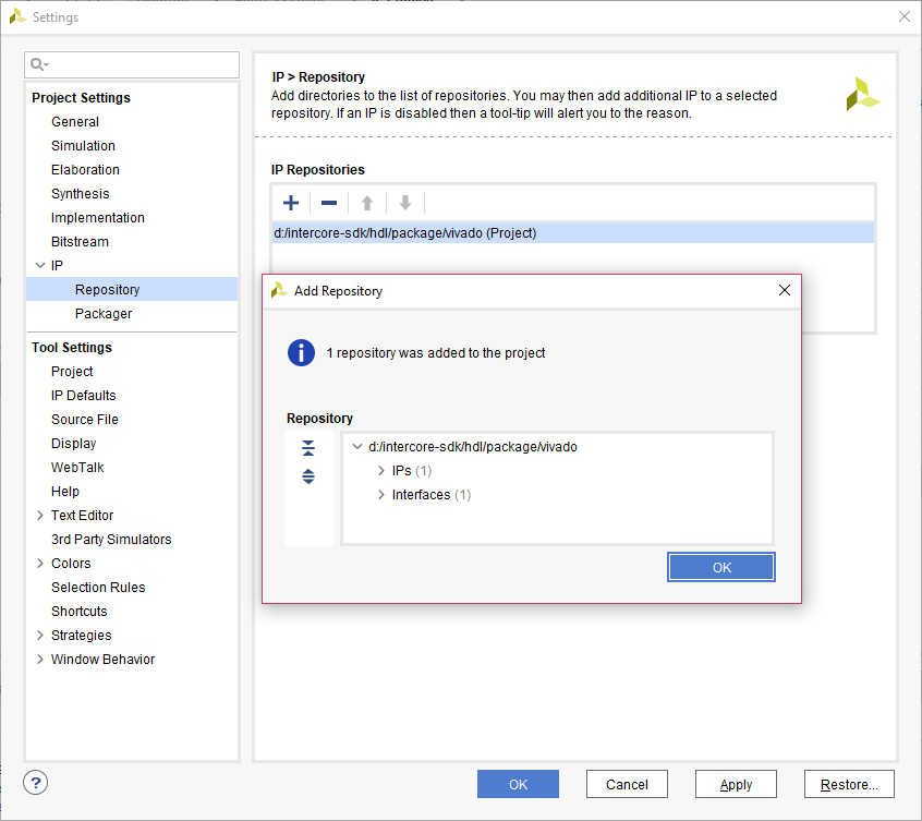
In the Flow Navigator section of the Vivado, click on “Project Settings” under “Project Manager”. In the Project Settings window that comes up, click on the “IP” section, go to “Repository” under the IP section, and click “+” to add the location of custom IPs.
Step 7:
In the IP Repositories window that opens, browse to the directory where you had extracted the intercore-sdk package. Navigate to intercore-sdk\hdl\package\vivado and click “Select”. Vivado will scan the folder for any IPs or interfaces and list them out as shown in the image below. There should be at least 1 IP and 1 Interface detected by Vivado as shown in the image below. Click “OK” in the Add Repository window to confirm, then “Apply”, and finally “OK” in the Settings window to save the project settings.
Step 8:
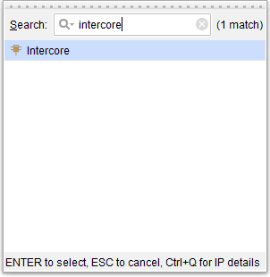
Go to the Diagram window, right-click and select “Add IP” from the popup menu. Search for Intercore. Add it to the block design by double-clicking it.
Step 9:
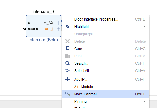
Right-click on the “host_if” port of Intercore block and select “Make External”. This will make the “host_if” port as an external port of the top-module. All communication between the host PC and the FPGA happens via this port.
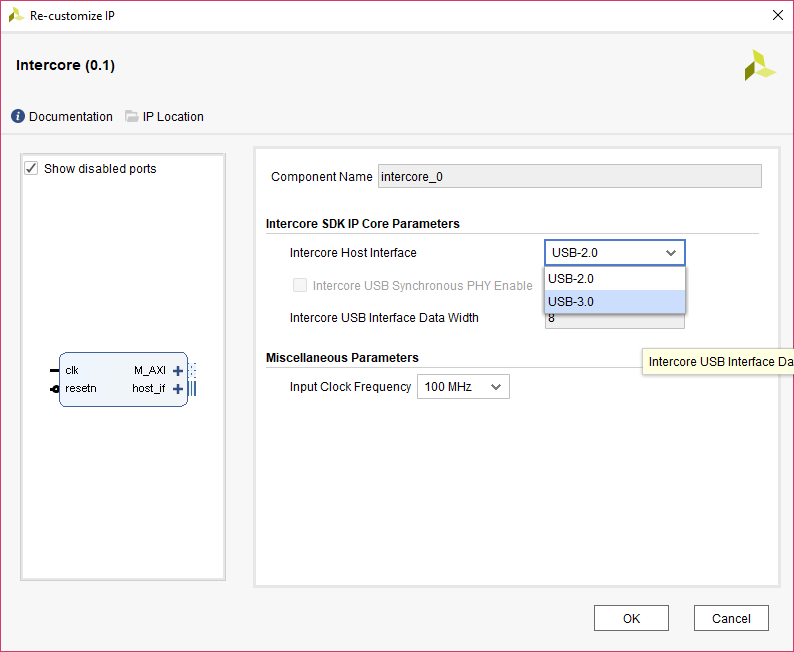
If you’re using USB 3.0 boards, for example, Callisto K7 or Proteus, you will have to customize the Intercore IP. Double click on the Intercore IP and under Intercore SDK IP Core Parameters, select Intercore Host Interface as USB 3.0 as shown in the image below.
Step 10:
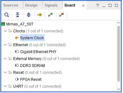
In the Block Design Window, select the “Board” tab on the top. The default peripherals available for the selected board (Mimas A7 in this case) will be displayed. Drag and drop “System Clock” into the diagram window. This will add a Clocking Wizard “clk_wiz_0” block in the design.
Step 11:
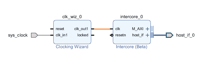
Connect “clk_out1” from Clocking Wizard to “clk” of Intercore block.
Step 12:
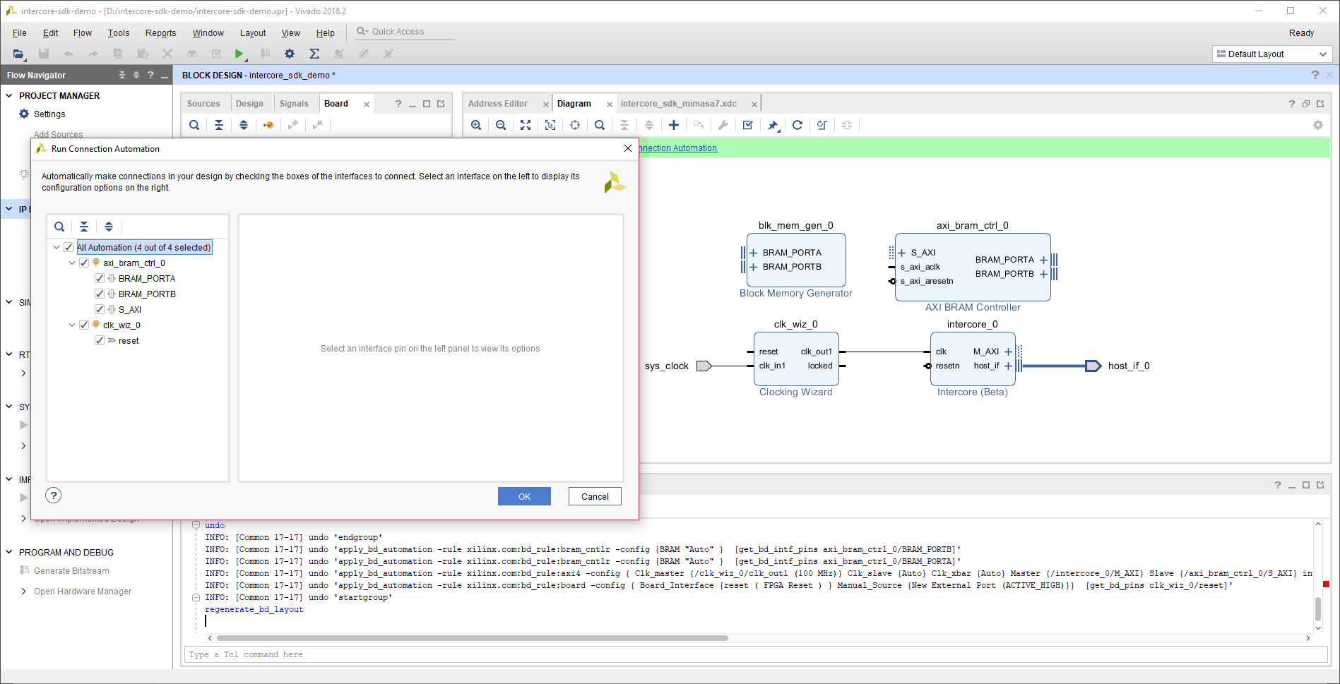
Add “AXI BRAM Controller” IP to the design. Click “Run Connection Automation” on the green bar on top of the design area. Check “All Automation” and click “OK”.
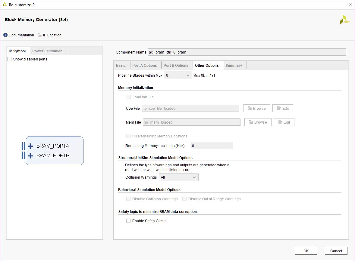
After the “Run Connection Automation” step, a Block Memory Generator IP will be added to the block design by Vivado. This Block Memory Generator IP core requires some further configuration. Double-click this IP core block to customize it. In the customization window that appears, go to the “Other Options” tab and disable “Enable Safety Circuit” option as shown below.
Step 13:
Now, click “Run Connection Automation” once again (if there are any connections required/pending). After running the last connection automation, a design similar to the one shown below will be generated. You might need to click “Regenerate Layout” to tidy up the diagram and rearrange it in a better way. As you might notice, “ext_reset_in” has now been connected to the external “reset” signal. This is the final design that will be used in this article.
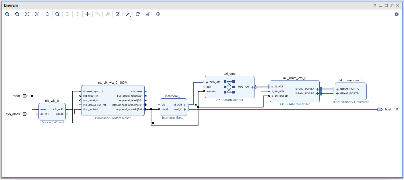
Save the block design.
Step 14:
Add constraints for the host interface port using the following steps. Go to the Project Manager. In the Sources window, right-click anywhere and select “Edit Constraints Sets”. Add a new constraints file named “intercore_sdk_mimasa7.xdc” and save the below contents to the newly created xdc file:
set_property -dict {PACKAGE_PIN Y22  IOSTANDARD LVCMOS33 SLEW FAST} [get_ports {host_if_0_data_io[0]}]
set_property -dict {PACKAGE_PIN Y21  IOSTANDARD LVCMOS33 SLEW FAST} [get_ports {host_if_0_data_io[1]}]
set_property -dict {PACKAGE_PIN AB22 IOSTANDARD LVCMOS33 SLEW FAST} [get_ports {host_if_0_data_io[2]}]
set_property -dict {PACKAGE_PIN AA21 IOSTANDARD LVCMOS33 SLEW FAST} [get_ports {host_if_0_data_io[3]}]
set_property -dict {PACKAGE_PIN AB21 IOSTANDARD LVCMOS33 SLEW FAST} [get_ports {host_if_0_data_io[4]}]
set_property -dict {PACKAGE_PIN AA20 IOSTANDARD LVCMOS33 SLEW FAST} [get_ports {host_if_0_data_io[5]}]
set_property -dict {PACKAGE_PIN AB20 IOSTANDARD LVCMOS33 SLEW FAST} [get_ports {host_if_0_data_io[6]}]
set_property -dict {PACKAGE_PIN AA18 IOSTANDARD LVCMOS33 SLEW FAST} [get_ports {host_if_0_data_io[7]}]
set_property -dict {PACKAGE_PIN V22  IOSTANDARD LVCMOS33 SLEW FAST} [get_ports host_if_0_txe_n]
set_property -dict {PACKAGE_PIN W21  IOSTANDARD LVCMOS33 SLEW FAST} [get_ports host_if_0_rxf_n]
set_property -dict {PACKAGE_PIN W22  IOSTANDARD LVCMOS33 SLEW FAST} [get_ports host_if_0_wr_n]
set_property -dict {PACKAGE_PIN AA19 IOSTANDARD LVCMOS33 SLEW FAST} [get_ports host_if_0_rd_n]
Step 15:
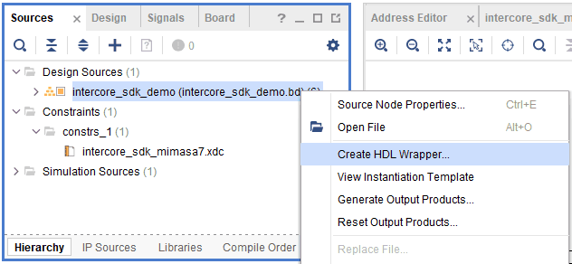
Right-click on the design file (with .bd extension) in the sources window and select “Create HDL Wrapper” from the popup menu. Click OK in the dialog window that appears, to finish generating the wrapper.
Step 16:
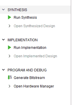
Now, double click on “Generate Bitstream” under the “PROGRAM AND DEBUG” section to synthesize, implement and generate the bitstream.
Step 17:
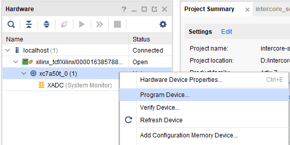
Program the generated bitstream to Mimas A7 using the following steps. Make sure the Xilinx Platform Cable is connected to Mimas A7. Click “Open Target” under “Open Hardware Manager” in the “Program and Debug” section of Flow Navigator in Vivado. Right-click xc7a50t_0 and click “Program Device…” as shown in the image below. Click “Program” and wait for the programming to finish. It is also possible to program Mimas A7 without using Xilinx Platform Cable. Refer the “Configuring Mimas A7 using Tenagra” section of Mimas A7 User Manual on how to do that.
Communication with Host
Step 1:
Change to the directory where the zip file was extracted. Further, change to the sdk directory.
Step 2:
If the compilation had succeeded during the SDK setup, there would be an executable named test_prog.exe inside the build-msvc32-release (or build-msvc64-release) folder. Run the executable from the sdk folder:
>> build-msvc64-release\test_prog.exe
The number of boards connected to the host system and detected by the Intercore SDK library will be displayed. Here, there is only one device connected, so only one device is displayed as shown in the image below. Hence enter the index ‘0’ corresponding to the Mimas A7 board to start the test.
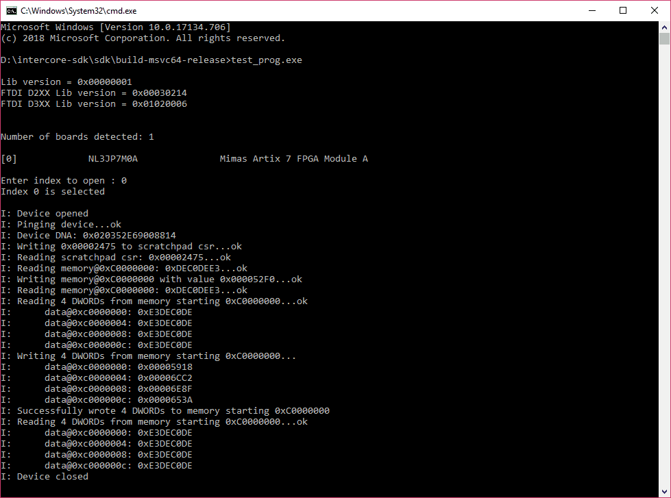
The code first pings the Intercore SDK framework for presence and response. If the ping succeeds, the code then reads the Device DNA of the FPGA on Mimas A7. Once these steps are completed successfully, it proceeds with writing Block RAM with data and then reads back from the Block RAM to verify that contents match, which ideally should match if everything worked as expected.
Congratulations! You just communicated with FPGA using the Intercore SDK framework! Refer to the Intercore SDK User Manual inside the intercore-sdk\doc and the source code of the test application to learn more about the Intercore SDK API.