Introduction
Numato Lab’s Relay modules implement an easy to use human readable set of commands. The greatest advantage of this command set is that the commands and the command behavior are same irrespective of the interface being used. So learning a single set of commands will help a user work with USB, Ethernet, WiFi or any interface for that matter. Of course, there are interface specific commands but all primary commands are exactly same. The primary command set can be divided in to two groups. The commands that works with individual Relays, and the commands that can work with multiple Relays. The singular commands such as relay on or relay off are very intuitive and fun to use but they tend to get inefficient as the number of Relays that needs to be managed goes up. For example, to turn ON 64 relays using relay on command, a user will end up having to send 64 individual commands. This certainly is difficult if the user is manually entering the commands, and neither is this very efficient for even a script or application. readall/writell commands can be a huge time saver in such situations. readall/writell commands can accept data for multiple Relays and apply them all in a single command execution cycle. These commands are considered to be advanced commands and are a bit complex to understand and use. This article attempts to break it down and make it easily understandable with the help of examples.
On relay modules the readall/writeall commands are implemented as sub-commands to the relay command. So these commands are always invoked as part of relay command.
Applicable Products*
* Some exclusions apply. Please see the product specification/user manual for commands and features supported by individual products.
Prerequisites
Some introductory knowledge on how Relay modules work and how to send commands to the modules can be very helpful. Basic knowledge on number systems (primarily Hexadecimal and Binary) and conversion between them is strongly recommended.
Using readall Command with Relay Modules
Let’s start with taking a closer look at the readall command. The readall command is used to read the status of all relays present on the device in a single command cycle. readall command for relays is executed by sending the command relay readall . Please note that the readall command does not require any arguments. The device responds to the readall command by sending back a hexadecimal number . The length of the returned number will vary depending on the number of relays on the device. For example, a 8 Channel USB Relay Module will respond to readall command with one byte worth of information, ie; two characters. This is because each bit in the returned number represent the state of one relay. So each character in the response can represent the state of up to four relays. Lets take a look at a real world example. The picture below shows relay readall command executed on a 32 Channel USB Relay Module.
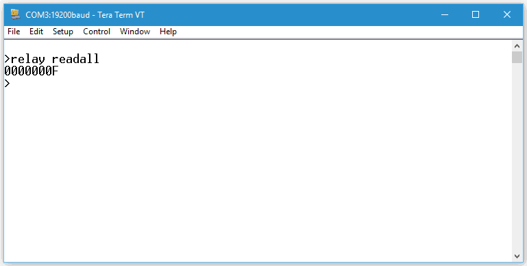
As we can see, the response has eight characters. Considering each character represents the state of four relays, we can see that the whole response can represent the states of 8 x 4 = 32 relays, which is what we would expect from a 32 Channel USB Relay Module. Now the last part of understanding the readall command is to understand how to decode the state of individual relays from the response. This is accomplished by simply converting the response from the device to binary format (remember, the response will be in Hexadecimal format). The conversion can be done manually by using a scientific calculator or if you are writing a program or script you may use conversion functions provided by the specific programming language. For example, when converting the response from the 32 Channel USB Relay Module in the picture above, we will get the result as shown below.
| Hex | Binary (31 – 0) |
| 0000000F | 0000 0000 0000 0000 0000 0000 0000 1111 |
We can see that the higher 24 positions in the binary data are zeros and the lowest four positions are ones. This means that the relays 0 – 3 are in ON state and relays 4 – 31 are in OFF state. In essence, a 1 at any position indicate the relay at that position is in ON state and 0 at any position indicates that the relay at that position is in OFF state.
Using writeall Command With Relay Modules
Just like readall command provides a method to read the status of all relays at the same time, writeall command provides a mechanism to change the state of all relays through a single command. The concept of using writeall command is very similar to readall except that instead of receiving data from the device, writeall command will send data to the device so the relay status can be changed. writeall command for relays is executed by sending command relay writeall <data> where the data represents the relay state data to be sent to the device. The relay state data is always represented in hexadecimal notation. The length of the data will depend on the number of relays on the device, generally one character per four relays present on the device.
Let’s take a look at a practical scenario. Suppose we want to turn ON the four relays on the highest positions on a 32 Channel USB Relay Module. The relay state data for this would look like below in binary format.
| Binary (31 – 0) |
| 1111 0000 0000 0000 0000 0000 0000 0000 |
As we learned with readall command, a 1 at any bit position will turn ON a relay at that position and 0 at any bit position will turn OFF the relay at that position. When this binary data is converted to hexadecimal the result would be 0xf0000000 and this is the value we will be sending to the device as the argument to writeall command. So the complete command to be sent to the device to turn ON the upper four relays would be as follows.
relay writeall f0000000
It is important to note that the 0x part of the hexadecimal notation is stripped off before sending the data to the device.
Now some of you may have noticed what would happen to the relays at the positions from 0 – 23. As you may have guessed it, they will turn OFF if they were already turned ON. If there are relays that are already in a particular state that you would like to preserve, a read-modify-write operation would be necessary. To do so, a readall command is issued to the device to read the current state of all relays and modify the response appropriately using OR or AND operation and written back using writeall command. Let’s reconsider the previous example. Assume that the 32 Channel USB Relay Module had it’s Relay0 turned ON already. If we execute the command relay writeall f0000000 , the upper four relays will turn ON but the Relay0 which is currently in ON state will turn OFF. This is certainly an unintended situation. To avoid that, we need to read the relay states first using readall command and the result will be 00000001. We do an OR operation on this data with the second value f0000000 and the result would be f0000001 . The table below shows the OR operation in hexadecimal and binary format.
| Binary | Hex |
| 11110000 00000000 00000000 00000000 | F0000000 |
| OR | |
| 00000000 00000000 00000000 00000001 | 00000001 |
| = | |
| 11110000 00000000 00000000 00000001 | F0000001 |
Now that we have the resultant data, we can send it to the device by using command relay writeall f0000001. This command will turn ON the upper four relays while keeping the Relay0 in it’s previous ON state.
Conclusion
readall and writeall commands offer very powerful and flexible mechanism to work with large number of relays. While these commands may be slightly more difficult to understand and implement, they will help save a lot of time and effort eventually.
Really nicely explained – thank you.
March 14, 2017 at 12:58 amJust one error, I think the number should be 28, not 24:
“We can see that the higher 24 positions in the binary data are zeros…..”
So, I am I to assume that turning on bit 0 in the low byte turns on relay 0?
Is there a PDF documenting all the commands that the relay responds to?
December 7, 2018 at 3:05 pm