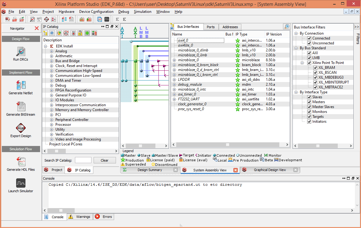
Xilinx EDK is an easy to use application to build Microblaze soft processor based embedded systems on Xilinx Spartan 6 series and newer FPGAs. EDK is in fact a bundle of two applications. The Xilinx Platform Studio and Xilinx SDK. The purpose of Xilinx Platform Studio is to design the Microblaze based system including peripherals, memory etc. Xilinx Platform Studio helps to connect and configure different different aspects of the system visually. The process of designing a system using Xilinx XPS is analogous to building embedded system hardware by connecting processor, memory and peripherals but everything is done in software. A picture of Xilinx XPS in action is below.
 |
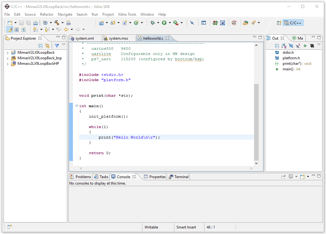 |
While Xilinx Platform Studio helps to build Microblaze based embedded system, Xilinx SDK helps to write firmware that runs on the aforementioned embedded system. Xilinx SDK is an Eclipse based IDE where one can create, build and maintain projects to create firmware for Microblaze. The firmware can be written using C/C++, very similar to writing firmware for any microcontroller out there. The built in toolchain will build your code and generate executable file in ELF format. It is easy to see from the image above that Xilinx SDK is a full fledged development environment.
It is helpful to note that these two tools generate their own set of output files. The most important output file generated by Xilinx Platform Studio is the bit stream which usually has the default file name system.bit. This file represents the whole Micorblaze based system designed using XPS. So this bitstream does not contain the firmware that needs to run on the Microblaze soft processor and thus pretty much useless on its own. The firmware is built using Xilinx SDK. SDK will generate the executable file in ELF format.
During development/debugging phase, the programming tool built in to Xilinx SDK (Xilinx Tools > Program FPGA) can be used to program these files in to the target device. The programming tool will pick up the correct files (.bit and .elf), merge them and program to the FPGA’s SRAM. This is a very straight forward process, thanks to the easy to use FPGA programming tool that is shipped with Xilinx SDK. But the downside though is that you need to have access to a relatively expensive programming cable and still the application cannot be programmed on to the SPI flash device either. Programming the output files on to SPI flash is very important if the device needs to be used outside the development environment since FPGA’s SRAM is volatile.
Before the application can be programmed to the SPI flash, the output files must be merged in to a single file. This can be achieved by using a few simple commandline tools shipped along with Xilinx ISE. These tools are data2mem and promgen and are usually found inside the Xilinx ISE installation folder. Xilinx has provided a batch file to make these tools available at the command prompt so we don’t have to search around and find where exactly these tools are. To make these tools accessible, run the batch file at the command prompt as shown below. the exact location of the batch file may vary depending on your operating system and ISE version. Please make sure to make changes accordingly.
cmd>c:\Xilinx\14.6\ISE_DS\settings64.bat
Now the tools are accessible, we need to go collect a few files, of course including those files we want to merge. We will be needing the following files to perform merging successfully.
- The bit file (.bit) for the Microblaze system (generated by XPS and can be found in the folder SDK\SDK_Export\hw under the XPS project folder)
- The Block ram Memory Map file (.bmm) (generated by XPS and can be found in the folder SDK\SDK_Export\hw under the XPS project folder)
- The executable firmware file (This file can be found in the directory \Debug under the SDK project folder and has .elf extension)
Once all these three images are saved to a folder, we can start merging them. The image below shows all files used for the example here.
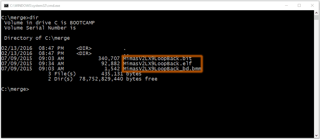
The first command to run is data2mem as shown below. Make sure to replace the file names with your files appropriately.
cmd> data2mem -bm MimasV2LX9LoopBack_bd.bmm -bd MimasV2LX9LoopBack.elf -bt MimasV2LX9LoopBack.bit -w
This command will merge the input files and generate a combined bitstream with name MimasV2LX9LoopBack_rp.bit. This bitstream can be used to program the FPGA SRAM as is using Xilinx Platform Cable USB. But to program SPI flash, a MCS of bin file needs to be generated. The MCS file can be used with Xilinx Platform Cable USB and the bin file can be used with configuration tools available for Numato Lab’s FPGA boards. The command for generating MCS file is as below.
cmd> promgen -w -p mcs -c FF -o download -s 16384 -u 0 MimasV2LX9LoopBack_rp.bit -spi
Command for generating bin file is below.
cmd> promgen -w -p bin -c FF -o download -s 16384 -u 0 MimasV2LX9LoopBack_rp.bit -spi
Make sure to enter correct flash memory size in the above commands (the number after -s switch, in KBytes). If everything goes well, the above commands sill generate MCS or bin file that can be programmed to SPI flash on FPGA development board and the FPGA will be able to boot from SPI flash.
A very detailed real world example of using these tools to generate merged bitstream for programming SPI flash is covered in part 4 of Saturn Linux build tutorial.
fantastic tutorial thank you.
August 2, 2018 at 10:58 amwhen i program my mojo board it does ‘t turn on the DONE LED it means there is something bad with programming the flash .do u have any idea?my flash memory is SST25VF040B-80-4I-S2AE