Introduction
FPGAs are best known for their flexibility and versatility. Such flexibility allows FPGAs not only to be used for custom logic circuits but also implement a processor on it and even run Linux (or other operating system) on the processor. The possibilities are only limited by imagination, and also by FPGA speed grade and size. Numato Opsis FPGA Platform is perfectly capable of running Linux with Xilinx’s popular Microblaze 32-bit soft processor. This article will discuss how to create/implement Microblaze processor and run Linux on Numato Opsis. This series is based on our article series for Spartan 6 FPGA Module. So we highly recommend that you read the series for Saturn and get yourself familiar with the steps.
Structure
This article is structured into 4 sections.
- Section I: Creating the Microblaze based design for Opsis
- Section II: Generating Device Tree
- Section III: Building Linux Image
- Section IV: Running Linux on Opsis
Prerequisites:
For following this article, you would need these:
- Hardware:
- Numato Opsis FPGA Platform
- Xilinx Platform Cable JTAG debugger
- Software:
- Xilinx Platform Studio installed on either Windows or Linux system
- Linux system (author used Ubuntu 14.04 64-bit on a Virtual Machine)
- Good internet connectivity
Section I: Creating the Microblaze based design for Opsis
For this section we are building Microblaze based embedded platform for Linux using Xilinx EDK. Now let’s get started. We will need to use XPS Base System Builder (BSB) to create a new project. To make the process easier, download BSB Wizard files from here and copy to the folder “C:\Xilinx\xx.xx\ISE_DS\EDK\board”. Once extracted, the complete path to the file should look like “C:\Xilinx\xx.xx\ISE_DS\EDK\board\NumatoLab\ipxact\opsis\data”. Now go to All Programs > Xilinx Design Tools > EDK and start Xilinx Platform Studio. Once XPS is loaded, click on “New BSB Project” under File menu or press Ctrl + Shift + B to invoke the BSB wizard. If everything went fine, you should be presented with BSB wizard window as shown below.
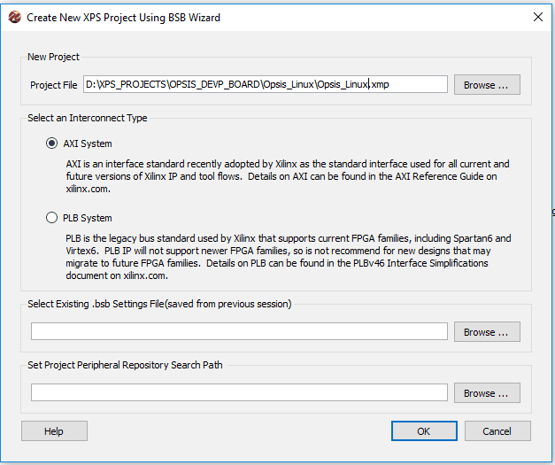
Enter path to a folder where you want to store the project and a project name (Here the project name is Opsis_Linux in the image above). Select AXI System in the interconnect Type section and click OK. In the next page of the wizard, select “Numato Lab” from the Board Vendor combo box (This option should be available if you have placed the BSB wizard support files for Opsis properly as mentioned earlier). Select Opsis and 1.0 from Board Name and Board version combo boxes respectively and click “Next” button to go to the next page:
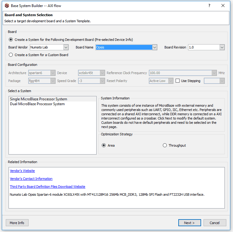
Leave the Optimization Strategy to its default value and click next.
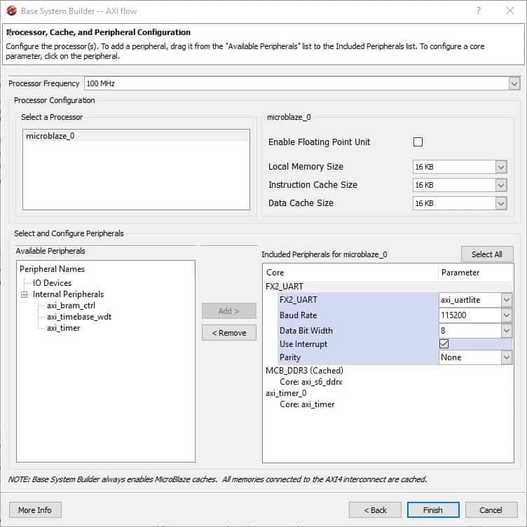
By default, FX2_UART and MCB_DDR3 will be selected. Select memory size, I-cache size and D-cache size as 16KB. Then select FX2_UART peripheral and set the baud rate to 115200 and check the “Use Interrupt” check box. Then select “axi_timer” in the “Available Peripherals” list and add that to the system. Select the timer and check the “Use Interrupt” check box. Make sure everything is setup as shown in the image below and click “Finish” button.
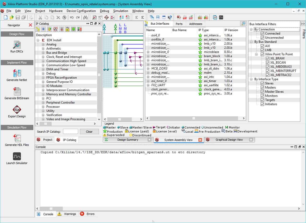
Now Xilinx Platform Studio will generate a project for you based on the selections you made in the BSB wizard. If everything went well, you will be presented with a window as shown below.
There is a bug in XPS where it fails to load valid parameters for MCB_DDR3 from BSB Wizard files. This will result in failure in generating netlist. Workaround for this bug is to just regenerate the files for this IP core. Its not a difficult task. Just double click the “MCB_DDR3” IP and click “Next” at every step and finally click “Finish”. There is no need to modify anything, just leave everything as is and click “Finish”.
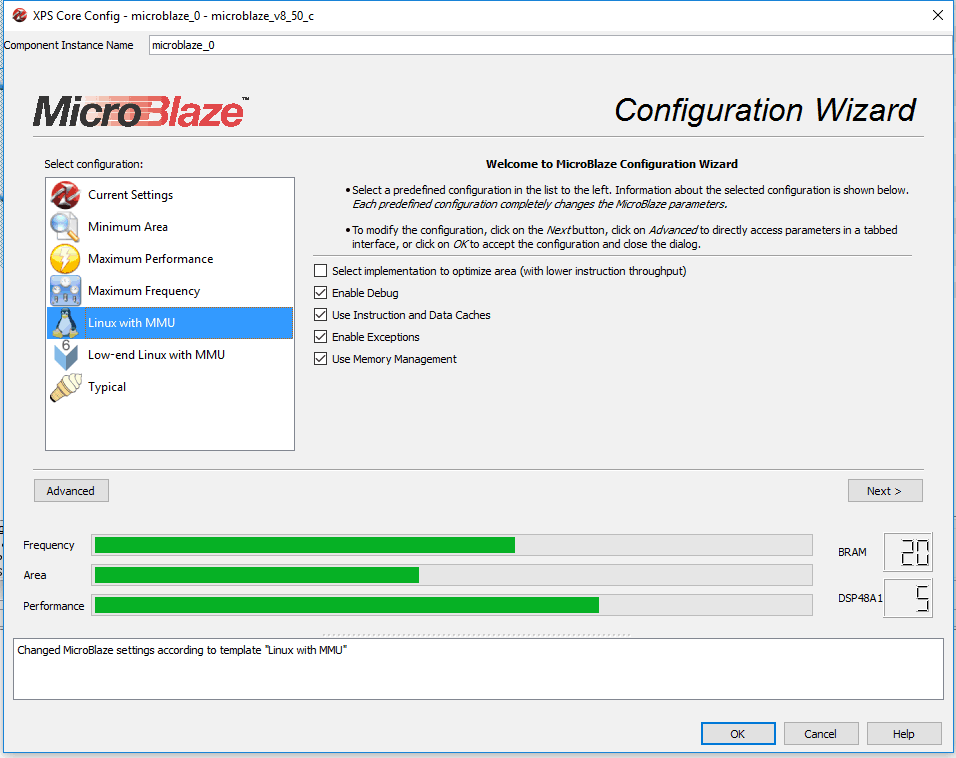
Now we will configure the peripheral IPs. Right click on microblaze_0 in the “System Assembly View > Bus Interfaces” tab and select “Configure IP” from the pop up menu. The Microblaze Configuration Wizard will pop up. Select “Linux with MMU” under the “Select Configuration” options (Please see image below).
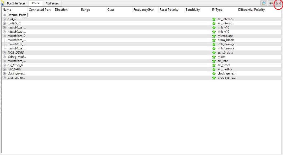
At this point, we have finished configuring Microblaze CPU and all peripherals. The next step is to route all peripheral interrupts to the microblaze CPU through the interrupt controller. To configure interrupts, go to the “Ports” tab in “System Assembly View” and locate the “Open interrupt Control Dialog” button. This button is a little tricky to locate. Please see the image below for help.
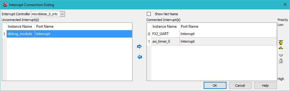
In the interrupt control dialog box, make sure that both FX2_UART and axi_timer_0 are connected to the interrupt controller and debug_module is not connected to the interrupt controller as shown in the image below.
Now go to the “System Assembly View” and select “Addresses” tab and make sure all peripherals have a base address assigned (XPS will take care of this automatically, but just in case). Note the base address of DDR3 memory, we will need it when building Linux kernel. At this point, we are ready to build the project. Click on the “generate bitstream” button the left side pane to start build process. If build fails due to timing closure issues, go to project menu in XPS, select Project Options and uncheck “Treat timing failures as errors”. This should help the build complete without errors.
Now we recommend that you create a SDK application project for this hardware platform and test its basic functionality by creating a “Hello world” application. Please follow the steps similar to the section “Creating Application program for Microblaze based Embedded Platform” in the article Creating Xilinx EDK test project for Saturn – Your first Microblaze processor based embedded design to create a SDK project(creating SDK project for Opsis is similar to creating a SDK project for Saturn). Choose “Hello world” SDK application template when generating the application. Run the application on the board to make sure that everything so far works as expected.
Assuming you were able to build the hardware platform using XPS and test it using SDK successfully, let us move on to the discussion about how to build Linux kernel. There are different ways to do this depending on how much time and effort you would like to invest. The easiest of all is to use a tool such as Buildroot. In this example, we will use Buildroot to build our kernel. Buildroot, when properly configured, can download Linux kernel source, build cross compilation tools and build the kernel itself all with a single command.
Please note that we will continue using Windows for running Xilinx tools (and of course Linux for building kernel). Author has used Ubuntu 14.04 LTS 64 bit desktop version while putting together this article. We will do the following steps one by one to build the Linux Kernel.
Section II: Generating Device Tree
On many platforms, Linux kernel depends on a data structure called Device Tree to discover and configure different hardware components available on the board. Kernel uses the device tree in binary format which is generated by using device tree compiler. The input to the device tree compiler is a text file (with extension .dts) that describes all the hardware and dependencies. This file can be edited manually by hand if necessary. But fortunately, there are tools available that can help us generate device tree from our XPS/SDK projects.
To generate device tree, we will need the following files from XPS/SDK projects.
- Opsis_Linux.xml (can be found under the folder SDK\SDK_Export\hw inside the XPS hardware project. Exact file name may be different depending on the XPS project name you chose)
- system.mss (can be found under the bsp project folder in Hello World SDK workspace)
Copy these two files to a common folder. Open command prompt and move to the folder where the files were copied. Edit the file system.mss and replace the contents of the section that begins with “BEGIN OS” with the following and save.
BEGIN OS
    PARAMETER OS_NAME = device-tree
    PARAMETER OS_VER = 3.10.a
    PARAMETER PROC_INSTANCE = microblaze_0
END
Now download the device-tree.mld and device-tree.tcl files from https://github.com/Xilinx/device-tree/tree/master/data and rename them to device-tree_v2_1_0.mld and device-tree_v2_1_0.tcl respectively. Place these files under the folder bsp\device-tree_v3_10_a\data along with Opsis_Linux.xml and system.mss. Please note that it is critical to use the exact file names and folder names mentioned here. Files should be placed exactly as below.
\Opsis_Linux.xml
\system.mss
\bsp\device-tree_v3_10_a\data\device-tree_v2_1_0.mld
\bsp\device-tree_v3_10_a\data\device-tree_v2_1_0.tcl
Once all files are placed properly, run the following commands at the command prompt.
cmd>c:\Xilinx\14.7\ISE_DS\settings64.bat
cmd>libgen -hw Opsis_Linux.xml -lp device-tree -pe microblaze_0 system.mss
Make sure to replace 14.7 in the first command with the version of ISE you have on your machine. Run settings32.bat instead of settings64.bat if you have 32-bit system.
If everything went well, libgen should run without any errors and a new folder microblaze_0 will be created. You will see xilinx.dts under the folder microblaze_0\libsrc\device-tree_v3_10_a and this is our device tree file. rename xilinx.dts to opsis.dts. At this point, we will need to make some changes to the dts file manually. Open opsis.dts in your favorite text editor and replace the bootargs = “” line with the following
"console=ttyUL1,115200";
linux,stdout-path = &fx2_uart;
stdout-path = &fx2_uart;
Section III: Building Linux Image
Step 1: Login to your Linux workstation to download and setup buildroot. On a Ubuntu 14.04 desktop clean installation you will need to install a few packages to make Buildroot work. Run the following command to install those.
cmd>sudo apt-get install build-essential bison flex gettext libncurses5-dev texinfo autoconf automake libtool
You may need to install Qt lib if you prefer to use xconfig instead of menuconfig while configuring Buildroot (please note that we will not use xconfig or menuconfig in the article rather load a default configuration that is known to be working).
Step 2: Now create a convenient folder on your Linux machine and move to that folder on the command line.The author created “opsis_linux” directory inside his “home” directory. Download buildroot to that folder. You can download buildroot manually from Buildroot download page or by running the following command.
cmd>wget http://buildroot.uclibc.org/downloads/buildroot-2014.05.tar.gz
If you prefer to use a different buildroot release, change the file name accordingly. Extract the downloaded gzip archive by running the following command
cmd>tar -xvf buildroot-2014.05.tar.gz
All files should be extracted to the folder buildroot-2014.05.
Step 3: We need the Linux Kernel defconfig files for Opsis. Download them from here.
1. opsis_defconfig file: place it under the directory “buildroot-2014.05/board/numato/opsis/” You will need to create respective directories named “numato” and “opsis”. Please note the kernel base address is set to 0xa8000000 in the Linux kernel defconfig file. Please change it appropriately if the DDR3 base address is different in your XPS project. Now copy the “opsis.dts” to the same folder as well.
2. Now, buildroot defconfig file “numato_opsis_defconfig” : copy it to the “configs” folder inside buildroot root directory (ie. “buildroot-2014.05/” )
After setting up buildroot as mentioned above, execute the following commands at the Buildroot root directory.
cmd>make numato_opsis_defconfig
cmd>make
The first make command will generate a .config file for Buildroot and the second make command will build the kernel. Please note that the machine should be connected to internet for this step to work since Buildroot needs to download Linux kernel sources and other tools before it can begin building the kernel. This step can take up to an hour or more depending on your machine’s speed and internet connection speed.
Upon completion, this step creates a “simpleImage.opsis” Linux image in the directory “buildroot-2014.05/output/images/”. This is the Linux kernel with a root file system (initramfs) attached to it. We will use this file to boot Linux on Opsis.
Section IV: Running Linux on Opsis
Preparation:
Before we can run anything, we need to configure drivers for Opsis and download proper firmware on its Cypress FX2 chip, so that we can interface with its UART interface. Let’s do that first.
Step 1: Download and install Cypress FX2/FX3 toolchain from Cypress website. This toolchain is necessary because it contains generic Cypress drivers and also utilities for programming Cypress chips. Please refer to Cypress website on how to download and install Cypress toolchain.
Step 2: Once the Cypress toolchain is installed, change the jumper K3 on Opsis (near USB Type-B connector) from 2-3 to 1-2.
Step 3: Power on Opsis and connect to host PC.
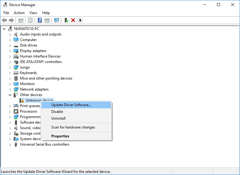
Step 4: Open Device Manager on Windows. It will show Opsis as “Unknown device”. Right click and select “Update Driver Software…”
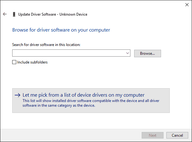
Step 5: In the next window, select “Browse my computer for driver software”
Step 6: In the next window, select “Let me pick from a list of device drivers on my computer”
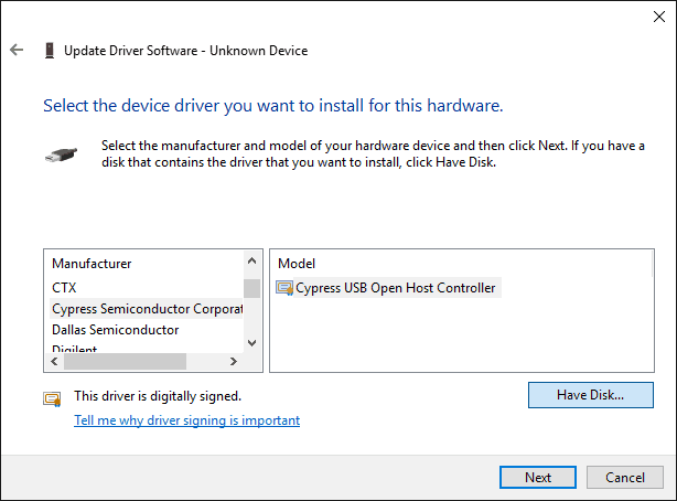
Step 7: In the next window, scroll down to Manufacturer “Cypress”. If there is no “Cypress” and instead only “Cypress Semiconductor Corporation”, select “Have Disk…” button.
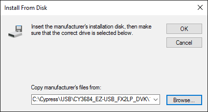
Step 8: Browse to the location where the toolchain installer extracted the drivers. In author’s case it was “C:\Cypress\USB\CY3684_EZ-USB_FX2LP_DVK\1.1\Drivers” but it might be different in your case. Choose appropriate location applicable in your case. Select “OK”.
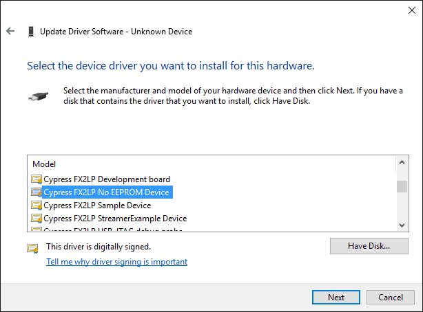
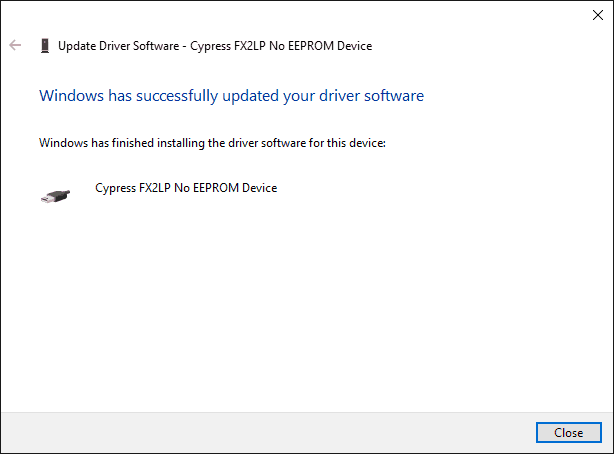
Step 9: In the next window, select “Cypress FX2LP No EEPROM Device” and click “Next”. Select “Yes” to any warnings. Drivers should now be successfully installed.
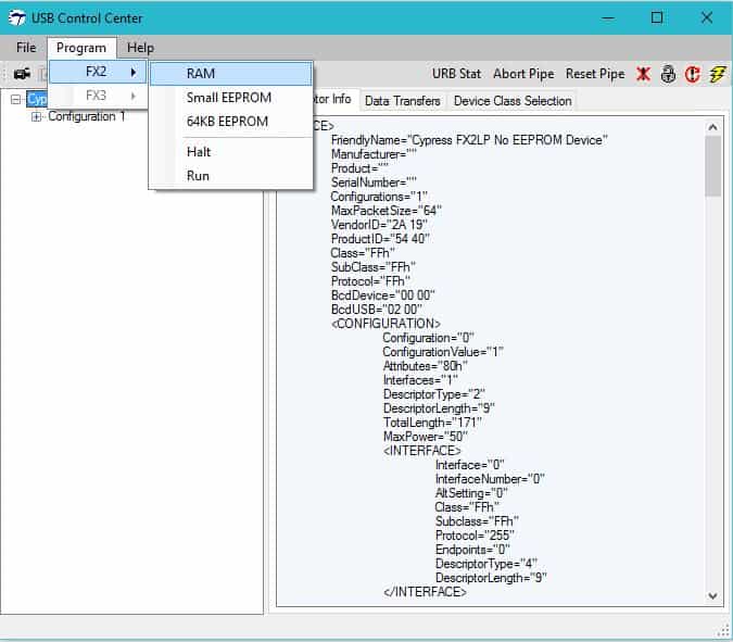
Step 10: Now, open Control Centre utility application which comes with Cypress toolchain. Select “Program” -> “FX2” -> “RAM”
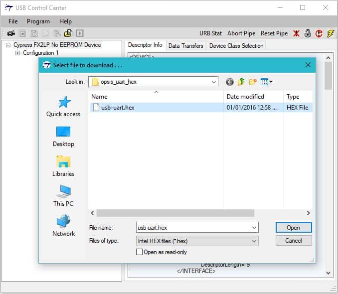
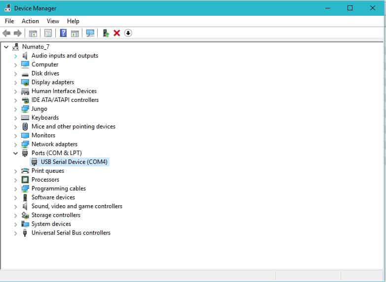
Step 11: Open the file “usb-uart.hex” downloaded from here. The Fx2 will now be programmed with usb-uart firmware, and should now show up in Device Manager as a USB Serial Device with an associated COM port.
We can now proceed with running Linux on Opsis.
Running Linux:
Step 1: Connect the Xilinx Platform Cable to the Opsis board and power it up. Open any Serial terminal program (Putty, TeraTerm etc) and connect to Opsis at 115200 baudrate. First run the Hello World program and memory tests again to make sure everything is connected properly and works.
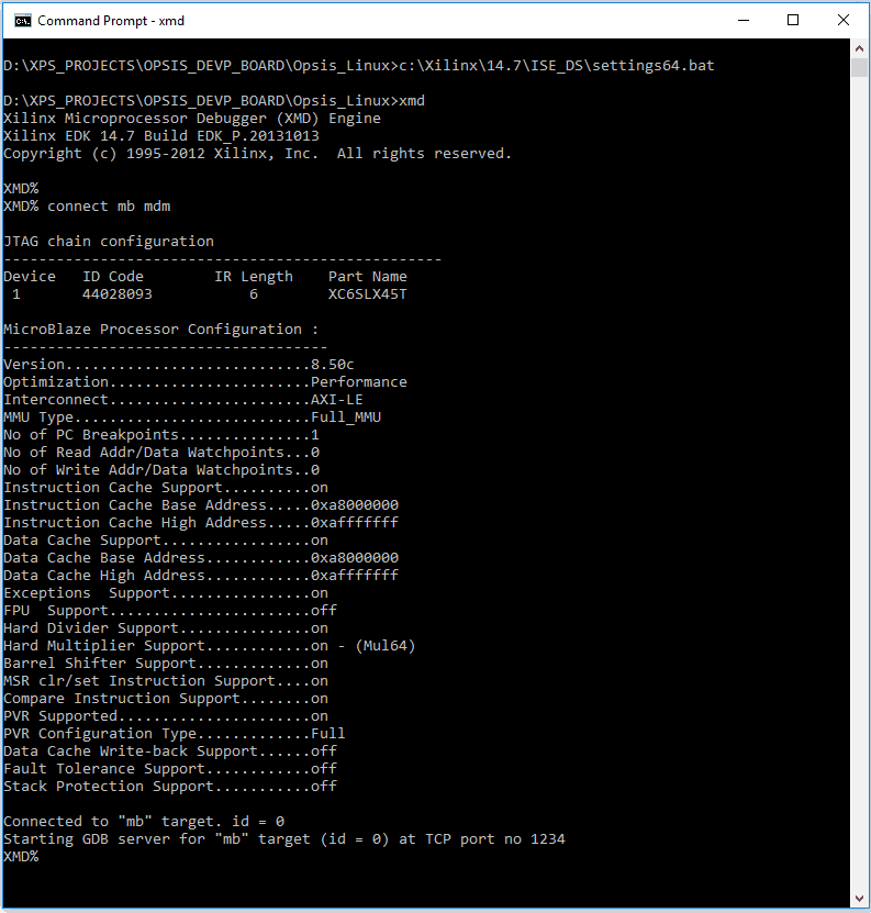
Step 2: Once FPGA programming is finished, we can now communicate with the Microblaze processor through XMD. It is possible to invoke XMD within SDK but I found it very easy and convenient to invoke XMD in a standalone commandline (DOS) window. Before starting XMD, copy “simpleImage.opsis” in the folder /output/images under buildroot directory on Linux build machine to the Windows machine. Open a new commandline window (in Windows) where the kernel image is copied and run the following commands.
cmd>c:\Xilinx\14.7\ISE_DS\settings64.bat
cmd>xmd
Make sure to replace xx.xx with your ISE version and to choose settings32.bat if your system is 32 bit. These commands will start XMD within the commandline window. Now type the following command at the XMD command line to connect to the Microblaze processor running on the FPGA.
cmd>connect mb mdm
If everything went well, you should see XMD spit out some information as shown below.
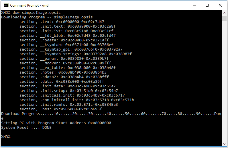
Step 3: Now we are connected to the Microblaze processor and we can download Linux kernel image. To download the image, run the below command at XMD command line.
dow simpleImage.opsis
This command should start downloading the image to the DDR memory. Since simpleImage.opsis is in ELF format, it already contains the DDR address where it should be copied to. If download fails, chances are that you have not updated the Linux kernel base address with the starting address of the DDR3 memory assigned by EDK before building Linux kernel. It can take a few minutes to download the kernel image to DDR. Below image shows the download process.
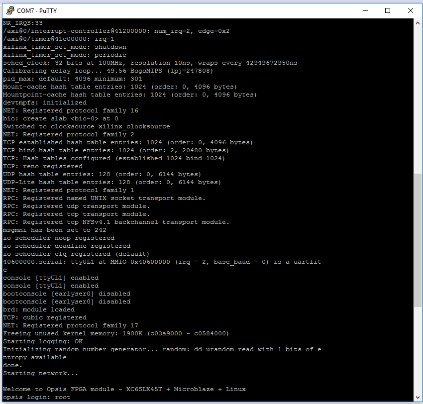
Step 4: Now we are ready to boot Linux. Open your favourite serial terminal emulation software (hyperterminal, PUTTY, Teraterm etcc..) and open the serial port corresponding to Opsis’s UART. Set baud rate to 115200 and set any handshacking to off/none. Once the terminal software is setup, run the following command at XMD commandline to boot the kernel.
cmd>con 0xa8000000
Make sure to replace 0xa8000000 with the DDR base address/Kernel base address of your system if it is different. If all steps so far went as planned, you should see Linux booting in the serial terminal software as shown below.
The default user is root and no password set for root user. Image below shows root directory structure, cpuinfo and “uname -a” output: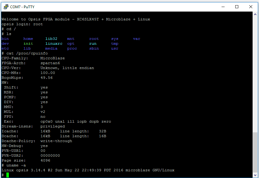
Congratulations if you followed the steps in this article series and were able to boot Linux successfully. Those who could not successfully boot, please don’t give up and keep trying. You should be able to tackle this without much difficulties.