Introduction
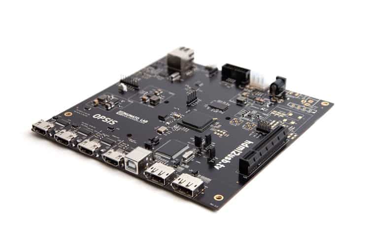
HDMI2USB is a firmware project that can run for Numato Opsis FPGA based open video platform. This firmware enables Opsis to capture or generate HDMI, DVI or DisplayPort (future) video. The captured video can be transferred to host PC through the USB interface available. With HDMI2USB firmware programmed, Opsis shows up on the host PC as a standard webcam, so no additional drivers required on Linux to use the basic functionality. But, Windows needs a driver to be installed. Please refer to this article on how to install driver for HDMI2USB on Windows. This article will discuss how to program and use HDMI2USB firmware on Numato Opsis FPGA based video platform. HDMI2USB is capable of capturing HDMI streams from 2 sources and routing them to 3 possible locations, ie; USB or the 2 HDMI output ports present on Opsis. Currently though, HDMI2USB doesn’t support DisplayPort capture. It is a work that is still in progress.

HDMI2USB Opsis Application. Image copyright: Katie McLaughlin @glanst, CC-BY-SA
Prerequisites
To follow this article, you will need:
- Hardware:
- Numato Opsis Board
- USB 2.0 B-type cable
- DC power Supply(12V)
- 2x HDMI Cables (exact number depends on your application)
- A separate monitor with HDMI input
- An HDMI Source (Laptop/PC/Raspberry Pi etc)
- Software:
- Windows OS, preferably Windows 10
- USB Webcam viewer (Windows 10 ships with “Camera” application)
Connections:
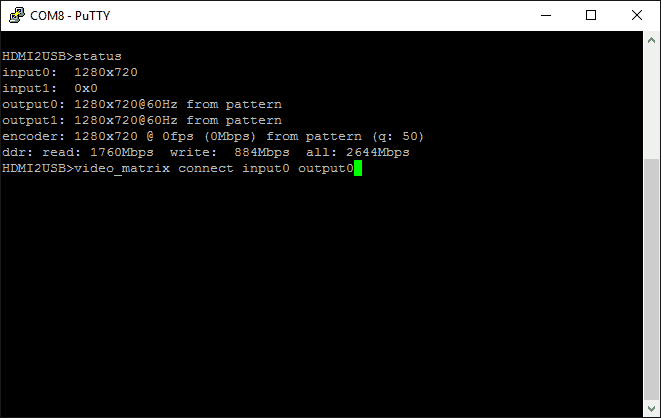
For this article, we will use a configuration as shown below. HDMI2USB on Opsis can handle more complex configurations but we will use a simple configuration now.
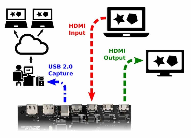
HDMI2USB Opsis Connections. Image copyright: Katie McLaughlin @glanst, CC-BY-SA
- Connect an HDMI source to HDMI IN 1 of Opsis
- Connect an HDMI cable from HDMI OUT 1 of Opsis to monitor
Here HDMI source refers to devices capable of generating HDMI signal such as laptop, desktop, Raspberry Pi, another Opsis etc. And sink refers to devices capable of receiving HDMI signals such as monitors, yet another Opsis etc.
In the author’s case, the host PC was connected to a monitor using VGA interface. So, that left a spare HDMI output on the same PC which was connected to HDMI IN 1 on Opsis.
HDMI OUT 1 of Opsis was connected to another monitor. A USB cable was connected from host PC to Opsis. And finally Opsis was powered up using a 12V external power supply.
Getting started:
As soon as Opsis is powered up, the monitor connected to HDMI OUT 1 will start showing a color bar pattern (unless the factory-programmed with HDMI2USB firmware is altered in some way).
Note: Drivers should be correctly installed for the steps listed below to work. Please refer this article on how to install HDMI2USB drivers on Windows for Numato Opsis board.
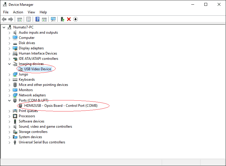
Step 1: If the drivers are properly installed, HDMI2USB on Opsis will show up as 2 different devices in the Device Manager as in image below. The first device would be a standard USB Webcam and second one a serial COM port for interacting with HDMI2USB firmware.
Step 2: Connect to the control port using a serial terminal software. We will use PuTTY in our case, but any serial terminal program should work just fine. Enter the serial port name corresponding to HDMI2USB and set the baud-rate to 115200 as shown below:
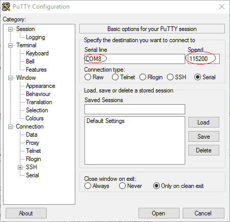
Now, before clicking “Open” button, go to “Terminal” tab and check “Implicit CR in every LF” and “Implicit LF in every CR”.
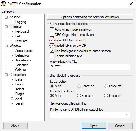
We can now open the port by clicking the “Open” button.
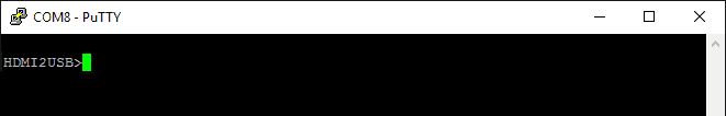
Step 3: If everything went well, we will see a blank PuTTY screen. Press ENTER key to get the HDMI2USB prompt as shown in the image below:
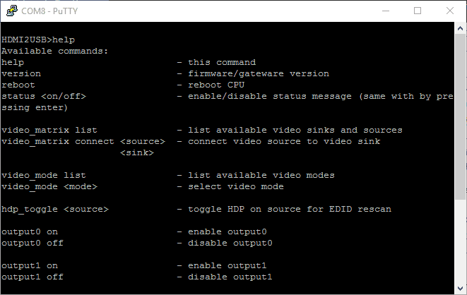
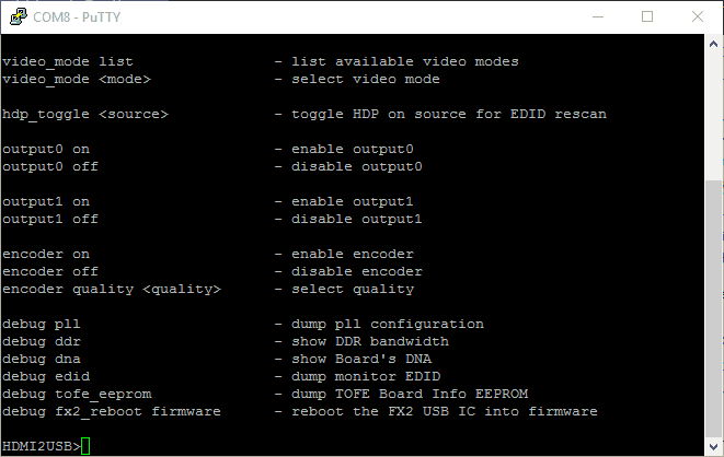
Step 4: Type “help” and press Enter to see a list of supported commands. With the help of these commands, we can control and debug HDMI2USB.
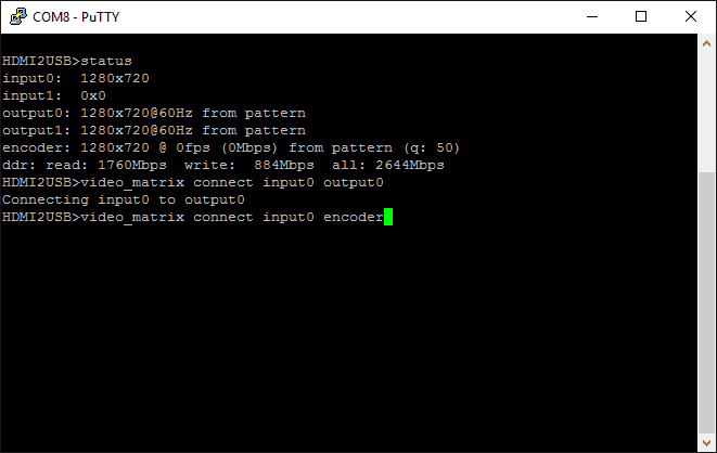
Step 5: Enter “status” command on the serial terminal to display the status of HDMI2USB firmware as shown in the picture below:
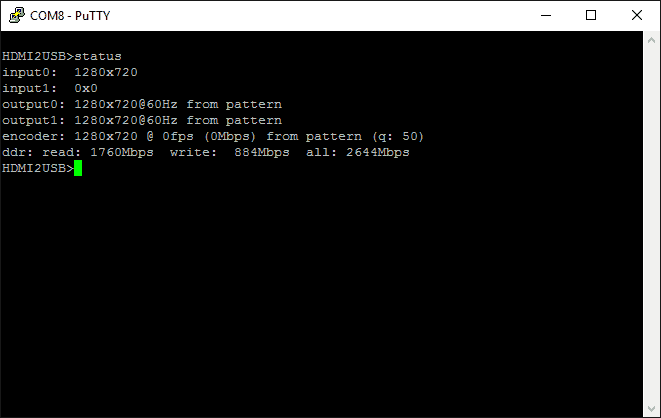
As we can see in the picture above, input0 is being correctly detected (This input is connected to HDMI source). Since we didn’t connect anything to input1, no input signal is detected as expected. Also, output0 andoutput1 are enabled and showing “pattern” (This means signal for these outputs are generated from a built in pattern generator ). Encoder is also enabled but no host program is currently streaming video through USB hence 0Mbps data rate shown.
Step 6: Now we can connect input(source) to output(sink) by using the following command:
video_matrix connect <source> <sink>
source can be: input0, input1 or pattern
sink can be: output0, output1 or encoder
The illustration below will make this much clearer:
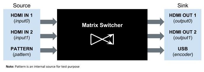
So, lets connect input0 to output0.
video_matrix connect input0 output0
This command will cause output0 (ie HDMI OUT 1) to display whatever the Opsis board is receiving at input0(HDMI IN 1). And in our case, signal at input0 (HDMI IN 1) is coming from host PC’s HDMI output. Windows on host PC will detect Opsis as another display and it will automatically set the resolution, by default, to 1280×720. We can clone the existing display or extend the display. In our case, Windows has been set up to extend the display.
So, we will now get the extended Windows Desktop on the monitor which was connected to HDMI OUT 1
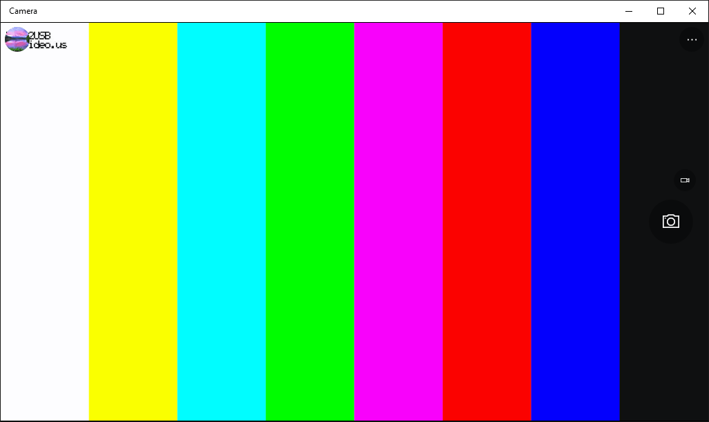
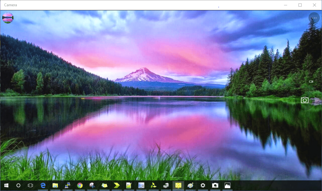
Step 7: To view the stream through USB interface, we will need to install appropriate software. Windows 10 already comes pre-installed with “Camera” application which can used to view video stream from webcams. If we open the “Camera” application 10, we will see the default pattern as below. This is because the encoder is still connected to pattern generator. We will need to connect input0 to the encoder so we can stream the video from input0 through USB.
So, lets try connecting encoder to input0 so that we can view our extended desktop back into our PC.
video_matrix connect input0 encoder
Now we will get a nice live capture of our extended desktop on host PC’s display (as shown in screenshot below) :
Conclusion
This was just basic introduction on how to use HDMI2USB firmware with Numato Opsis. HDMI2USB is capable of doing much more and the continuous development is expected to bring even more features to the table. This article demonstrates how easy it is to setup and use HDMI2USB firmware with Numato Opsis FPGA based video platform.