Introduction
FPGAs are best known their flexibility and versatility. Such flexibility allows FPGAs not only be used for custom logic circuits but also implement a processor on it and even run Linux (or other operating system)on the processor. The possibilities are only limited by imagination, also by FPGA speed grade and size. This article will discuss how to create/implement Microblaze processor and run Linux on Neso Artix 7 FPGA Module. This series is based on our article series for Spartan 6 FPGA Module. So we highly recommend that you read the series for Saturn and get yourself familiar with the steps. So let’s dive right in.
Structure
This article is structured into 4 sections.
- Section I: Creating the Microblaze based design for Neso
- Section II: Generating Device Tree
- Section III: Building Linux Image
- Section IV: Running Linux on Neso
Prerequisites:
For following this article, you would need these:
- Hardware:
- Neso Artix 7 FPGA Module
- Xilinx Platform Cable JTAG debugger
- Software:
- Xilinx Vivado installed on either Windows or Linux system
- Linux system (author used Ubuntu 20.04 64-bit on a Virtual Machine)
- Good internet connectivity
Creating the Microblaze based design for Neso
Creating a Microblaze based design for Neso is very straight forward. Detailed steps for creating a Microblaze design is available in this article. Please read through this article and follow the steps to create a vanilla Microblaze based design and make sure the Memory Test program runs and passes all tests.
We will be modifying the design created above to run our Linux system. Open the block design created above, and double click on the Microblaze block. We need to modify this IP block to be able to run Linux on our board.
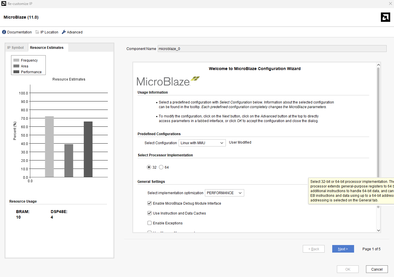
Choose “Linux with MMU” configuration as shown in the image above.
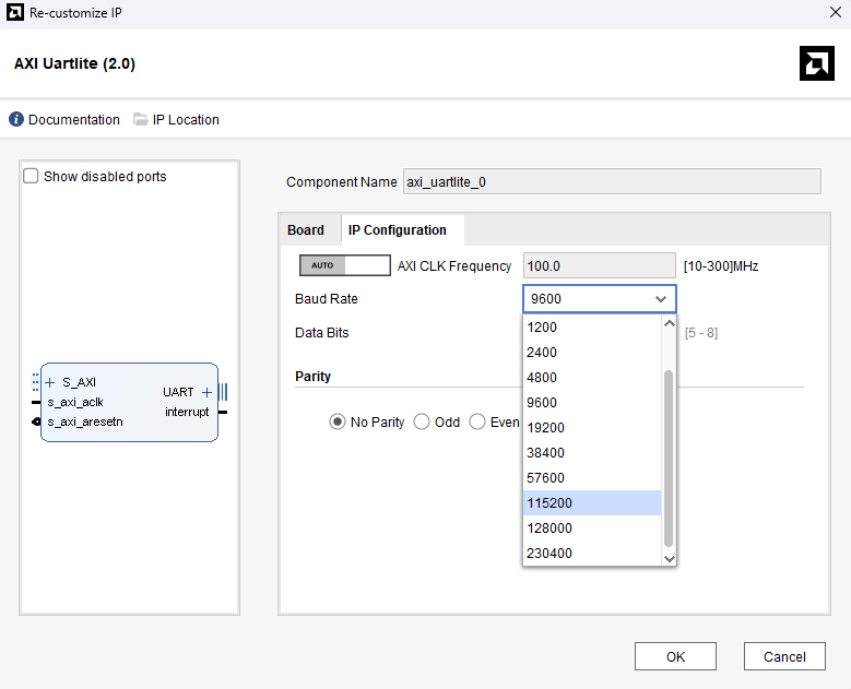
We also have to increase the baud rate of UART. Double click on “uartlite” IP and change its baud rate to 115200.
Now, we are ready to build our Linux capable design. Click “Generate Bitstream” and click “Yes” when it asks for running Synthesis and Implementation before that. Once the bitstream is successfully generated, export the hardware along with bitstream. We will launch Vitis later in next section.
Generating Device Tree
On many platforms, the Linux kernel depends on a data structure called Device Tree to discover and configure different hardware components available on the board. The kernel uses the device tree in binary format which is generated by using the device tree compiler. The input to the device tree compiler is a text file (with extension .dts) that describes all the hardware and dependencies. This file can be edited manually if necessary. But fortunately, there are tools available that can help us generate a device tree from our Vivado/Vitis projects.
Having completed all the steps before, now download the device-tree repository from Xilinx’s GitHub account: https://github.com/Xilinx/device-tree-xlnx. If you downloaded the zip file, extract it in the same location as your Vitis workspace. The author extracted it to “C:\Projects\Neso_A7\Hello_world\Linux_Vitis\device-tree-xlnx-master” directory. To generate a Device tree follow the steps below.
Step 1: Launch Vitis Classic.
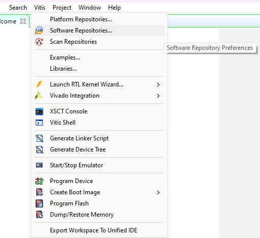
Step 2: In Vitis , go to “Vitis” and click “Software Repositories”.
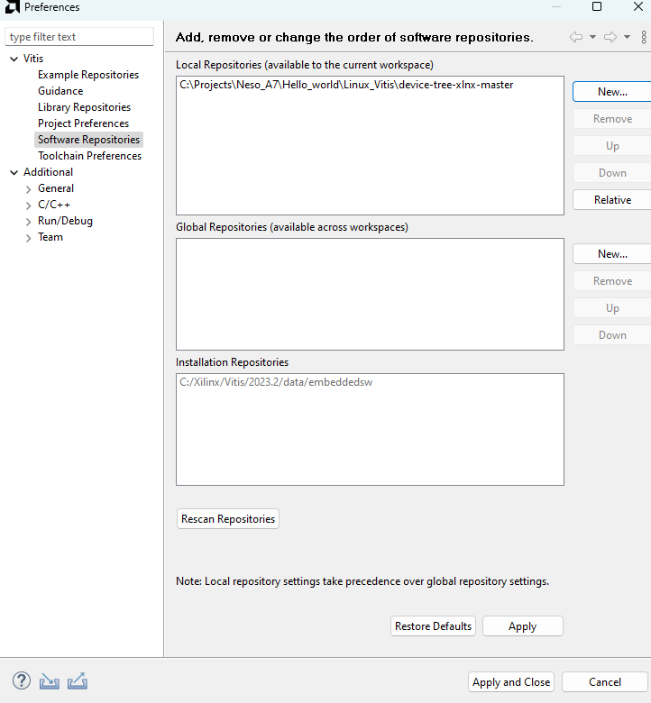
Step 3: In the dialog window, select “New” and select the device tree folder which you had downloaded and extracted to Vitis workspace in the “Local Repositories” section. Click “OK”.
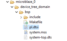
Step 4: Click on “Create Platform Project“. In the “Create a new platform from hardware (XSA)” browse and select your XSA file. Select the “Operating system” as “device_tree” and click on “Finish“. This should generate a system.dts file along with a .dtsi file. We need both of them.
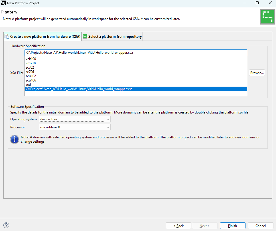
This should generate a system.dts file along with a .dtsi file. We need both of them.
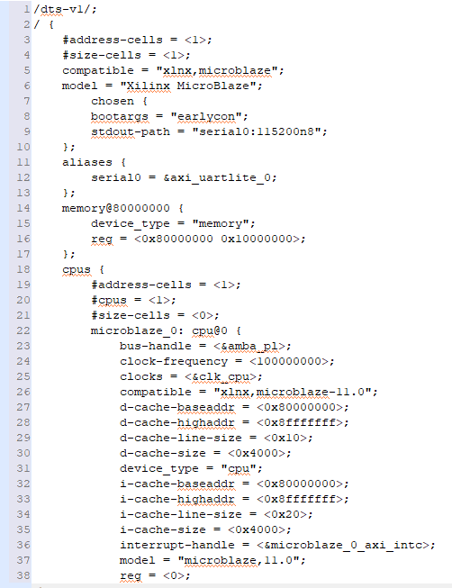
Step 5: We have to merge the ‘.dtsi’ and ‘.dts’ files. So open both of them in some text editor (Notepad++ etc) and copy the contents of system.dts and paste them in the .dtsi file just after the line ” model = “Xilinx MicroBlaze” . Don’t forget to add “/dts-v1/;” at the top of .dtsi file also. The final content should look like this:
Now, save this modified file as “nesoartix7.dts”. And copy “nesoartix7.dts” file to your Linux System.
Section 3: Building Linux Image
Now we need a Linux system to build Linux Image. In this article, the author used Ubuntu 20.04 64-bit for building a Linux image.
Follow the steps shown below to Build a Linux image:
Step 1: After a clean installation of Ubuntu 20.04.6, you will need a few packages to make Buildroot work. Run the following command in the Linux terminal to install those:
sudo apt-get install build-essen flex gettext libncurses5-dev texinfo autoconf automake libtoolntial biso
Step 2: Create a convenient folder on your Linux system and ‘cd’ to that folder. The author created a directory with the name “NESOA7_LINUX” in his “home” directory. Now download “buildroot” to the created directory, either manually or by using the following command:
wget http://buildroot.uclibc.org/downloads/buildroot-2018.11.tar.gz
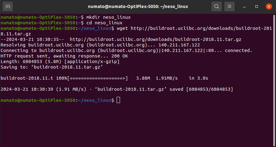
You can use latest buildroot release instead of the above. Now, extract the downloaded tarball archive using following command:
tar -xvf buildroot-2018.11.tar.gz
All files should be extracted to the folder “buildroot-2018.11”
Step 3: We need the Linux Kernel defconfig files for Neso. Please get them from here: https://github.com/numato/samplecode/tree/master/FPGA/neso/nesoLinux-BSP
neso_defconfig file: place it under the directory “buildroot-2018.11/board/numato/neso/” You will need to create respective directories named “numato” and “neso”. Please note the kernel base address is set to 0x80000000 in the Linux kernel defconfig file. Please change it appropriately if the DDR3 base address is different in your Vivado project.
Now copy the “nesoartix7.dts” to the same folder as well.
Now, buildroot defconfig file “numato_neso_defconfig” : copy it to the “configs” folder inside buildroot root directory (ie. “buildroot-2018.11/” ).
After setting up buildroot as mentioned above, execute the following commands at the buildroot root directory:
make numato_neso_defconfig
This will create a .config file for buildroot. Next, execute the below command:
make
Before executing the above command, please make sure that Python and OpenSSL header files should be installed in the Ubuntu system. If these files are not installed in your system execute the following commands to install.
To install python files run the following command:
sudo apt install python
To install OpenSSL header files execute the below command:
sudo apt install libssl-dev
After successful completion of the installation of those files, execute the “make” command. This command will build the kernel and its file system. This downloads the kernel sources and lots of other tools from the internet. It will take some time to finish building the kernel image, from 30 minutes to over an hour, or even more, depending on your machine’s capabilities and your internet speed.
Upon completion, this step creates a “simpleImage.nesoartix7” linux image in the directory “buildroot-2018.11/output/images/”. This is the Linux kernel with a root file system (initramfs) attached to it. We will use this file to boot Linux on Neso Artix7 FPGA Module.
Section 4: Running Linux on Neso
Step 1: Copy the Linux image and place it in a convenient directory and open Vitis. Connect the Xilinx Platform Cable to the Neso FPGA Module and power it up. Make sure the FT2232’s channel B is configured for RS232. Open any Serial terminal program (Putty, TeraTerm etc) and connect to Neso at 115200 baudrate.
Step 2: First run the Hello World program again to make sure everything is connected properly and works. Now, go to Vitis -> XSCT Console, type in a command “target” it will show all the targets connected, note down the number where MicroBlaze 0 is connected (3 in this article), connect to MicroBlaze by giving the command:
target 3
Now, ‘cd’ to the directory where your kernel image is located (..\\images). Download the kernel image by using the following command:
dow -data simpleImage.nesoartix7 0x80000000
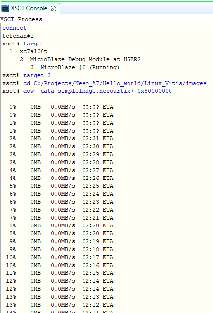
Wait for download to complete. If the image is successfully downloaded, continue the processor from DDR3’s address. In author’s case it was:
con 0x80000000
If all the steps so far went as planned, you should see Linux booting in the serial terminal as shown below:
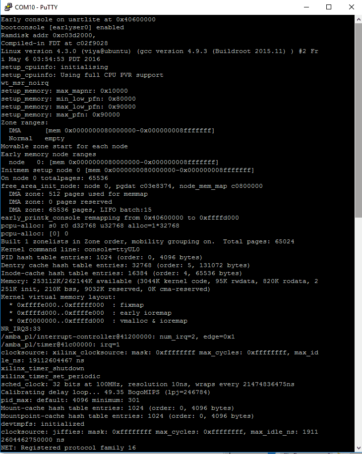
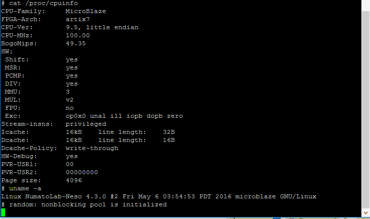
You can login to Linux with username “root” and password as “neso”. Now we have a successfully running Linux kernel in Neso Artix 7 FPGA Board! Congratulations! In the next article we will see how to flash kernel image to the onboard SPI Flash on Neso!