For many of us, learning FPGA was a natural next step from the world of micro-controllers and Embedded System. You learn the basics of Embedded System, do some projects using micro-controllers and microprocessors and one day realize that those devices may not be the best choice for a particular problem that you want to solve. A little research could lead you to FPGAs. But the FPGA world is very different from the micro-controller world you have seen so far. While micro-controller and Embedded System experience is very helpful, it can not help you get started with FPGAs without a somewhat steep learning curve. The tools are different, languages are different and even the programming paradigm is different.
But there is hope. By definition (in loose terms) FPGA is a bunch of logic elements that can be configured to make any logical circuit. If that is true, why not make a microprocessor out of those logic cells and program using traditional Embedded System friendly languages and tools? Yes, it is possible. But there is a question as to why this method of making a micro-processor or micro-controller out of FPGA logic is better compared to off the shelf micro-processors? There are many reasons why making microprocessor/controller in FPGA fabric is better (or worse) compared to an off-the-shelf micro. The most important reason is that you have access to the FPGA fabric from the micro-controller (through buses and peripherals created within the fabric, of course) and you can implement peripherals from a vast array of Xilinx’s freely available peripheral IPs or create your IP (or buy third-party IPs). It is possible to make pretty much any peripheral that you want within the capability of the FPGA that you have chosen to work with. There are a few important downsides to this scheme though. The total cost of hardware will be usually higher compared to an off-the-shelf micro for the same amount of raw processing power. If you can not find the peripheral IP that you are looking for, you will end up having to write one using Verilog or VHDL and you are back to square one (remember, what we wanted to do was not to deal with HDLs or FPGA workflow at all). It is possible to buy third-party IPs but depending on the specific IP, it can be very expensive. Also, it is worth mentioning that the tools required to build an embedded system out of an FPGA could set you back by a few hundred dollars.
Let us take a look at what a processor-based embedded system built into an FPGA would look like in it’s simplest form. As you can see in the diagram below, an embedded system built in FPGA fabric is not really different from any other embedded system. It has a processor, memory, buses, and peripherals etc. everything that you would expect in a normal Embedded System configuration. It is just that the processor, buses, and peripherals are all made by using logic cells that are available within the FPGA.
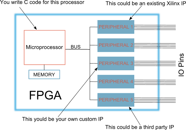
As you can see here, you could use a variety of peripherals from a variety of sources. The peripherals could be communication peripherals such as I2C, SPI, USART or signal processing cores such as FFT, filters or anything that you could imagine and implement on the FPGA fabric. This flexibility gives FPGA based embedded systems an edge in some situations compared to traditional microcontrollers where peripheral choices are often less flexible.
Embedded Infrastructure by Xilinx
Xilinx is arguably the world leader in FPGA and other programmable logic. They provide tools for building embedded systems around many of their FPGAs. Xilinx offers two kinds of fundamental options when it comes to implementing an Embedded System.
- Processor instantiated on FPGA fabric or so-called Soft Processors (Microblaze, Picoblaze)
- Hard processor on the die which has dedicated connectivity to FPGA fabric
As you can imagine, soft processors will use part of FPGA fabric to function and you have to be happy with what is left in order to implement your own peripherals. But with Hard processor cores, FPGA fabric is not used for implementing the processor and you will have 100% of FPGA fabric (or close to 100%) to implement your own peripherals. Hard processor cores are usually more powerful as well. But as of writing this article, the price of FPGAs with built-in hard processor cores tend to be higher.
During this tutorial we will stick with Soft processors, Microblaze to be specific. This is because Microblaze can be implemented on relatively inexpensive hardware such as Mimas V2. Please note that Microblaze soft processor is not compatible Spartan 3 devices. So the information in this tutorial (Part 5) is not applicable to Elbert V2 FPGA Development Board.
In simple terms developing an Embedded System with Xilinx FPGAs consists of the following steps.
- Create a Microblaze based embedded system project
- Add additional peripherals as necessary
- Configure the processor and other subsystems
- Build the processor core and all subsystems to generate a bit file that can be programmed to FPGA
- Create a software project that can run on the hardware ware infrastructure already made
- Write your own program in C and build
- Download everything to the FPGA and run
While it sounds a little complicated, Xilinx’s powerful tools make it very easy to implement those steps in practice. In fact, we will implement a working Embedded System with writing less than 10 lines of code. Now it looks like it is the right time to introduce Xilinx’s tools that we will use to accomplish the above steps. We will be using the following tools throughout the rest of this tutorial.
- Xilinx ISE Webpack 14.7 (http://www.xilinx.com/products/design-tools/ise-design-suite/ise-webpack.html)
- Xilinx Platform Studio
- Xilinx SDK
ISE is the primary FPGA design tool offered by Xilinx. This software includes an IDE and associated tools to implement HDL and realize it in hardware. Please see the previous parts of this tutorial to see some examples of how to create and build projects with ISE. Though it is important to have ISE installed on your system for Platform Studio and SDK to work, we will not be using the ISE IDE in this tutorial.
Xilinx Platform Studio and SDK together often called EDK (Embedded Development Kit). Xilinx Platform Studio is the tool you will use to design the hardware part of the embedded system (Processor, peripherals, buses etc..). Xilinx SDK is a software development environment based on Eclipse IDE. A lot of people will find the SDK tool visually very familiar because of this. Using SDK, you can create software projects and write C code that would run on the Embedded System designed using Platform Studio. Confused? don’t worry, everything will become much clearer when we go through the process step by step.
Xilinx ISE, platform Studio, and SDK can be downloaded and installed from Xilinx website as a single package. But they are licensed separately. You will need one license for ISE Webpack (unlimited license but device limited, good enough for these tutorials) and another license for EDK (Can be purchased here. Xilinx used to offer 30-day evaluation license. Please contact Xilinx to find out more information). How to download, install and license these tools is beyond the scope of this tutorial. Please visit xilinx.com to get more help on this.
Let’s get our hands dirty
To keep this tutorial concise and easy to follow, we will implement a simple Hello World Embedded System. Once implemented, it will print “Hello World” through the serial port. We will use the Mimas V2 FPGA Development Board as the hardware platform to implement this project. Mimas V2 has a Spartan 6 LX9 FPGA and an onboard USB – Serial converter which would help us print data to the PC.
Step 1, Configuring and Building Microblaze Soft Processor and Peripherals
So far we have looked at some basics and selected a hardware platform. Now we will create a project using Xilinx Platform Studio and configure Microblaze based soft processor and some peripherals. Before we can create a project we must copy some supporting files to the EDK installation directory. These files will help us create and configure the project with a few simple mouse clicks. Download the Base System Builder Wizard for Mimas V2 and extract the contents to the “board” directory within Xilinx EDK installation. If you have installed ISE/EDK 14.7 on C:\ drive, the whole path to these files will be C:\Xilinx\14.7\ISE_DS\EDK\board\NumatoLab\ipxact\MimasV2\data .
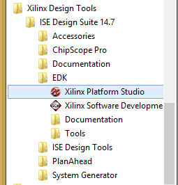
Now launch Xilinx Platform Studio from the start menu.
After Platform Studio GUI is loaded, click on File > New BSB Project. In the project Wizard window that shows up, enter a path and name for the new project. In the image below, “C:\embedded\HelloWorld\edk” is the path and “HelloWorld” is the project name.
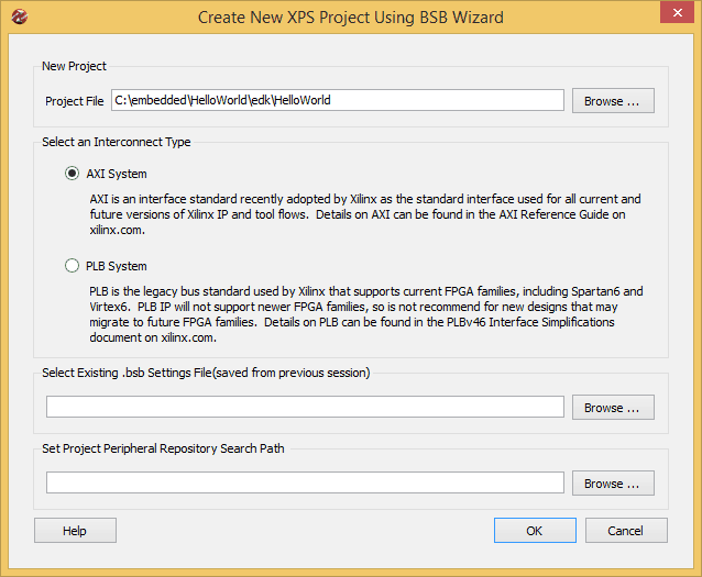
Click OK to continue. In the next window, select Nuamto Lab Mimas V2 as the development board. Leave all other settings to default. Refer to the image below for sample settings.
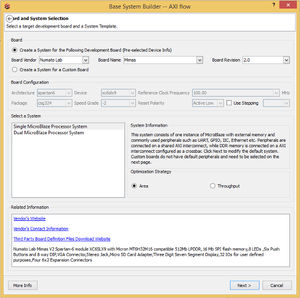
Click “Next” to continue. In the next Window, make sure that only UART is selected as peripheral as shown in the image below. Leave all other settings to default.
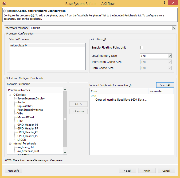
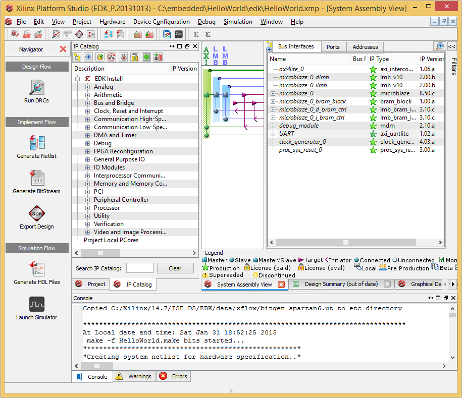
Click “Finish” to finish the wizard and generate the project. If everything went well, you will be presented with a window similar to the image below.
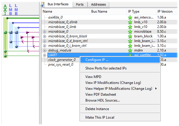
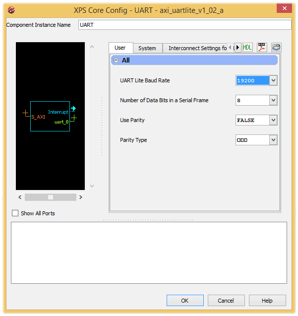
All IPs that are included in the project are configurable to suit your needs. But the only change that we need to make here to get this demo working is the UART Baud Rate. Right click on the UART IP and select “Configure IP” from the popup menu. In the IP configuration window, select 19200 baud rate and click OK. The images below show these steps.
One more change that we need to make to the project is changing the startup clock. By default, XPS will set JTAG clock as FPGA startup clock. This is perfectly fine when we are using a JTAG adapter such as Xilinx Platform Cable – USB for programming FPGA. But to load FPGA configuration from SPI flash, we need to set startup clock to Cclk instead of JTAGCLK. To do this, go to the “Project” tab right next to the “IP Catalog” tab in XPS and open the Bitgen Options file “etc/bitgen.ut”. Change the line “-g StartUpClk:JTAGCLK” to “-g StartUpClk:CCLK”. Save the file and rebuild the project by clicking the “Generate bit file ” button on the left pane. It can take a few minutes for XPS to build the project. Once the build is completed successfully, you will see a message “Bitstream generation is complete. Done!”. If errors popup (ideally shouldn’t), fix them and rebuild. We are done with creating our embedded system hardware, it is that easy!
Now we can export the output files and create an SDK project. SDK is the tool that we will use to create a build application that will run on the Microblaze microprocessor. Click on the “Export Design” button in the left side toolbox in XPS. In the window that pops up, click “Export Only”. XPS will export all files necessary for creating an SDK project.
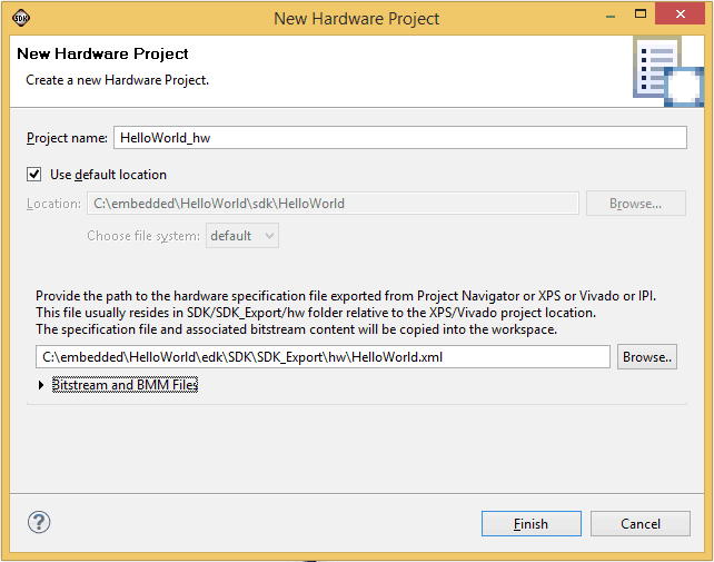
Now launch SDK by selecting “Xilinx Software Development Kit” from the start menu. Select a convenient folder as a workspace and click OK. To create a new project, click File > New Project > Application Project. The application Project Wizard will pop up and ask you to enter a project name a project name. We will call this project “HelloWorld”. In the same window, under “Target Hardware” section, click on “hardware Platform” Combo box and select “Create New”. The “New Hardware Project” wizard that pops up. Fill in a project name and click on the “Browse” button and navigate to our XPS project and find the folder SDK and select HelloWorld.xml (full path is SDK\SDK_Export\hw\HelloWorld.xml). Then click Finish. Please see the image below for an example.
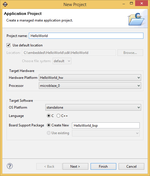
Once a new hardware platform project is created, you will be sent back to the SDK Application project wizard. The newly created hardware platform will be selected in the application wizard automatically. The wizard should like as in the image below when everything is set-up properly.
Click “next” and select “Hellow World” project template and then click “Finish”. Xilinx SDK will create the project and build it automatically. If everything went well, you should see “Build Finished” message in the build console.
There is a minor modification we need to do to the code at this point. The application generated using SDK will print “Hello World” a single time and exit. We want to change the application code so that the code will keep printing the data indefinitely. Find the print statement in the code (HelloWorld.c) and replace that with the following code.
while(1)
{
       print("Hello World\n\r");
}
All that we are doing here is to surround the print statement in a while loop so the printing never stops. Save the project and build.
Step 2, Generating bin file to download to Mimas V2
At this point, we have finished a major step. That is, creating and building a new project. The next step is to generate a single binary file that can be flashed to the SPI flash memory on Mimas V2 using Mimas V2 configuration tool. We will accomplish this with some command line tools that are installed with Xilinx ISE. To proceed, we need to find the following files that are generated by XPS/SDK.
- The bit file (The file name should be HelloWorld.bit if you used project name as in this tutorial. This file is located in the folder SDK\SDK_Export\hw inside the XPS project folder)
- The executable file (The file name should be HelloWorld.elf if you used project name as in this tutorial. This file is located in the folder SaturnV3test\Debug inside the SDK workspace folder)
- The .bmm file (The file name should be HelloWorld_bd.bmm if you used project name as in this tutorial. This file is located in the folder SDK\SDK_Export\hw inside the XPS project folder)
Once all these three files are copied to a common folder, open command line prompt and move to that folder. Follow the two steps below to generate the final bin file.
Step i
cmd> c:\Xilinx\xx.x\ISE_DS\settings64.bat
cmd> data2mem -bm HelloWorld_bd.bmm -bd HelloWorld.elf -bt HelloWorld.bit
Make sure to replace xx.x in the first command with your ISE version to form a correct path and use correct file names in the second command (if your XPS/SDK project names were different). If the commands did run successfully, you should see a new bit file generated in the folder (HelloWorld_rp.bit in my case).
Step ii
Now we need to generate a bin file. Run the following command in the same command window.
cmd> promgen -w -p bin -u 0x0 HelloWorld_rp.bit -spi -o download_me
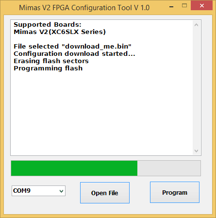
If the command was successful, you will see a few new files generated in the folder. One of the files will be download_me.bin. We will use this file to configure the Saturn Spartan 6 FPGA module. Run Mimas v2 flash configuration tool, select download_me.bin and click “program” button as in the image below (make sure to set the switch SW7 appropriately to allow flash download).
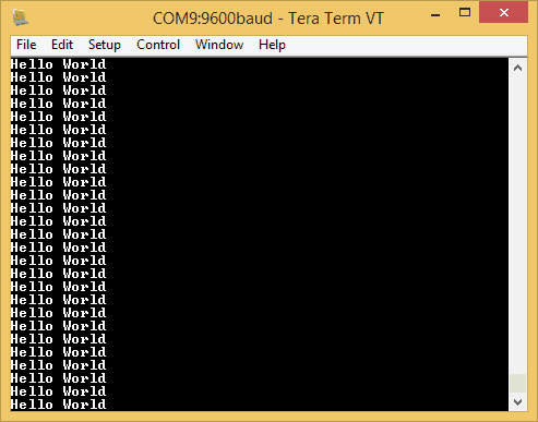
Put the switch SW7 on Mimas V2 to serial monitor mode and connect to the port using a serial terminal software (19200 baud). You should see the message “Hello World” being printed continuously.
Hello, I tried this tutorial. every step went well but I am not able to see any output in tera term. I set the serial port of tera term at 19200 baudrate. Do I need to do anything else. any suggestion please???
March 12, 2018 at 10:12 amPlease try with this BSP for MimasV2: https://productdata.numato.com/assets/downloads/fpga/mimasv2/mimasv2_base_system_builder_wizard.zip
March 13, 2018 at 4:34 amhi
this guide does not work for me. ALl i can see is my blue led constantly lit, but no output to console for speed 19200. BTW, printf is C++ code, you are referencing to C. Also your screenshot for Tera Term shows connection to COM9 using 9600…is that okat ?
June 20, 2018 at 7:59 amDoes this tutorial require us to have Xilinx’s 1000$ + software ?
April 23, 2019 at 12:39 amif you are using the new 14.7 linux vmbox make sure when you are in the step of creating a new hardware path you set it as follows:
target hardware: /home/ise/workspace/HelloWorld/edk/__xps/system.xml
bitstream and bmmfiles:
bitstream: /home/ise/workspace/HelloWorld/edk/implementation/helloWorld.bit
BMM file:
/home/ise/workspace/HelloWorld/edk/implementation/HelloWorld.bmm
When building copy the following files to one new directory:
/home/ise/workspace/HelloWorld/edk/implementation/HelloWorld.bit
/home/ise/workspace/HelloWorld/sdk/HelloWorld/Debug/HelloWorld.elf
/home/ise/workspace/HelloWorld/edk/implementation/HelloWorld_bd.bmm
final commands will be:
date2mem -bm HelloWorld_bd.bmm -bd HelloWorld.elf -bt HelloWorld.bit
promgen -w -p bin -u 00 HelloWorld_rp.bit -spi -o download_me
October 19, 2019 at 9:38 pm