Learning Verilog itself is not a difficult task, but creating a good design can be. But we focus on simple designs here and I will try my best to explain things as simple as possible. If you had been programming with procedural languages such as C, C++, you will have to make up your mind to understand that not all things happen sequentially in the digital world. A lot of things happen parallel too. When I started learning Verilog, I used to write code sequentially as if I was writing a C program. C programs are running on microprocessors, which execute one instruction at a time sequentially. So it is easy to write a program in a way how you want things to happen one step at a time. And if you look closely, this is the weak point of microprocessors/microcontrollers. They can do only one thing at a time, one and only one thing (of course I’m talking about single core devices!). But unlike microprocessors, digital circuits (FPGAs, CPLDs, and ASICs) can do many things at the same time. And you need to learn how to visualize many things happening at the same time in contrast to many things happening at different times, one thing at a time, in a procedural language.
Verilog Modules
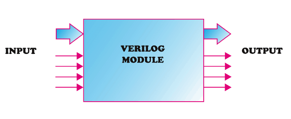
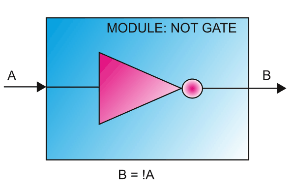
A Verilog module is a design unit similar to a black-box, with a specific purpose as engineered by the RTL designer. It has inputs, outputs and it functions as per its intended design. A simplest Verilog module could be a simple NOT gate, as shown in the second image below, whose sole job is to invert the incoming input signal. There is no upper bound on the complexity of the Verilog modules, they can even describe complete processor cores! Verilog deals with digital circuits. In Verilog realm, modules can be considered as equivalent to components in a digital circuit, as simple as a gate or a complex entity like ALU, counter etc… Modules are analogous to classes in C++ in a way that it is self-contained and give a finite number of methods (ports) to interact with the external world. Modules can be instantiated like classes are instantiated in C++ too. But beware; modules are not 100% similar to classes when it is implemented. For easy understanding, a module can be simply represented graphically as a box with a number of ports. The ports can be inputs, outputs or bidirectional. Ports can be single bit or multiple bits in width. The image below represents a module with a few inputs and outputs. The number of inputs and outputs, their width and direction will depend solely on the functionality of the module.
Fundamentally Verilog (or most HDLs for that matter) is all about creating modules, interconnecting them and managing the timing of interactions.
Enough talk, we didn’t even write a “Hello World” program yet. So how do we get our hands dirty with Verilog? Let us design a NOT gate in Verilog, simulate it and test it in a real hardware. A NOT gate (a.k.a an inverter) would be the simplest of all gates. The output of an inverter is always the negation of the input. ie; B = !A, where A is the input and B is the output. Below table summarize the behavior of NOT gate as a truth table.
| INPUT
A |
OUTPUT
B = NOT A |
|---|---|
| 0 | 1 |
| 1 | 0 |
NOT gate can be considered as a module with one input and one output with an internal behavior of B=!A. See the graphical representation of the inverter module below.
Let us see how we would represent this in Verilog.
module myModule(A, B);
    input wire A;
    output wire B;
    assign B = !A;
endmodule
Very simple isn’t it? let us go through each and every line and try to understand what is going on in this bit of code.
The name of the module is “myModule” and is declared using the “module” keyword. The keyword module in Verilog defines our module (called myModule) and assign two ports to it. Everything that goes into this module is placed in between “module” and “end module” keywords. myModule has two ports. The ports’ size or direction is not known yet.
In the two lines below, port A and port B are declared as input and output respectively. I’m sure you are curious about what the keyword “wire” is doing there! Well, in Verilog there are two fundamental data types, ‘wire’ and ‘reg’. There are many other data types like int, real etc… But ‘wire’ and ‘reg’ plays very important roles in Verilog, that without learning them we cannot progress much.
As I mentioned before, knowing a little digital electronics will come handy here. ‘wire’ is just like a physical wire that we use to connect two different things electrically. If a potential is applied at one end of a copper wire, it will show up on the other end of the wire as long as you keep applying the potential. As soon as you remove the input, the potential is gone. This is true for a ‘wire’ data type in Verilog as well. A wire will have a particular logic state as long as it is driven by some other entity. If nobody is driving the wire, it will be in an unknown state. In Verilog, ‘wire’ can be used to connect things within a module or between two modules.
On the other hand, ‘reg’ can store a logic state and maintain it until someone changes it (think about a register in a microcontroller). This is similar to a flip-flop. If you put flip-flop in one state, it will remain in that state until somebody changes it.
So you can use wire as input or output for a module and ‘reg’ can be used as an output of a module. When wire is used as output, there should be a ‘reg’ that drives the wire from within the module so that ‘wire’ will have some meaningful information on it. If ‘reg’ is used as output, no other mechanism is necessary since it can hold data on its own.
Then why “myModule” has both input and output declared as wires? Good question, the answer is, because the module represents a NOT gate. Gates never store any state. Gates are purely combinational; i.e. its output always depends on the current input. If there is some logic state applied to its input then there will be a corresponding output (B = !A in this case). If no logic state is applied to the input it is considered as unknown state and the output state will also be unknown. And this also implies that to have any useful output from this module, some other entity should be driving its input from somewhere else (keep this in mind, we will touch this subject later when talking about test bench).
One more important thing about the above code is the keyword “assign”. The assign keyword is used to create combinational circuits. Whatever written on the right side of equal sign in the statement will be evaluated and the result will be assigned to the entity on the left side and this happens asynchronously. As soon as any changes happen on the right side, the result will be reflected on the left side. If you find it difficult to understand this, you may want to read a little about combinational digital circuits.
Now that we have a piece of code, we may want to simulate the code to see if it is working as expected. Simulation, in a broad sense, is the process of giving some known input and generating the corresponding output. The output is expected to be dependent on both the input and the behavior of the module under test. When the output is verified against expected output, it is called verification. There are many tools available for simulation and verification. Here we will be using the inbuilt simulator (part of Xilinx Vivado Design Suite) for simulation and waveform inspection.
Back to part 1 Continue to part 3
Your words are very useful .they help me a lot .thanks
January 17, 2019 at 9:27 ambest wishes!
chen
your words are very useful.. they help me a lot.thanks!
January 17, 2019 at 9:29 ambest wishes!