Introduction
PetaLinux is a development environment provided by Xilinx for creating embedded Linux systems targeted for their FPGA devices. It offers a streamlined workflow for building custom Linux distributions tailored to the specific requirements of embedded applications running on Xilinx FPGAs. It offers the developer the flexibility, scalability, and robustness for a wide range of embedded applications. It simplifies the process of integrating custom hardware IP cores, drivers, and user applications into a unified Linux-based platform. This article will help you to create PetaLinux project and run it on TityraCore Z7 SODIMM FPGA. So, let’s jump straight into it.
Structure to run the PetaLinux
- Section 1: Creating the Zynq7 processor based design on TityraCore Z7
- Section 2: Creating the PetaLinux project
- Section 3: Adding the Devicetree
- Section 4: Building the project and Running PetaLinux on TityraCore Z7
Prerequisites:
For following this article, you would require:
- Hardware:
- TityraCore Z7 SODIMM FPGA
- TityraCore Z7 carrier board.
- Xilinx Platform Cable JTAG debugger
- Ethernet Cable
- USB type C cable
- Software:
- Xilinx Vivado 2023.2.1 installed on either Windows or Linux system
- Linux system( Ubuntu 20.04.6 LTS)
- PetaLinux 2023.2.1
Section 1: Creating the Zynq7 processor based design on TityraCore Z7
Step 1:
Download and install Vivado Board Support Package files for Tityra from here. Follow the readme in the link on how to install Vivado Board Support Package files for Numato Lab’s boards.
Step 2:
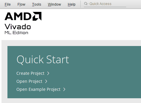
Start Vivado Design Suite, and select “Create Project” from Quick Start section. The project wizard will pop up. Press next to proceed with creating the project.
Step 3:
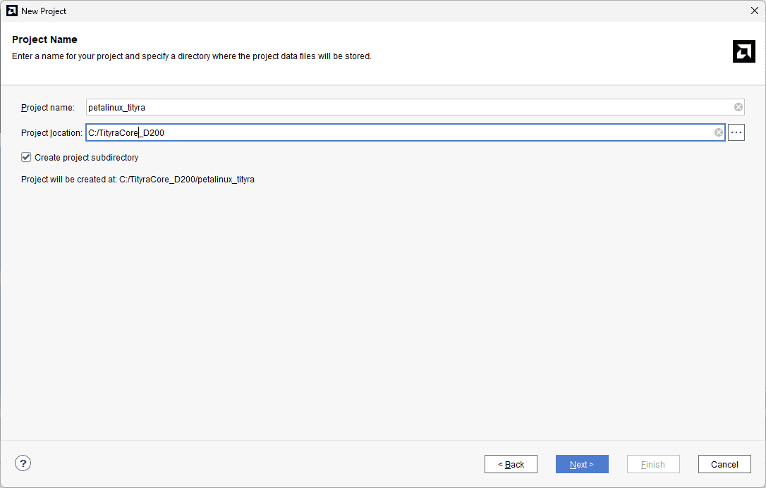
Type in a project name and save it at a convenient location. For this example “petalinux_tityra” is used as project name, but feel free to use any name. Select the check box below to keep all project files in a single folder. The image below shows the settings for the example project. Click “Next” to continue.
 Step 4:
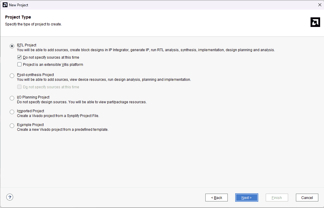
Choose “RTL Project” as project type and check the option “Do not specify sources at this time”.
Step 5:
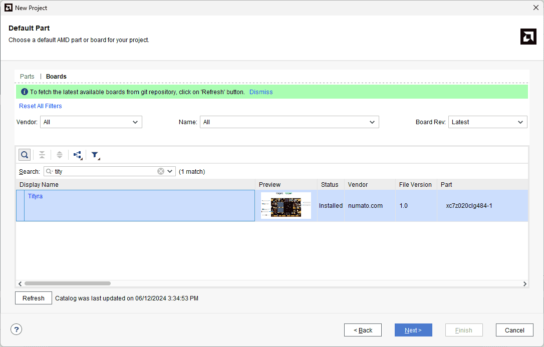
At the “Default Part” step, select “Boards” and choose Vendor as “numato.com”. Select “Tityra” and click “Next”. If tityra is not displayed in the boards list, you will need to install tityra board support files correctly.
Step 6:
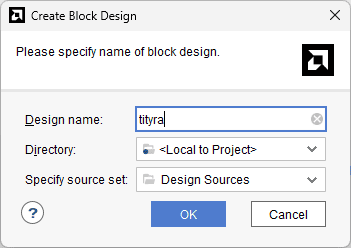
Under Flow Navigator, select “Create Block Design” in IP Integrator. Give an appropriate name to design. We will call it “tityra” for example.
Step 7:
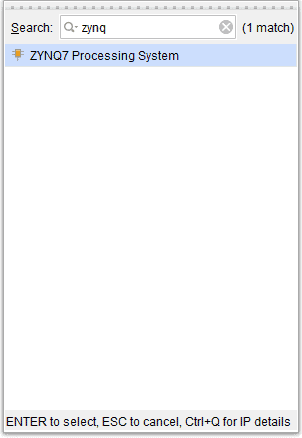
Go to Diagram window, right click and select “Add IP” from the popup menu. Search for ZYNQ7 Processing System. Add it to block design by double clicking.
Step 8:
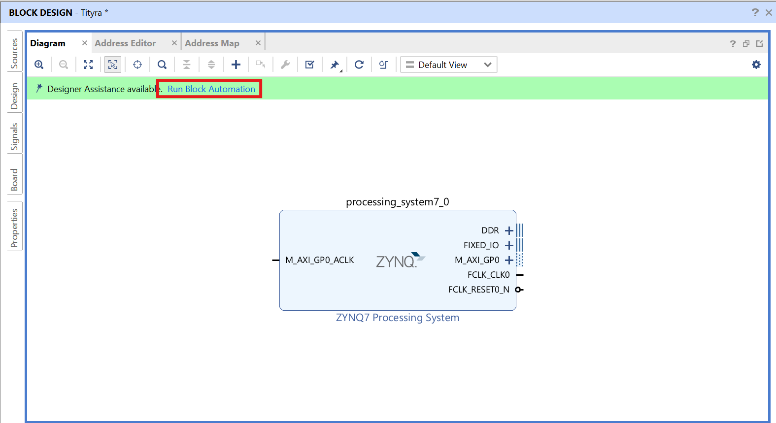
Click on “Run Block Automation” option on the green bar.
Step 9:
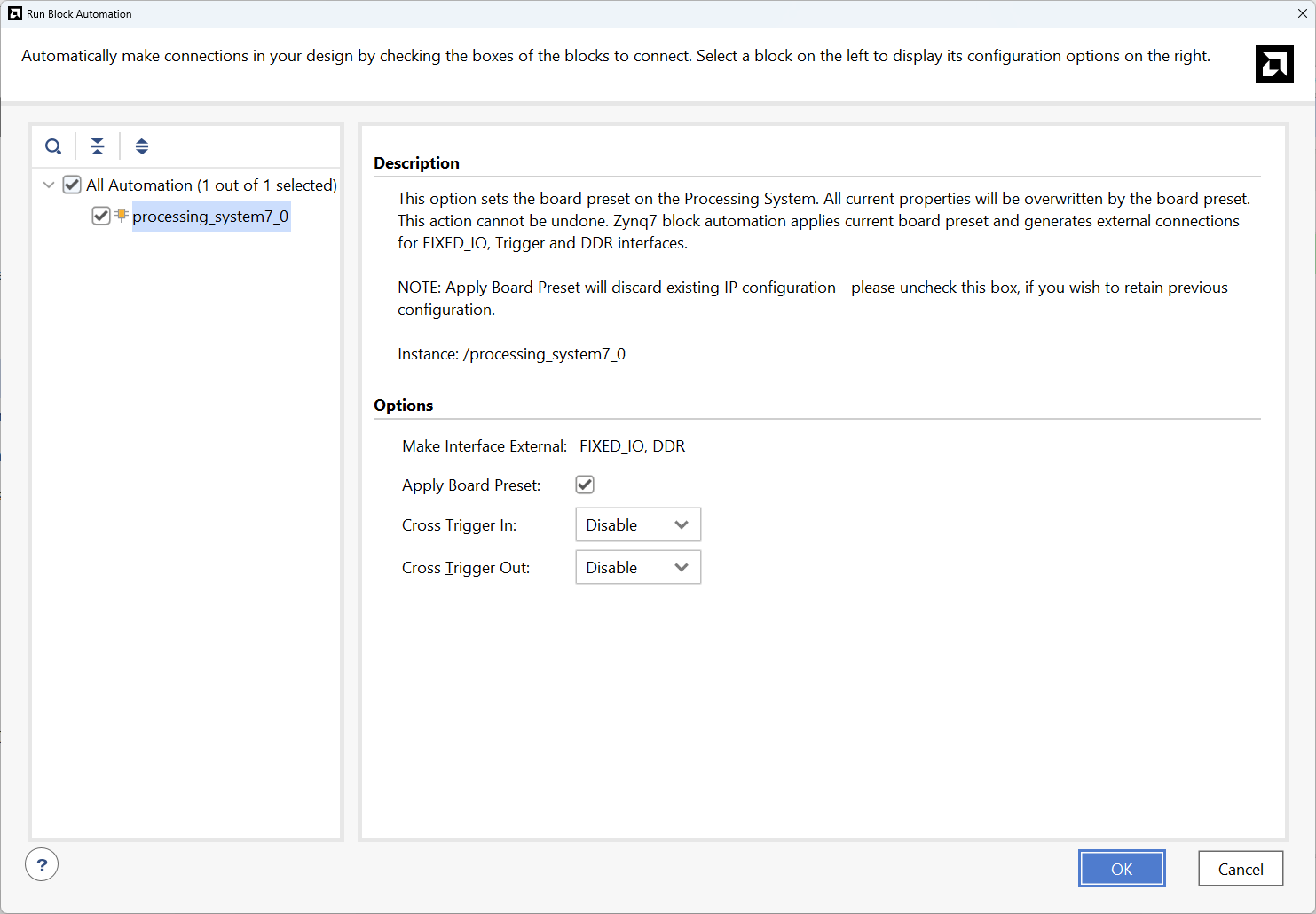
In the “Run Block Automation” window, select the options as in image below and click OK.
Step 10:
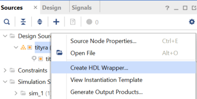
Go to “Sources” tab, right click on “tityra” design file and select “Create HDL Wrapper”. Click OK on the window that appears to finish generating wrapper.
Step 11:
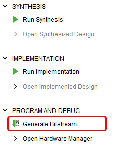
Click “Generate Bitstream” under PROGRAM AND DEBUG section and click “Yes” in any subsequent dialog window which comes up.
Step 12:
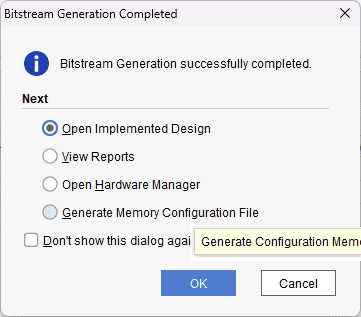
Once the bitstream is successfully generated, close any “Bitstream Generation Completed” dialog which comes up asking for what to do next.
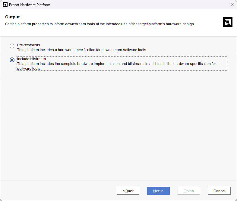
Go to File -> Export -> Export Hardware…
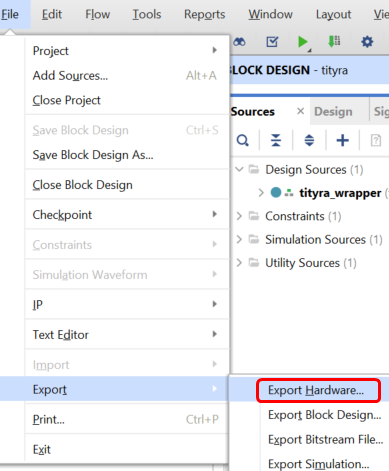
Check “Include bitstream”, keep “Export to:” default, and click OK.
Step 13:
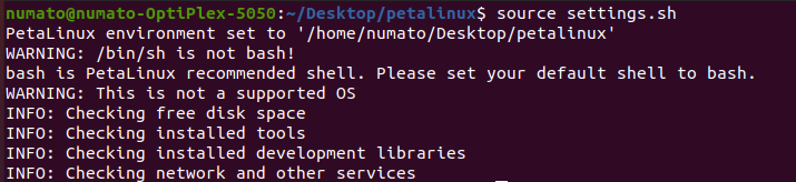
Open terminal in the location of PetaLinux installation Directory and Set Up PetaLinux Working Environment.
source <path-to-installed-PetaLinux>/settings.sh
Step 14:
Create new project in a convenient location using zynq template. For this example, “tityra_peta” is used as project name, but feel free to use any name. Type the command given below.
petalinux-create -t project -n New_project/tityra_peta --template zynq
Change the working directory to newly created project location using the command:
cd New_Project/tityra_peta

Step 15:
Include the XSA file, which is generated in the Vivado Design Suite, to this location by specifying the appropriate path.
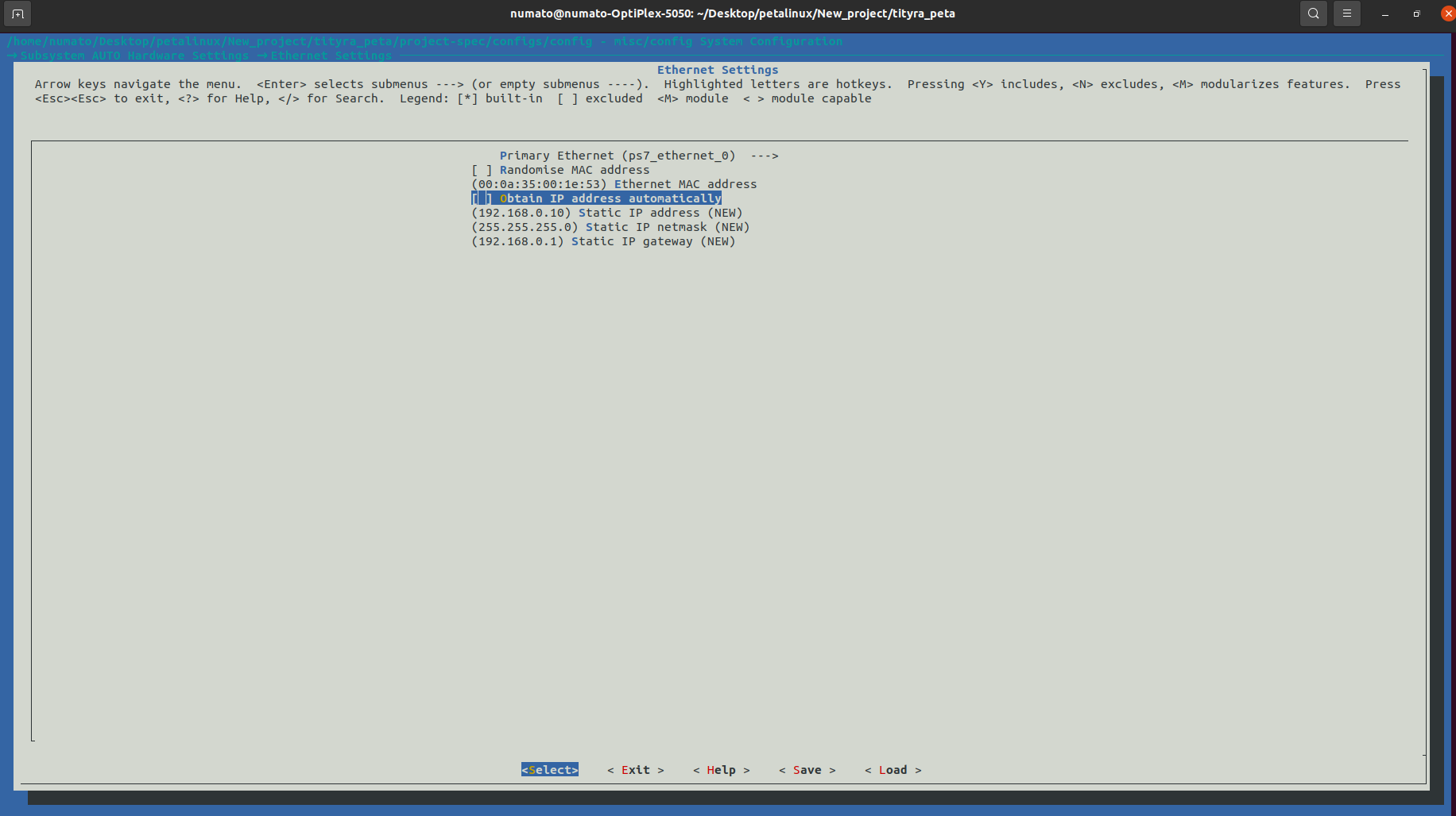
petalinux-config --get-hw-description=<path-to-xsa>/tityra_wrapper.xsa
A misc/config system configuration menu will appear, go to Subsystem AUTO Hardware Settings –> Ethernet Settings –> unselect Obtain IP address automatically. Keep all other settings as default and Exit the configuration menu by selecting Exit–> Yes.
Step 16:
Execute the provided command to configure the root file system, and rootfs menu will appear.
petalinux-config -c rootfs
Enable the following packages:
- Filesystem packages –> admin –> sudo –> sudo
- Filesystem packages –> base –> i2c – tools –> i2c – tools
- Filesystem packages –> console –> network –> dropbear –> dropbear
- Filesystem packages –> console –> network –> ethtool –> ethtool
- Filesystem packages –> console –> utils –> grep –> grep
- Image Features –> auto – login
Save and exit the configuration file.
Step 17:
Add the following lines to the devicetree file located in <path-to-project>/ project-spec/meta-user/recipes-bsp/device-tree/files/system-user.dtsi
&gem1 {
   phy-handle = <&phy1>;
   ps7_ethernet_1_mdio: mdio {
      #address-cells = <1>;
      #size-cells = <0>;
      phy1: phy@0 {
         compatible = "micrel,ksz9031";
         device_type = "ethernet-phy";
         reg = <0>;
      };
   };
};

/ {
    usb_phy0:usb_phy@0 {
        compatible="usb-nop-xceiv";
        #phy-cells = <0>;
    };
};

&usb0 {
   dr_mode = "otg";
   usb-phy = <&usb_phy0>;
};

&i2c0 {
  status = "okay";
  clock-frequency = <400000>;
  #address-cells = <1>;
        #size-cells = <0>;
        eeprom: eeprom@51
            {
               compatible = "atmel,24c02";
               reg = <0x51>;
            };
};

&i2c1 {
    status = "okay";
    clock-frequency = <100000>;
    #address-cells = <1>;
    #size-cells = <0>;

    //  RTC
    rtc0:rtc-ti@68 {
             compatible = "ti,bq32000";
             reg = <0x68>;
    };
};
Step 18:
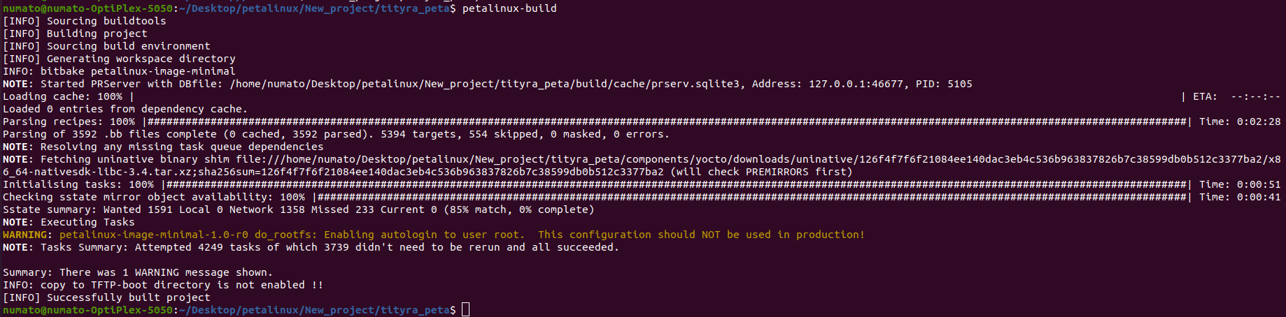
Now build the entire project using the command mentioned below. This will take a while.
petalinux-build
Step 19:
After building the project successfully, let’s powerup the board for programming. Make sure the board is in JTAG boot mode configuration. Open any serial terminal (Putty, TeraTerm..) for observing output and connect Ethernet cable to check ethernet connectivity. Use the following command for programming the board.
petalinux-boot --jtag --u-boot --fpga --kernel
Step 20:
If everthing went well, the board will start booting.
To check whether the ethernet connection is established, use the command:
ifconfig -a
You will get the output as shown below.
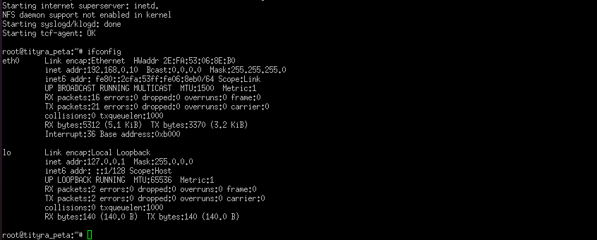
This approach allows us to test various functionalities such as OTG, MAC ID of EEPROM, RTC, and more.