Introduction:
SD cards and eMMC (embedded MultiMediaCard) are versatile storage solutions for embedded systems, enabling efficient data storage and retrieval. The TityraCore D200 FPGA, with its ARM Cortex-A9 Processing System (PS), integrates a dedicated SD/eMMC controller, making it ideal for testing storage interfaces.
This project focuses on performing read and write tests for SD cards and eMMC to validate their functionality and reliability. The SD/eMMC controller in the Zynq PS is utilized to handle low-level communication with storage devices, while file system operations ensure data consistency.
The test demonstrates end-to-end data handling, including initialization, writing data to storage, and verifying the integrity of the data through read operations. This design provides a robust foundation for developing and testing storage-related applications on the Zynq platform.
Prerequisites:
Hardware:
- TityraCore D200 SODIMM Module.
- TityraCore SoC carrier.
- SD Card.
- AMD Platform Cable II JTAG debugger.
- USB Type C Cable.
Software:
- AMD Vivado Design Suite 2025.1
- Vitis 2025.1
- PUTTY Serial terminal.
Let’s get Started
The following steps will walk you through the process of creating a new project with Vivado and building a hardware platform with Zynq processing system using IP integrator. This article is written for Numato Lab’s Tityra core D200 Module, but can be adapted to any other Zynq based platform with minor changes. Screenshots are added wherever possible to make the process easier to the reader.
Step 1:
Start Vivado Design Suite, and select “Create New Project” from Quick Start section. The project wizard will pop up. Press next to proceed with creating the project.
Step 2:
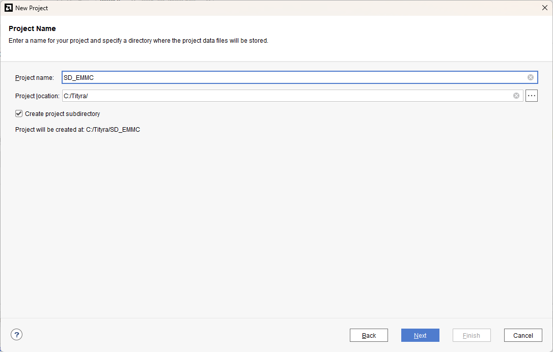
Type in a project name and save it at a convenient location. For this example “SD_EMMC” is used as project name, but feel free to use any name. Select the check box below to keep all project files in a single folder. The image below shows the settings for the example project. Click “Next” to continue.
Step 3:
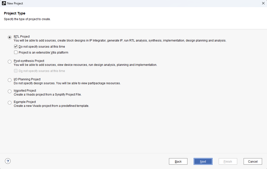
Choose “RTL Project” as project type and check the option “Do not specify sources at this time”.
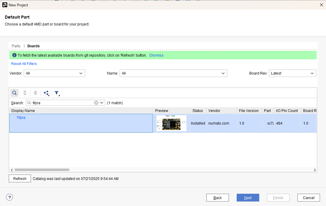
Step 4:
At the “Default Part” stage, switch to the “Boards” tab and set the vendor to numato.com. Select “Tityra” and click Next.If the Tityra board does not appear in the list, click “Refresh” to update the board catalog. Vivado will then download the latest board files, after which Tityra will become available for selection.
Continue the wizard and finish creating the project. When the new project wizard exits, a new project will be opened up in Vivado with the settings you have selected.
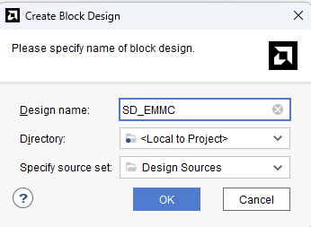
Step 5:
Under Flow Navigator, select “Create Block Design” in IP Integrator. Give an appropriate name to design. We will call it “SD_EMMC” for example.
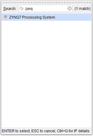
Step 6:
Go to Diagram window, right click and select “Add IP” from the popup menu. Search for ZYNQ7 Processing System. Add it to block design by double clicking.
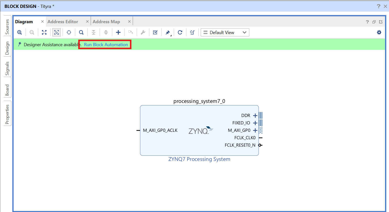
Step 7:
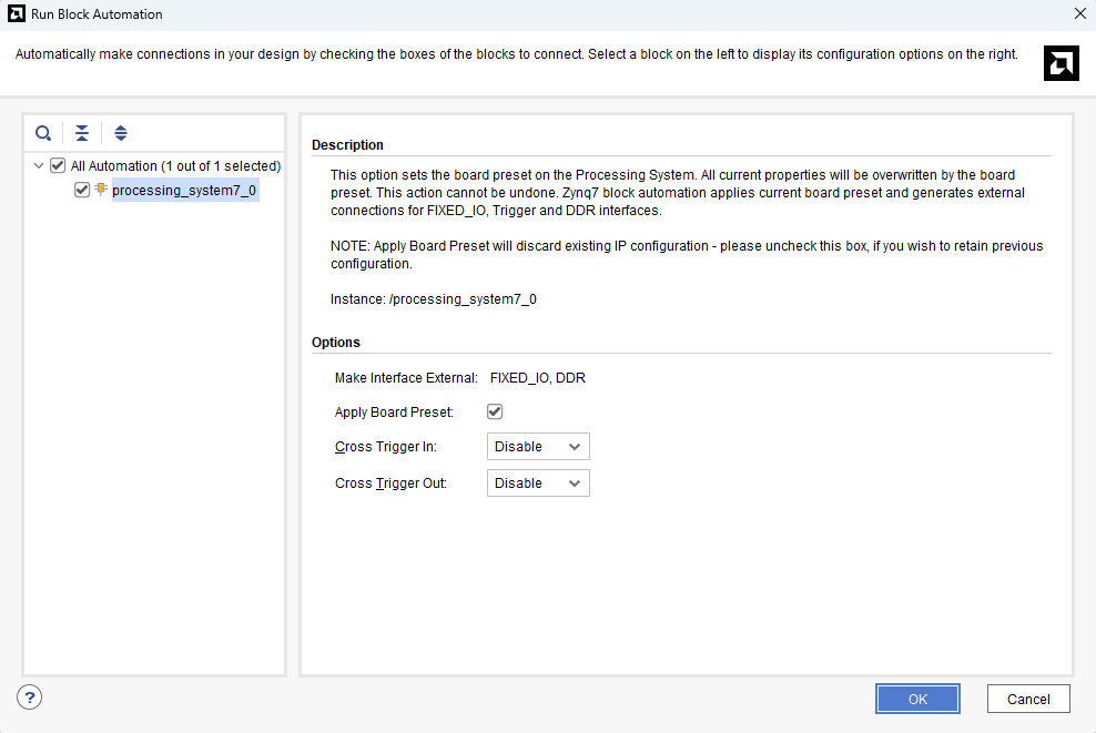
Click on “Run Block Automation” option on the green bar.
Step 8:
In the “Run Block Automation” window, select the options as in image below and click OK.
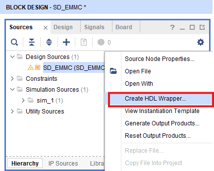
Step 9:
Go to “Sources” tab, right click on “SD_EMMC” design file and select “Create HDL Wrapper”. Click OK on the window that appears to finish generating wrapper.
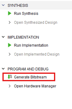
Step 10:
Click “Generate Bitstream” under PROGRAM AND DEBUG section and click “Yes” in any subsequent dialog window which comes up asking for what to do next .
Step 11:
Once the bitstream is successfully generated, close any “Bitstream Generation Completed” dialog which comes up asking for what to do next , click OK.
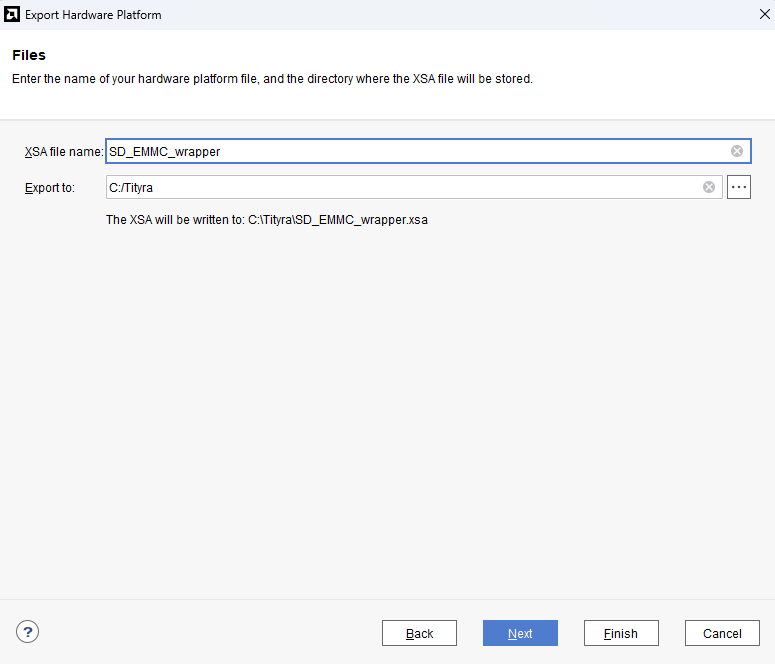
Go to File -> Export -> Export Hardware…
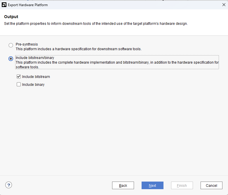
Check “Include bitstream”, keep “Export to:” default, and click OK.
Step 12:
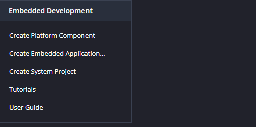
Launch Vitis IDE and create a new platform for the project, by selecting “Create Platform Component”, click “Next”, in the Flow tab select the XSA file saved using the step 15 and finally click “Next” and “Finish” respectively.
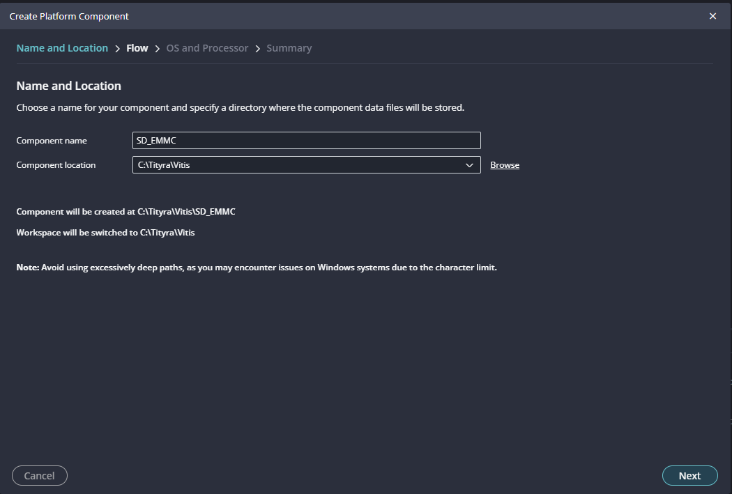
Step 13:
Give the component name and the platform location and click on “Next”.
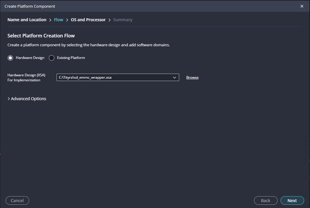
Step 14:
In the next tab browse the XSA file , select it , click on “Next”. In the next OS and Processor tab click “Next” and “Finish”.
After successful creation of the platform, build the platform.
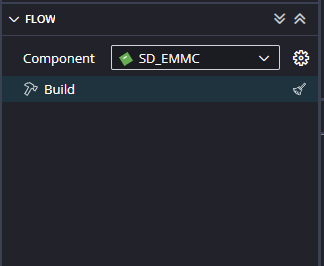
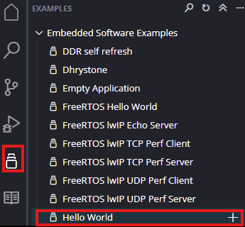
Step 15:
Next create the Hello world Application component by selecting the “Hello world” template from the “examples”.
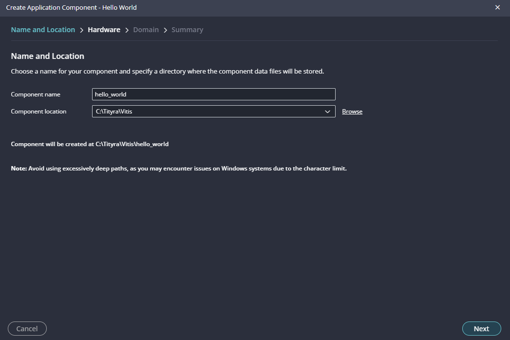
In “Create Application Component” tab specify project name and location, click “Next”.
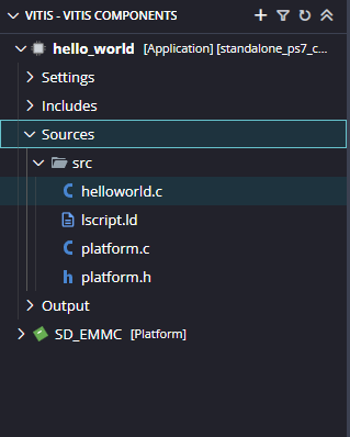
Select newly created Platform and click “Next”.
When the Helloworld project is added successfully, open the “helloworld.c” file from Explorer tab and replace the C code with the code given below:
/******************************************************************************
* Copyright (C) 2019 - 2022 Xilinx, Inc.  All rights reserved.
* SPDX-License-Identifier: MIT
******************************************************************************/

/*****************************************************************************/
/**
*
* @file xsdps_raw_example.c
*
* This example is used to test read and write transfers on SD/eMMC interface.
*
* Please note that running this example will modify the card contents and
* file system information will be erased in the card. Card will need to be
* re-formatted.
*
* Modify the offset and Size macros to test different SD memory offset and
* size.
*
* <pre>
* MODIFICATION HISTORY:
*
* Ver	Who	Date     Changes
* ----- --- -------- ---------------------------------------------
* 3.9 	mn  12/02/19 First release
* 3.10	mn  09/17/20 Fix sector offset issue with Non-HCS SD cards
*
*</pre>
*
******************************************************************************/

/***************************** Include Files *********************************/

#include "xsdps.h"		/* SD device driver */

/************************** Constant Definitions *****************************/

/**************************** Type Definitions *******************************/

/***************** Macros (Inline Functions) Definitions *********************/

/************************** Function Prototypes ******************************/
static int SdpsRawTest(void);

/************************** Variable Definitions *****************************/

#ifdef __ICCARM__
#pragma data_alignment = 32
u8 DestinationAddress[10*1024];
#pragma data_alignment = 32
u8 SourceAddress[10*1024];
#else
u8 DestinationAddress[10*1024] __attribute__ ((aligned(32)));
u8 SourceAddress[10*1024] __attribute__ ((aligned(32)));
#endif

#define TEST 7
/* Number of SD blocks to test */
#define NUM_BLOCKS 16
/* Sector offset to test */
#define SECTOR_OFFSET 204800


/*****************************************************************************/
/**
*
* Main function to call the SD example.
*
*
* @return	XST_SUCCESS if successful, otherwise XST_FAILURE.
*
* @note		None
*
******************************************************************************/
void test_emmc();
void test_sdcard();
int Status;

int main()
{
	print("\r\n\r\nWelcome to TityraCore SD eMMC Tests. Thank You.\r\n\n");
			test_sdcard();
			test_emmc();

    		print("\r\n\r\nTityraCore SD eMMC Tests Finished. Thank You.\r\n\n");
    	    return 0;
}

int SdpsRawTest(void){
	print("\r\n\r\n\e[1;33mSD Card Test\e[0m\r\n");
	print("\e[1;33m*****************\e[0m\r\n\r\n");

	static XSdPs SdInstance;
		XSdPs_Config *SdConfig;
		int Status;
		u32 BuffCnt;
		/*
		 * Since block size is 512 bytes. File Size is 512*BlockCount.
		 */
		u32 FileSize = (512*NUM_BLOCKS); /* File Size is only up to 2MB */
		u32 Sector = SECTOR_OFFSET;

		for(BuffCnt = 0; BuffCnt < FileSize; BuffCnt++){
			SourceAddress[BuffCnt] = TEST + BuffCnt;
		}

		/*
		 * Initialize the host controller
		 */
		SdConfig = XSdPs_LookupConfig(XPAR_XSDPS_0_BASEADDR); // Or XPAR_XSDPS_0_BASEADDR, etc.
		if (NULL == SdConfig) {
			xil_printf("SD Raw Read/ Write Test failed \r\n");
			return XST_FAILURE;
		}

		Status = XSdPs_CfgInitialize(&SdInstance, SdConfig,
						SdConfig->BaseAddress);
		if (Status != XST_SUCCESS) {
			xil_printf("SD Raw Read/ Write Test failed \r\n");
			return XST_FAILURE;
		}

		Status = XSdPs_CardInitialize(&SdInstance);
		if (Status != XST_SUCCESS) {
			xil_printf("SD Raw Read/ Write Test failed \r\n");
			return XST_FAILURE;
		}

		/*
		 * Write data to SD.
		 */
		if (!(SdInstance.HCS)) Sector *= XSDPS_BLK_SIZE_512_MASK;
		Status = XSdPs_WritePolled(&SdInstance, Sector, NUM_BLOCKS,
					   SourceAddress);
		if (Status != XST_SUCCESS) {
			xil_printf("SD Raw Read/ Write Test failed \r\n");
			return XST_FAILURE;
		}

		/*
		 * Read data from SD.
		 */
		Status  = XSdPs_ReadPolled(&SdInstance, Sector, NUM_BLOCKS,
					   DestinationAddress);
		if (Status!=XST_SUCCESS) {
			xil_printf("SD Raw Read/ Write Test failed \r\n");
			return XST_FAILURE;
		}

		/*
		 * Data verification
		 */
		for(BuffCnt = 0; BuffCnt < FileSize; BuffCnt++){
			if(SourceAddress[BuffCnt] != DestinationAddress[BuffCnt]){
				xil_printf("SD Raw Read/ Write Test failed \r\n");
				return XST_FAILURE;
			}
		}
		xil_printf("Successfully ran SD Raw Read/ Write Test \r\n");
		return XST_SUCCESS;
}

void test_sdcard(){
	Status = SdpsRawTest();
}

int SdpsRawTest1(void){
	print("\r\n\r\n\e[1;33meMMC Test\e[0m\r\n");
	print("\e[1;33m*****************\e[0m\r\n\r\n");

	static XSdPs SdInstance;
		XSdPs_Config *SdConfig;
		int Status;
		u32 BuffCnt;
		/*
		 * Since block size is 512 bytes. File Size is 512*BlockCount.
		 */
		u32 FileSize = (512*NUM_BLOCKS); /* File Size is only up to 2MB */
		u32 Sector = SECTOR_OFFSET;

		for(BuffCnt = 0; BuffCnt < FileSize; BuffCnt++){
			SourceAddress[BuffCnt] = TEST + BuffCnt;
		}

		/*
		 * Initialize the host controller
		 */
		SdConfig = XSdPs_LookupConfig(XPAR_XSDPS_1_BASEADDR);
		if (NULL == SdConfig) {
			xil_printf("eMMC Raw Read/ Write Test failed \r\n");
			return XST_FAILURE;
		}

		Status = XSdPs_CfgInitialize(&SdInstance, SdConfig,
						SdConfig->BaseAddress);
		if (Status != XST_SUCCESS) {
			xil_printf("eMMC Raw Read/ Write Test failed \r\n");
			return XST_FAILURE;
		}

		Status = XSdPs_CardInitialize(&SdInstance);
		if (Status != XST_SUCCESS) {
			xil_printf("eMMC Raw Read/ Write Test failed \r\n");
			return XST_FAILURE;
		}

		/*
		 * Write data to eMMC.
		 */
		if (!(SdInstance.HCS)) Sector *= XSDPS_BLK_SIZE_512_MASK;
		Status = XSdPs_WritePolled(&SdInstance, Sector, NUM_BLOCKS,
					   SourceAddress);
		if (Status != XST_SUCCESS) {
			xil_printf("eMMC Raw Read/ Write Test failed \r\n");
			return XST_FAILURE;
		}

		/*
		 * Read data from eMMC.
		 */
		Status  = XSdPs_ReadPolled(&SdInstance, Sector, NUM_BLOCKS,
					   DestinationAddress);
		if (Status!=XST_SUCCESS) {
			xil_printf("eMMC Raw Read/ Write Test failed \r\n");
			return XST_FAILURE;
		}

		/*
		 * Data verification
		 */
		for(BuffCnt = 0; BuffCnt < FileSize; BuffCnt++){
			if(SourceAddress[BuffCnt] != DestinationAddress[BuffCnt]){
				xil_printf("eMMC Raw Read/ Write Test failed \r\n");
				return XST_FAILURE;
			}
		}
		xil_printf("Successfully ran eMMC Raw Read/ Write Test \r\n");
		return XST_SUCCESS;
}

void test_emmc(){
	Status = SdpsRawTest1();
}
After adding the source file build the Project.
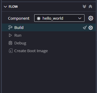
Step 16:
Once the build is completed successfully, power up TityraCore D200 using an external DC power supply and connect the AMD Platform USB cable to the board.
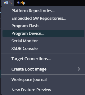
Step 17:
Program the FPGA on TityraCore D200 by selecting the Program Device option from the Vitis menu.
Step 18:
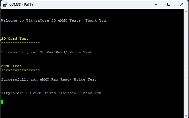
Open the COM port corresponding to TityraCore D200 in any serial terminal (PuTTY, Tera Term, etc.) with a 115200 baud rate.
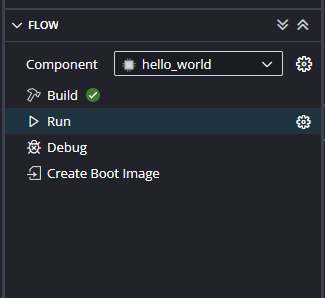
Step 19:
After FPGA is successfully programmed, click on the “Run” button.
If everything went well, the application running on the board should print the following information over the UART and should be displayed on the Serial Terminal application.