Introduction:
Ethernet is a widely used protocol in the TCP/IP stack, enabling device communication in LANs. The TityraCore D200 FPGA, with its integrated ARM Cortex-A9 Processing System (PS) and programmable logic (PL), is an ideal platform for Ethernet-based applications. This design demonstrates an echo server application using the lightweight IP (lwIP) TCP/IP stack, where the server receives and echoes back TCP data.
The Zynq Processing System utilizes the Gigabit Ethernet MAC (GEM) to interface with an external PHY chip via the Reduced Gigabit Media-Independent Interface (RGMII). This setup highlights the seamless integration of hardware and software for high-speed Ethernet communication, making the TityraCore D200 FPGA a robust solution for networking applications.
Prerequisites:
Hardware:
- TityraCore D200 SODIMM Module.
- TityraCore SoC carrier.
- Cat 6 Ethernet Cable.
- USB Type C Cable.
Software:
- AMD Vivado Design Suite 2025.1
- Vitis Unified 2025.1
- PUTTY Serial terminal.
Let’s get Started
The following steps will walk you through the process of creating a new project with Vivado and building a hardware platform with Zynq processing system using IP integrator. This article is written for Numato Lab’s Tityra core D200 Module, but can be adapted to any other Zynq based platform with minor changes. Screenshots are added wherever possible to make the process easier to the reader.
Step 1:
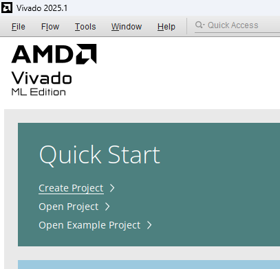
Start Vivado Design Suite, and select “Create New Project” from Quick Start section. The project wizard will pop up. Press next to proceed with creating the project.
Step 2:
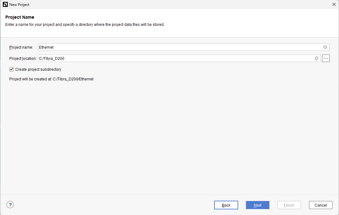
Type in a project name and save it at a convenient location. For this example “Ethernet_echo” is used as project name, but feel free to use any name. Select the check box below to keep all project files in a single folder. The image below shows the settings for the example project. Click “Next” to continue.
Step 3:
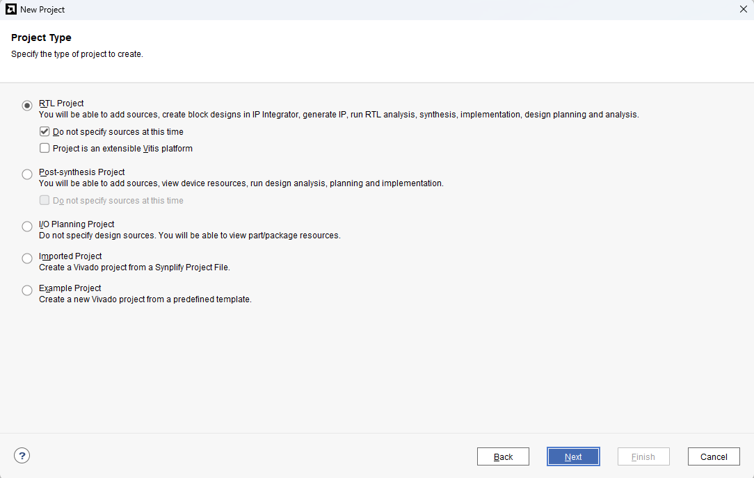
Choose “RTL Project” as project type and check the option “Do not specify sources at this time”.
Step 4:
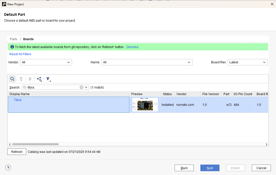
At the “Default Part” stage, switch to the “Boards” tab and set the vendor to numato.com. Select “Tityra” and click Next.If the Tityra board does not appear in the list, click “Refresh” to update the board catalog. Vivado will then download the latest board files, after which Tityra will become available for selection.
Step 5:
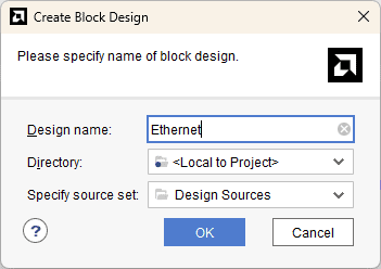
Under Flow Navigator, select “Create Block Design” in IP Integrator. Give an appropriate name to design. We will call it “Ethernet” for example.
Step 6:
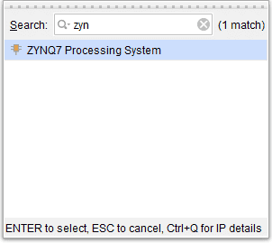
Go to Diagram window, right click and select “Add IP” from the popup menu. Search for ZYNQ7 Processing System. Add it to block design by double clicking.
Step 7:
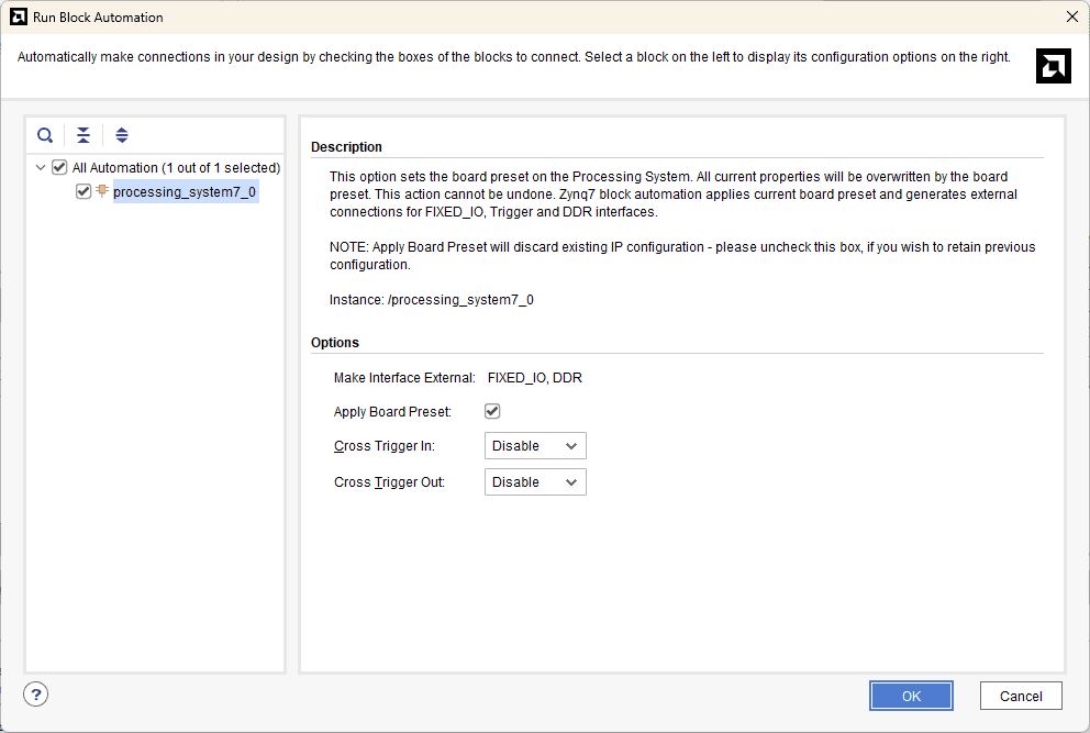
In the “Run Block Automation” window, select the options as in image below and click OK.
Step 8:
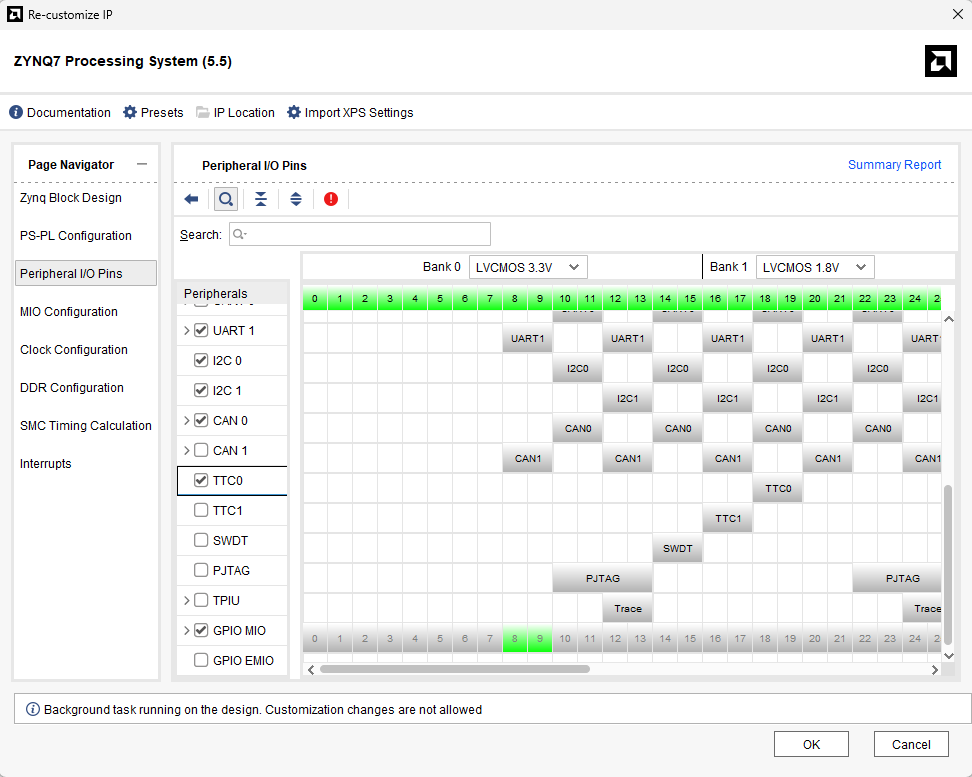
After running “Block Automation” double click on ZYNQ7 Processing system to open the customize window and go the the Peripheral IO pins section and enable the “TTC0” and click OK.
Step 9:
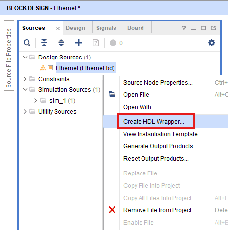
Go to “Sources” tab, right click on “Ethernet” design file and select “Create HDL Wrapper”. Click OK on the window that appears to finish generating wrapper.
Step 10:
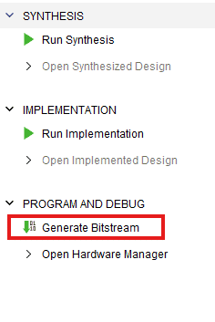
Click “Generate Bitstream” under PROGRAM AND DEBUG section and click “Yes” in any subsequent dialog window which comes up.
Step 11:
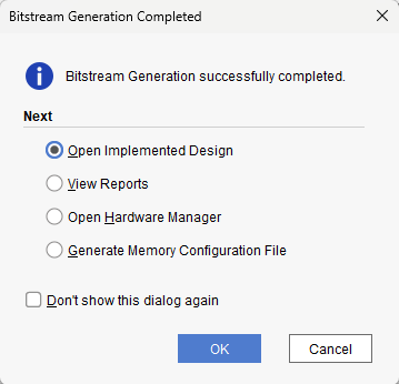
Once the bitstream is successfully generated, close any “Bitstream Generation Completed” dialog which comes up asking for what to do next.
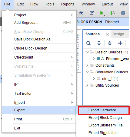
Go to File -> Export -> Export Hardware…
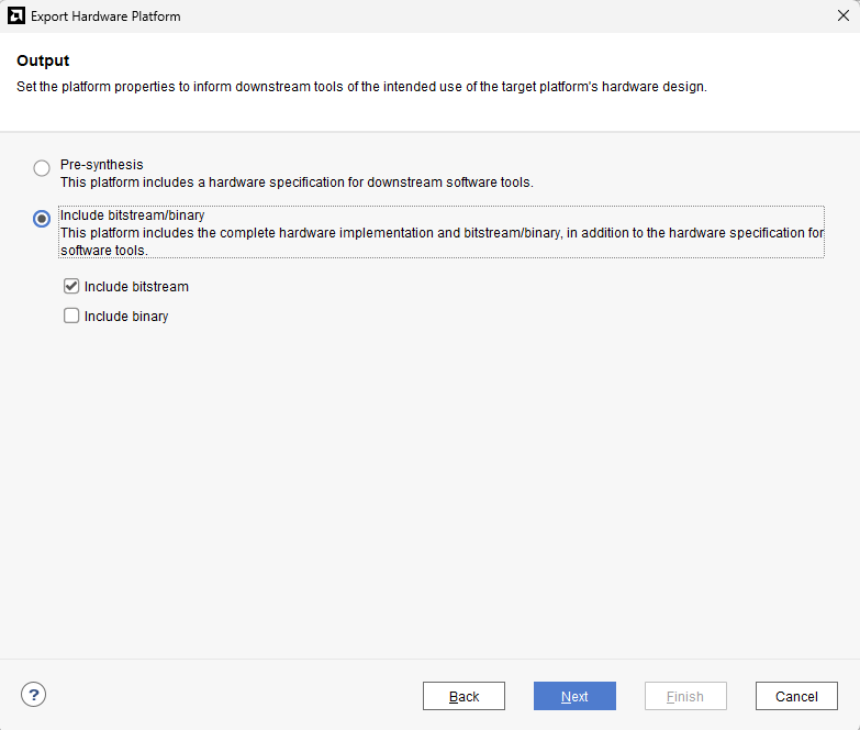
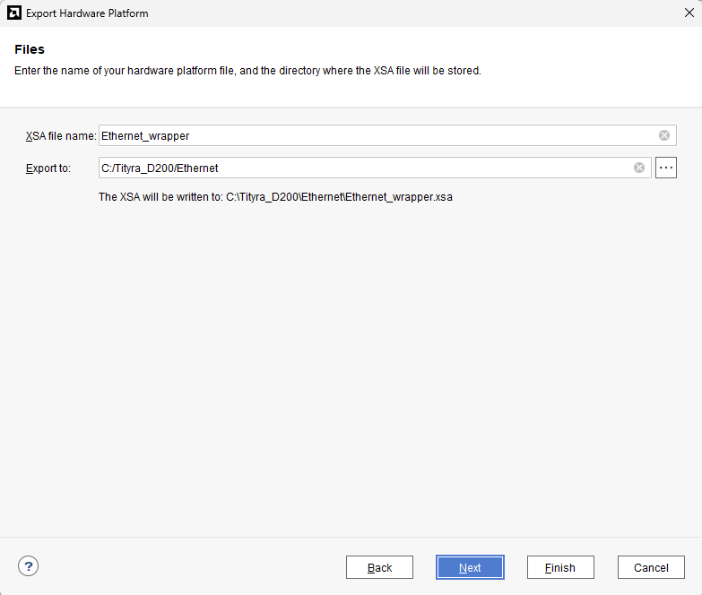
Check “Include bitstream”, keep “Export to:” default, and click OK.
Step 12:
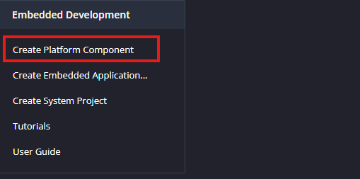
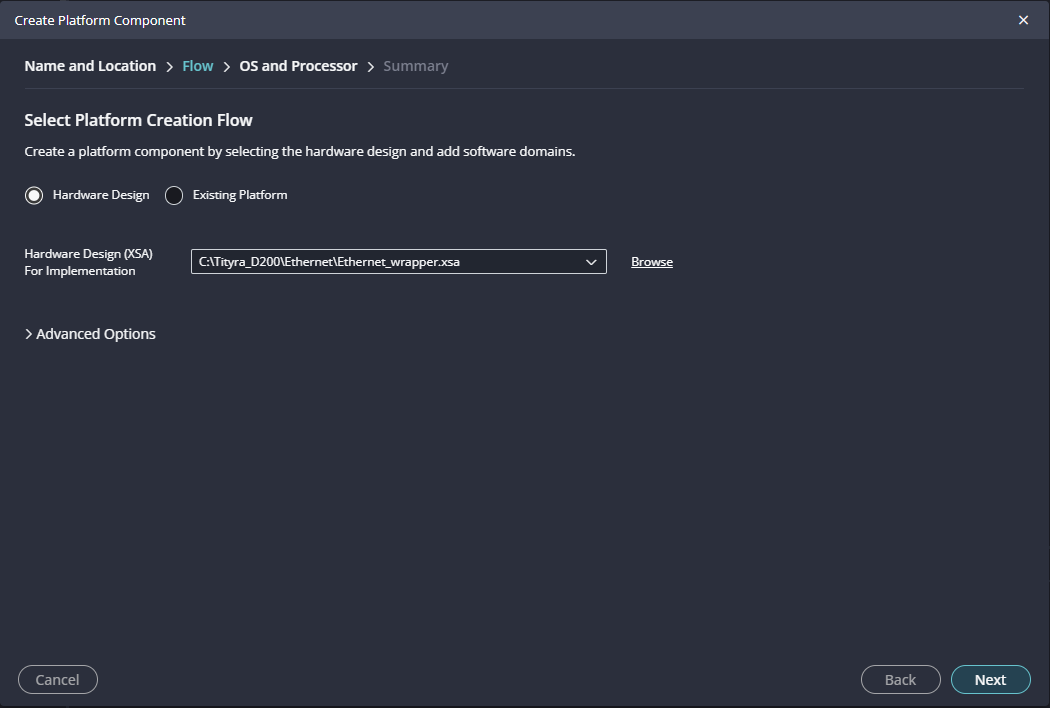
Launch Vitis IDE and create a new platform for the project, by selecting “Create Platform Component”, click “Next”, in the Flow tab select the XSA file saved and finally click “Next” and “Finish” respectively.
Step 13:
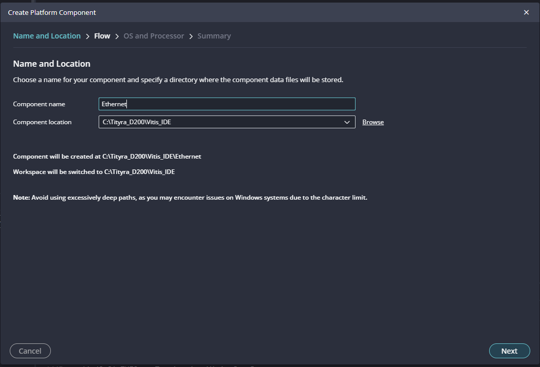
Give the component name and the platform location and click on “Next”.
Step 14:
In the next tab browse the XSA file , select it , click on “Next”. In the next OS and Processor tab click “Next” and “Finish”.
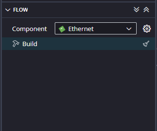
After successful creation of the platform, build the platform.
Step 15:
After building the platform go to Board Support Packages configuration of the newly created platform and add lwip220 library to the platform.
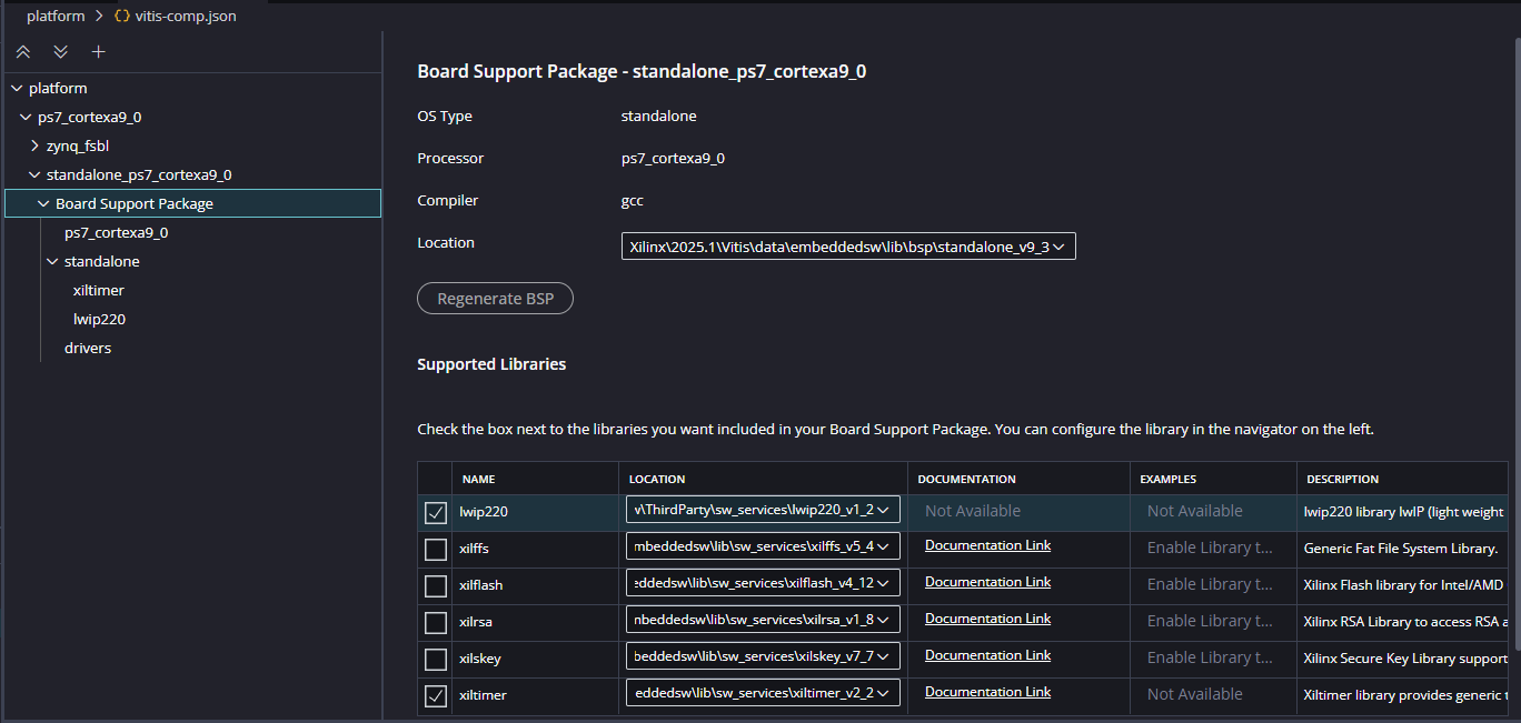
Step 16:
After adding the lwip220 to the platform , click on the lwip to configure the lwip library.
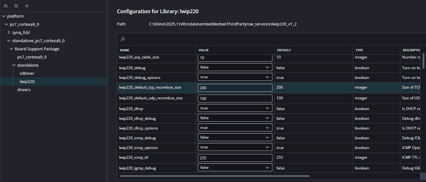
Initially, configure the platform to use Dynamic Host Configuration Protocol (DHCP). This is essential for adding the application. Set the following parameters to:
Initial Setup (DHCP)
lwip220_dhcp: True
lwip220_lwip_dhcp_does_acd_check: True
lwip220_pbuf_pool_size: 2048
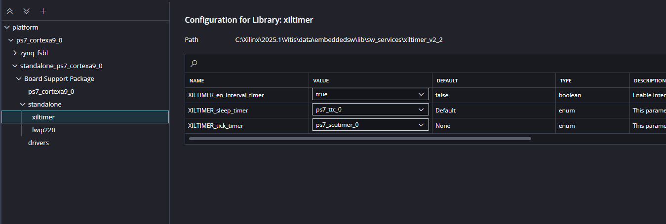
xiltimer: XILTIMER_en_interval_timer: True
Once these parameters are set, you can add the lwIP echo server application to the platform.
Make sure the configuration for xiltimer is same as below:
Step 17:
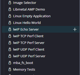
Next create the lwip echo server Application component by selecting the “IwIp Echo Server” template from the “examples”.
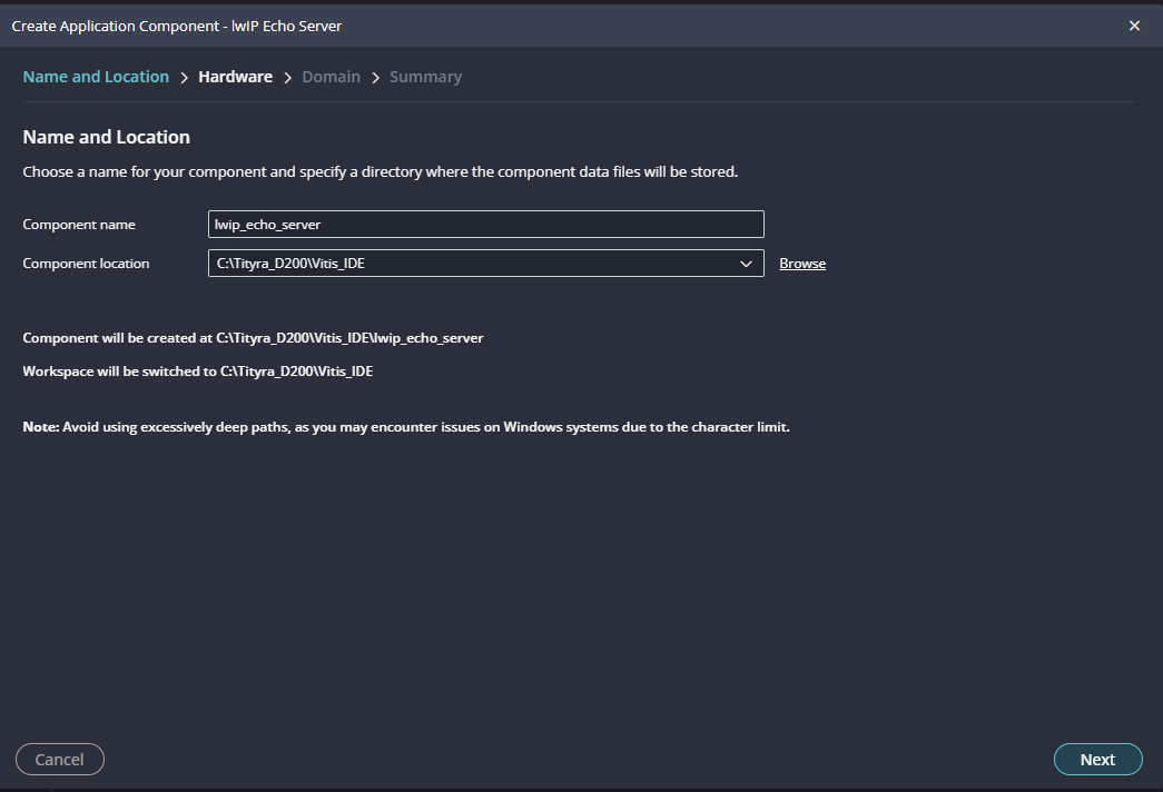
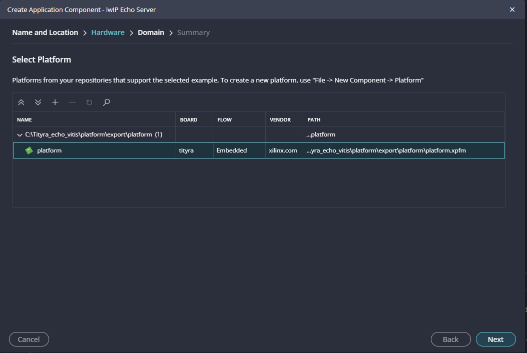
In “Create Application Component” tab specify project name and location, click “Next”.
Select newly created Platform and click “Next”.
When the lwip project is added successfully, build the project manually.
Static IP Configuration
After adding the application, if you want it to use a static IP address instead of DHCP, you must reconfigure the build. Set the following parameters to False:
lwip220_dhcplwip220_lwip_dhcp_does_acd_checklwip220_dhcp_optionsFinally, rebuild the application for the changes to take effect. This will allow the echo server to operate with a static IP.
Step 18:
Once the build is completed successfully, power up Tityra Core Z7 FPGA Development Board using USB type C cable and connect the JTAG cable for programming the device.
NOTE: Vitis does not include built-in support for KSZ Ethernet PHY drivers. To enable compatibility, the xemacpsif_physpeed.c file must be manually updated with the KSZ driver modifications. Replace the existing xemacpsif_physpeed.c file in your project with the provided file, which includes the necessary changes to support KSZ PHY drivers. This ensures proper Ethernet functionality in your application.
After modifying the xemacpsif_physpeed.c file , Build the project again.
Once the build is completed successfully, power up Tityra Core Z7 FPGA Development Board using USB type C cable and connect the JTAG cable for programming the device.
Step 19:
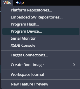
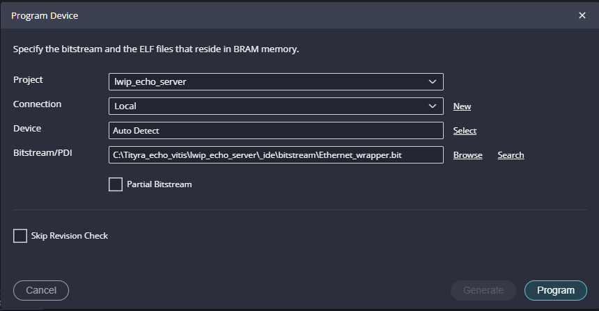
Program the FPGA on Tityra Core Z7 with a simple boot loop program by selecting the Program Device option from the Vitis menu.
Once the files are selected click on “Program” .
Step 20:
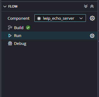
Meanwhile, open any serial terminal program (such as PuTTY, Teraterm etc) and open the port corresponding to Tityra Core Z7 with a 115200 baud rate (the default baud rate given in UART IP). Program the board by selecting the “Run”.
Step 21:
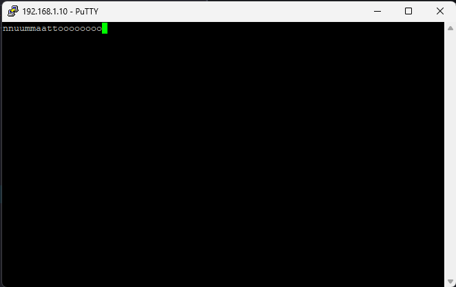
Observe the details displayed on the serial terminal.
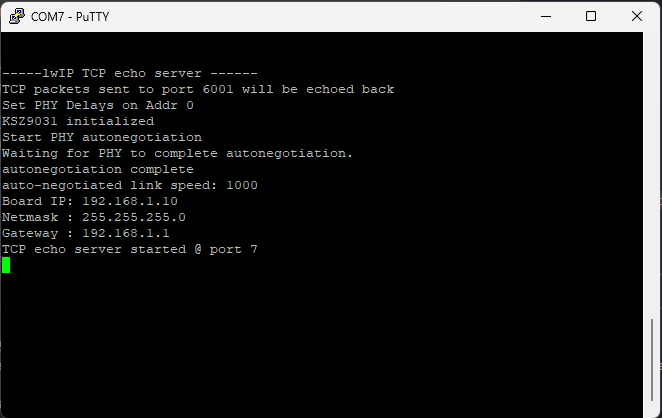
Step 22:
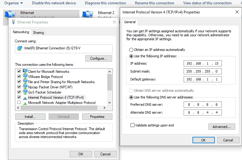
Connect the Ethernet cable to the board and the other end to the PC Ethernet port. Go to Control Panel. Go to Network and Internet -> Network and Sharing Centre -> Change adapter settings. Select “Change adapter settings”. Right-click on Ethernet, click properties, and select “IPv4”. Change the IPv4 address to 192.168.1.15 (any IP address can be used) and the default gateway to 192.168.1.1.
Step 23:
Open a telnet session with IP Address 192.168.1.10 (IP address as per main.c) at port 7, give input through the keyboard and observe the output. If you enter a character from the keyboard, you can observe the transmitted and echoed characters on telnet as shown.