Introduction
In this article we will use AMD Vitis unified to create a bootable image for TityraCore D200 for booting via following modes:
- SD Boot Mode
- QSPI Flash Boot Mode
TityraCore D200 Zynq Module can boot from JTAG as well. This is explained in detail in the article “Getting Started With Zynq on TityraCore Z7 using Vivado Design Suite“. SD Boot and QSPI Boot methods are available for booting TityraCore D200 from non-volatile sources . We will use Vivado to create a basic “Hello World” program for TityraCore D200 running on Zynq’s ARM processor and boot it from both SD Card as well as QSPI Flash.
Prerequisites
To follow this article, you would need the following:
- Hardware:
- TityraCore D200 SODIMM Module.
- TityraCore D200 carrier.
- AMD Platform Cable II JTAG debugger.
- SD card.
- Software:
- AMD Vivado Design Suite 2025.1
- Vitis Unified 2025.1
- FT_Prog tool for configuring on-board FT2232H USB Serial converter (download and install from FTDI website)
Let’s get started
The following steps will walk you through the process of creating a new project with Vivado and building a hardware platform with Zynq processing system using IP integrator. This article is written for Numato Lab’s TityraCore D200 SODIMM Module, but can be adapted to any other Zynq based platform with minor changes. Screenshots are added wherever possible to make the process easier to the reader.
Step 1:
Start Vivado Design Suite, and select “Create New Project” from Quick Start section. The project wizard will pop up. Press next to proceed with creating the project.
Step 2:
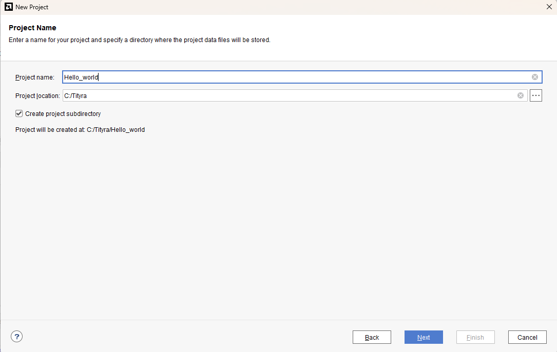
Type in a project name and save it at a convenient location. For this example “Hello_world” is used as project name, but feel free to use any name. Select the check box below to keep all project files in a single folder. The image below shows the settings for the example project. Click “Next” to continue.
Step 3:
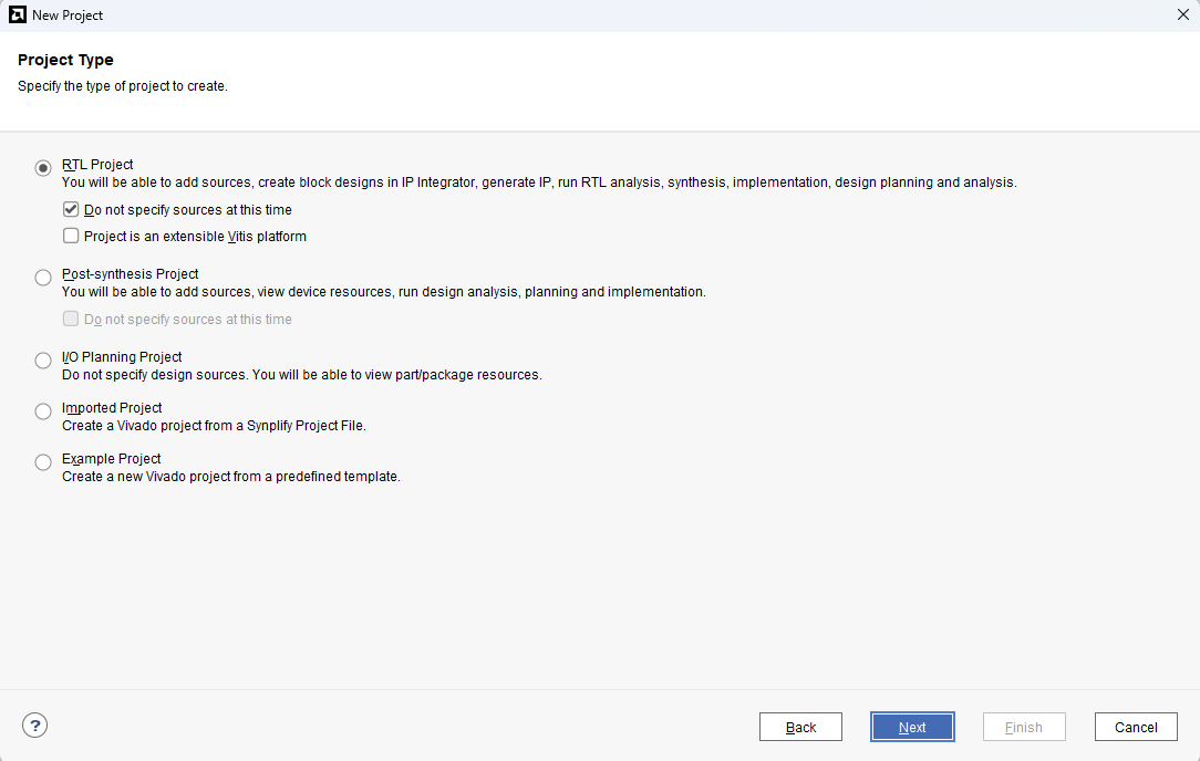
Choose “RTL Project” as project type and check the option “Do not specify sources at this time”.
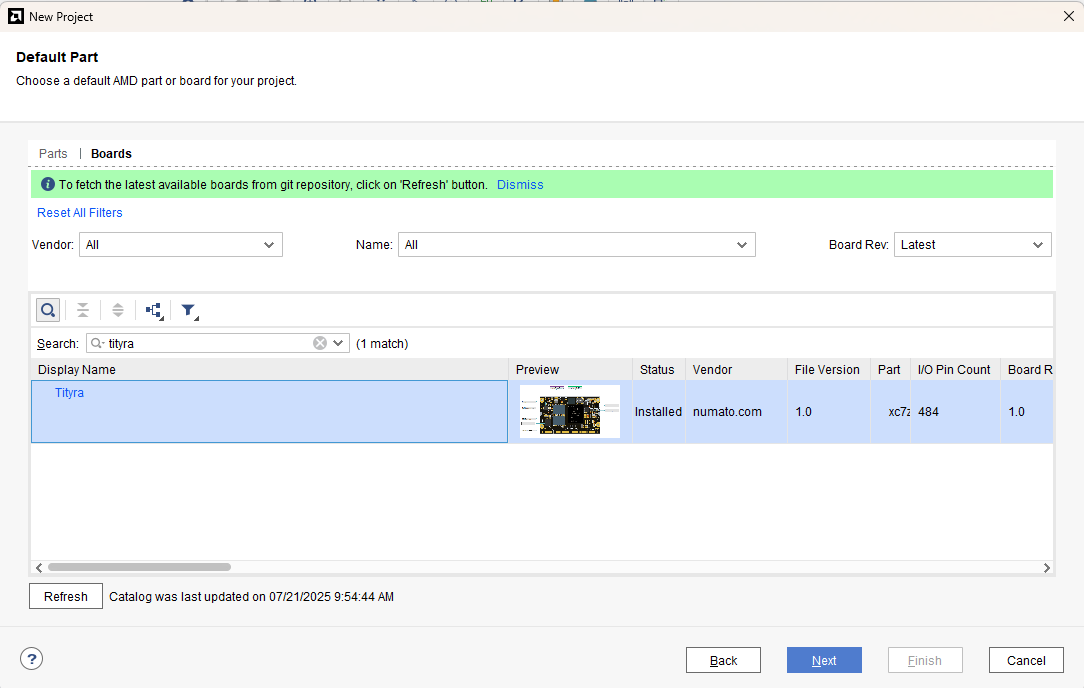
Step 4:
At the “Default Part” stage, switch to the “Boards” tab and set the vendor to numato.com. Select “Tityra” and click Next.If the Tityra board does not appear in the list, click “Refresh” to update the board catalog. Vivado will then download the latest board files, after which Tityra will become available for selection.
Continue the wizard and finish creating the project. When the new project wizard exits, a new project will be opened up in Vivado with the settings you have selected.
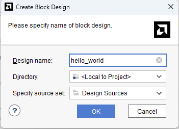
Step 5:
Under Flow Navigator, select “Create Block Design” in IP Integrator. Give an appropriate name to design. We will call it “hello_world” for example.
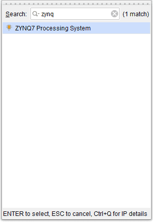
Step 6:
Go to Diagram window, right click and select “Add IP” from the popup menu. Search for ZYNQ7 Processing System. Add it to block design by double clicking.
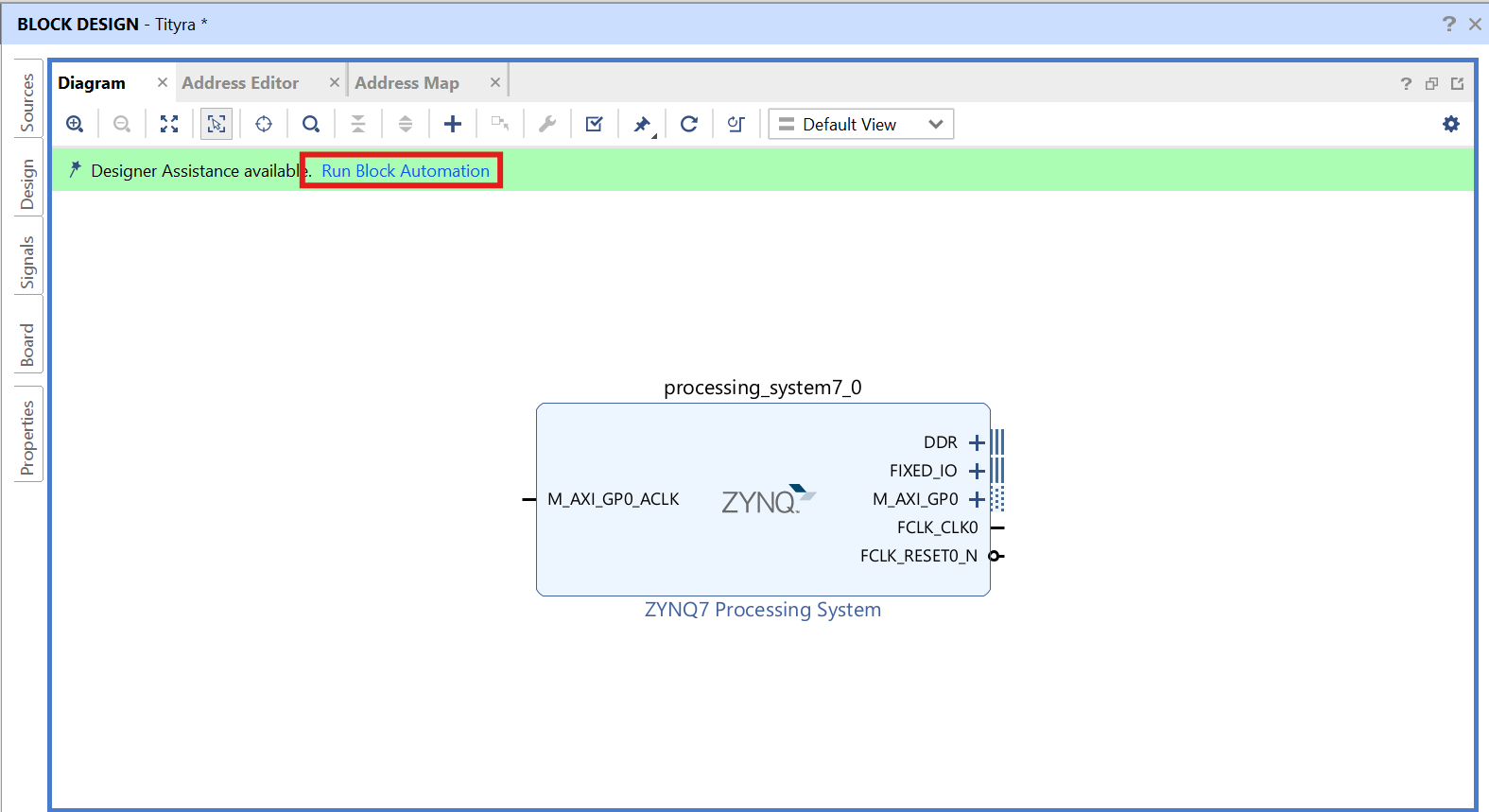
Step 7:
Click on “Run Block Automation” option on the green bar.
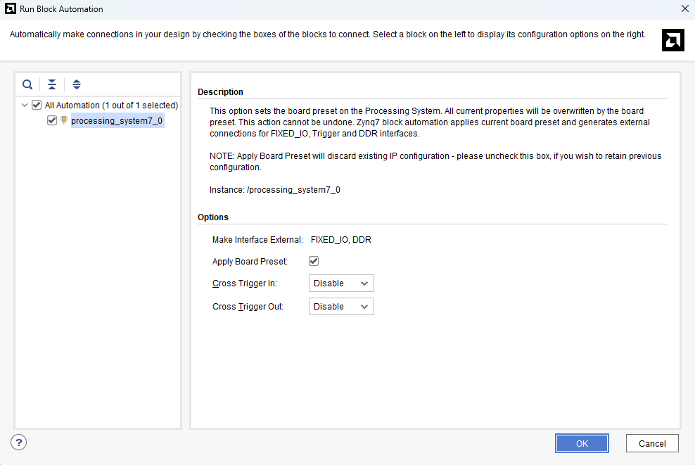
Step 8:
In the “Run Block Automation” window, select the options as in image below and click OK.
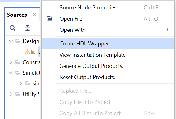
Step 9:
Go to “Sources” tab, right click on “hello_world” design file and select “Create HDL Wrapper”. Click OK on the window that appears to finish generating wrapper.
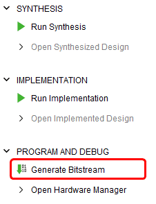
Step 10:
Click “Generate Bitstream” under PROGRAM AND DEBUG section and click “Yes” in any subsequent dialog window which comes up.
Step 11:
Once the bitstream is successfully generated, close any “Bitstream Generation Completed” dialog which comes up asking for what to do next , click OK.
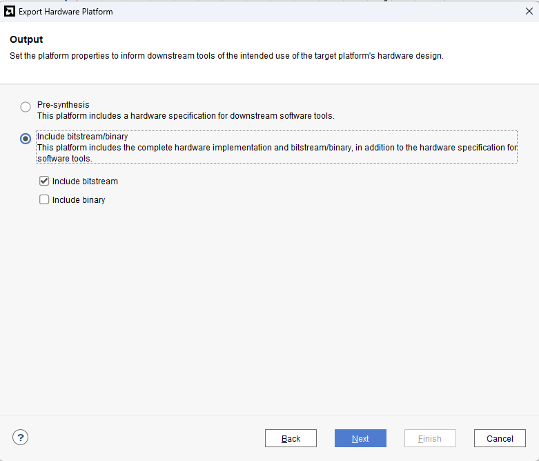
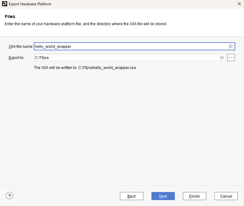
Go to File -> Export -> Export Hardware…
Check “Include bitstream”, keep “Export to:” default, and click OK.
Step 12:
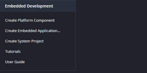
Launch Vitis IDE and create a new platform for the project, by selecting “Create Platform Component”, click “Next”, in the Flow tab select the XSA file saved using the step 15 and finally click “Next” and “Finish” respectively.
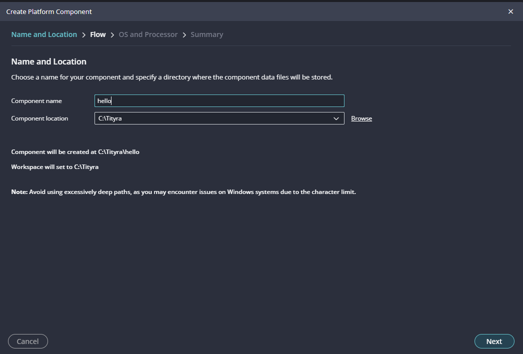
Step 13:
Give the component name and the platform location and click on “Next”.
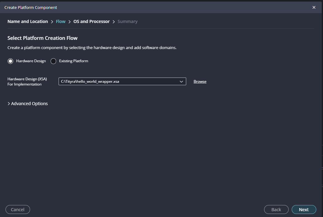
Step 14:
In the next tab browse the XSA file , select it , click on “Next”. In the next OS and Processor tab click “Next” and “Finish”.
After successful creation of the platform, build the platform.
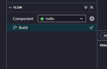
After successful creation of the platform, build the platform.
Step 15:
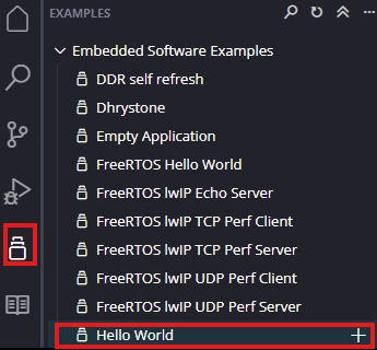
Next create the Hello world Application component by selecting the “Hello world” template from the “examples”.
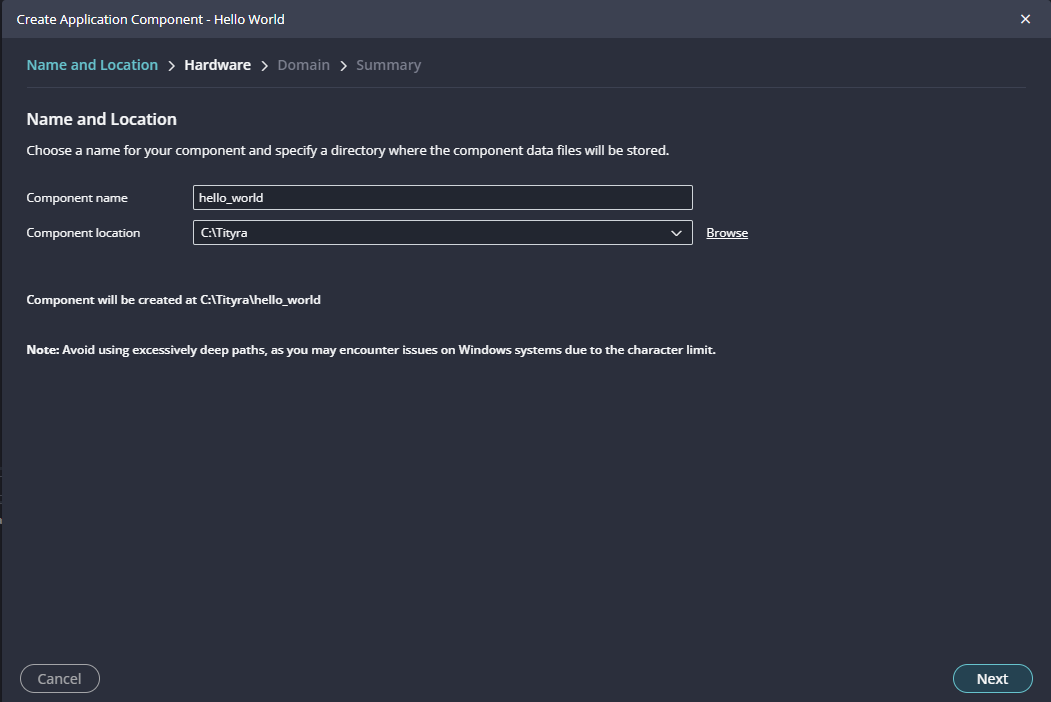
In “Create Application Component” tab specify project name and location, click “Next”.
Select newly created Platform and click “Next”.
There is a minor modification we need to do to the code at this point. The application generated using vitis will print “Hello World” a single time and exit. We want to change the application code so that the code will keep printing the data indefinitely. Find the printf statement in the code (helloworld.c) and replace that with the following code.
while(1)
{
       print("Hello World\n\r");
}
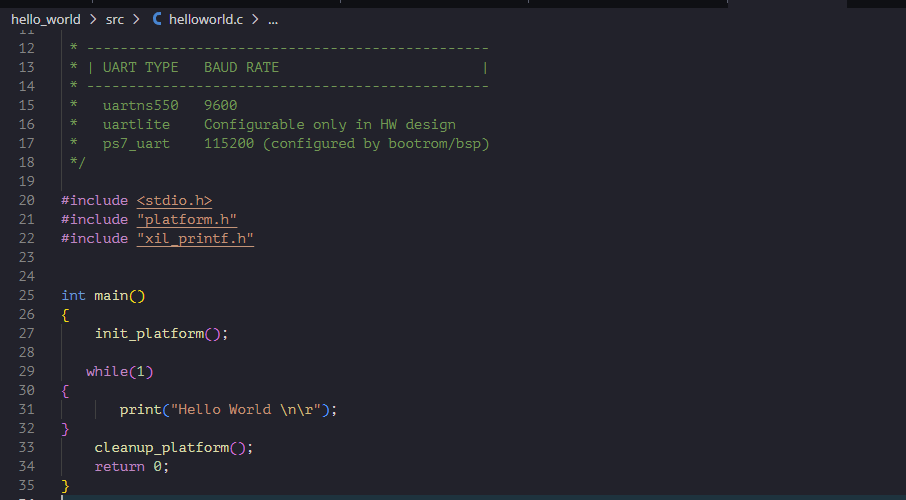
All that we are doing here is to surround the printf statement in a while loop so the printing never stops. Save the project and build.
When the Helloworld project is added successfully, build the project manually.
Step 16:
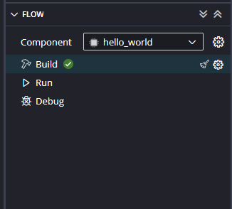
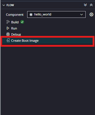
Select the ‘hello_world’ in the Project Explorer, After selecting the hello world select “Create Boot image” in the Flow navigator.
The tool automatically picks the files needed to create bootable image. If the files are not added automatically then add the following files manually.
- fsbl.elf (Bootloader)
- Hello_word.bit (datafile)
- hello_World.elf (datafile)
Next give the desired name location of the .bif and .bin files to be saved in the Boot Image Options in bottom.
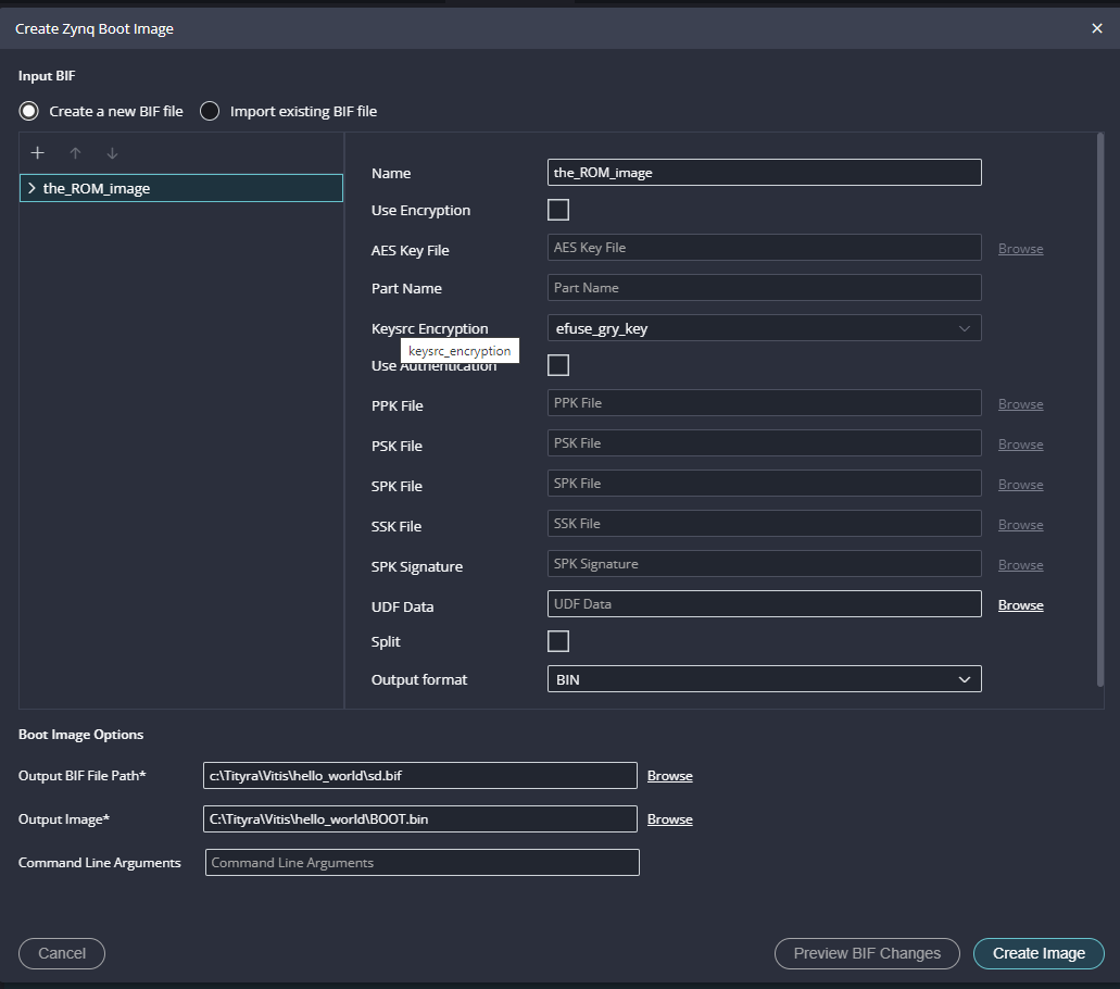
Step 17:
To boot from SD card we need a .bin file, so, select the output format as ‘BIN’ if not already selected. Click on “Create Image” to create BOOT.bin file.
Step 18:
After generating BOOT.bin file successfully, copy the BOOT.bin into SD card. Make sure to configure channel B of the onboard FT2232H USB – Serial device as virtual communication port using FT_Prog. The process is very similar to that of Saturn and details are available here. Change the Tityra boot mode to SD Card by following instructions in the TityraCore D200 User Manual. Insert the SD card into Tityra and connect the Type C USB cable. Power up the board.
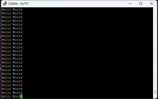
Open any serial terminal (such as PuTTY) and connect to the COM Port corresponding to Tityra at 115200 baudrate. If everything went well, Tityra should boot up from SD card and print “Hello World” repeatedly over USB-UART on the serial terminal application.

Booting from QSPI Flash
Step 1:
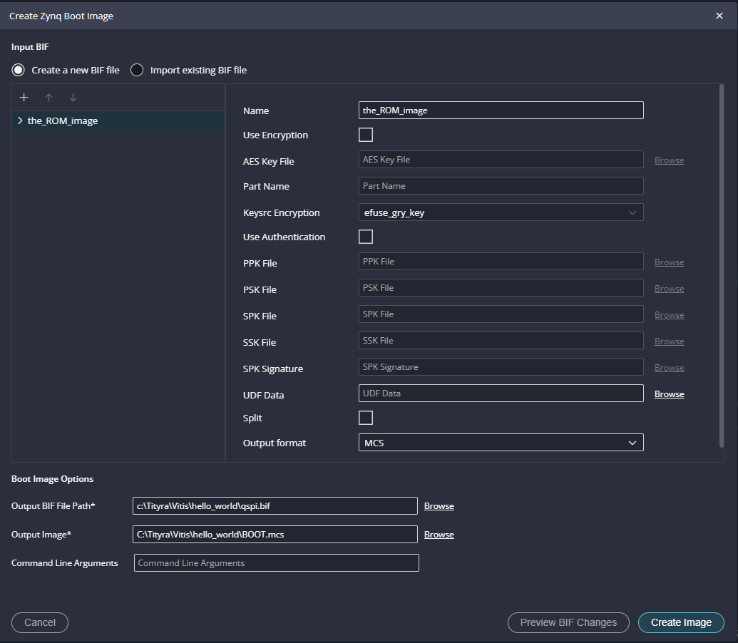
Follow the same steps from 1 to 6 mentioned in the Boot from SD card. To boot from QSPI Flash we need .mcs file so, select output format as MCS if not already selected. Click on “Create Image” to create BOOT.mcs file.
Step 2:
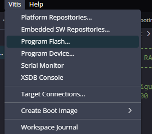
After BOOT.mcs file is generated, make sure to configure channel B of the onboard FT2232H USB – Serial device as virtual communication port using FT_Prog. The process is very similar to that of Saturn and details are available here. Then, change the Tityra boot mode to QSPI Flash Boot Mode by following instructions in the TityraCore D200 User Manual. Connect the Type C USB cable and AMD Platform Cable USB II to TityraCore D200 and then power up the board. Program the flash memory by selecting BOOT.mcs image file in the vitis -> Program Flash.
Open any serial terminal (such as PuTTY) and connect to the COM Port corresponding to Tityra at 115200 baudrate. If everything went well, Tityra should boot up from QSPI flash and print “Hello World” continuously over USB-UART on the serial terminal application.