Introduction
In this article we will use AMD Vitis IDE to create a bootable image for Styx Z7 FPGA Module for booting via following modes:
- SD Boot Mode
- QSPI Flash Boot Mode
Styx Zynq Module can boot from JTAG as well. This is explained in detail in the article “Getting Started With Zynq on Styx using Vivado Design Suite“. SD Boot and QSPI Boot methods are available for booting Styx Z7 FPGA Module from non-volatile sources . We will use Vivado to create a basic “Hello World” program for Styx Z7 FPGA Module running on Zynq’s ARM processor and boot it from both SD Card as well as QSPI Flash.
Prerequisites
- Hardware:
- Styx Z7 FPGA Module
- AMD Platform Cable II JTAG debugger.
- Software:
- Vivado Design Suite 2025.1
- Vitis unified IDE 2025.1
Lets get started
The following steps will walk you through the process of creating bootable image. To create Vivado project, follow the same steps from 1 to 14 mentioned in the Getting Started with Zynq Styx article here
After creating the xsa file successfully, we now move on to creating the bootable image for SD card and QSPI Flash on Vitis IDE.
Booting from SD card
Step 1:
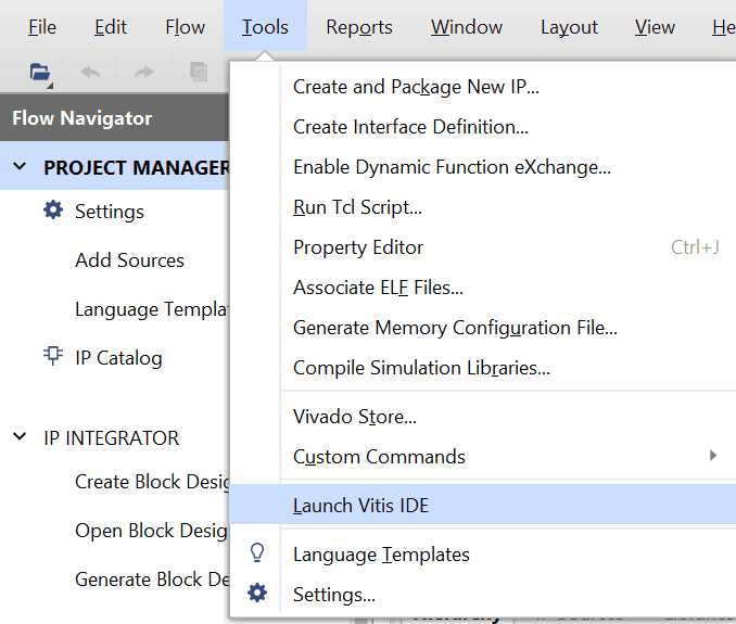
Finally open Vitis unified IDE by following the steps Tools–> Launch Vitis IDE .
Step 2:
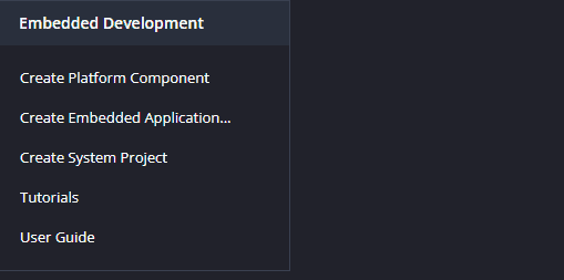
Select Launch Vitis IDE and Create a new platform for the project, by selecting “Create Platform Component”.
Step 3:
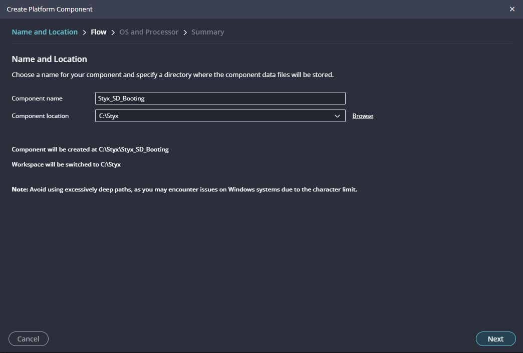
Give the component name and the platform location and click on “Next”. For the XSA file choose the hello_wrapper.xsa.
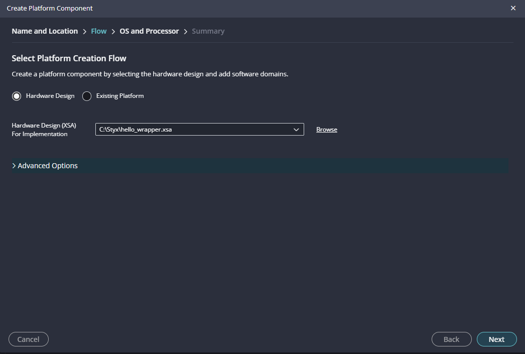
After successful creation of the platform, build the platform.
Step 4:
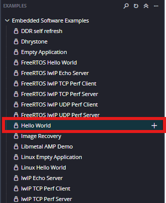
The next step is to create a ‘Hello World’ application in the same way as fsbl application project. By selecting the “Hello World ” template from the “examples”, select “Create Application Component from Template”, specify project name and location, click “Next”, select newly created platform, click “Next” and then finally “Finish”.
There is a minor modification we need to do to the code at this point. The application generated using vitis will print “Hello World” a single time and exit. We want to change the application code so that the code will keep printing the data indefinitely. Find the printf statement in the code (helloworld.c) and replace that with the following code.
while(1){print("Hello World\n\r");}
After editing , the code should look like this: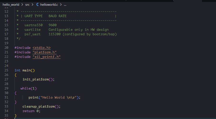
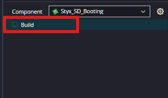
All that we are doing here is to surround the printf statement in a while loop so the printing never stops. Save the project and build.
Step 5:
Select the ‘helloWorld’ in the Project Explorer, After selecting the hello world select “Create Boot image” in the Flow navigator.
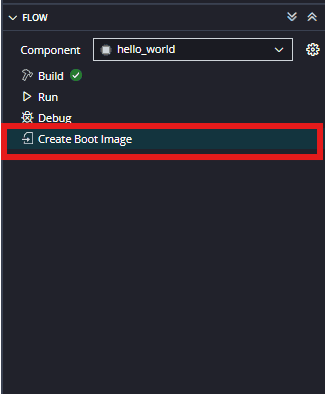
The tool automatically picks the files needed to create bootable image. If the files are not added automatically then add the following files manually.
- fsbl.elf (Bootloader)
- Hello_word.bit (datafile)
- hello_World.elf (datafile)
Next give the desired name location of the .bif and .bin files to be saved in the Boot Image Options in bottom.
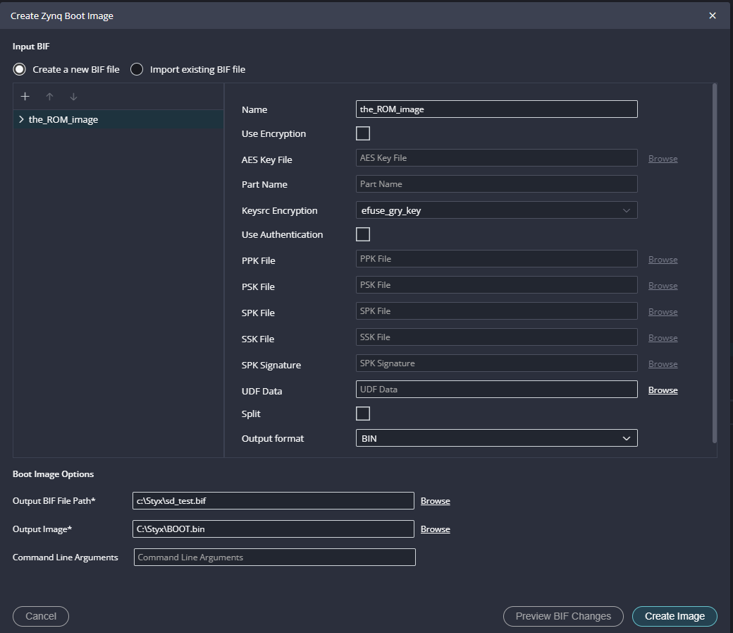
Step 6:
To boot from SD card we need a .bin file, so, select the output format as ‘BIN’ if not already selected. Click on “Create Image” to create BOOT.bin file.
Step 7:
After generating BOOT.bin file successfully, copy the BOOT.bin into SD card. Make sure to configure channel B of the onboard FT2232H USB – Serial device as virtual communication port using FT_Prog. The process is very similar to that of Saturn and details are available here. Change the Styx boot mode to SD Card by following instructions in the Styx User Manual. Insert the SD card into Styx and connect the micro USB cable. Power up the board.

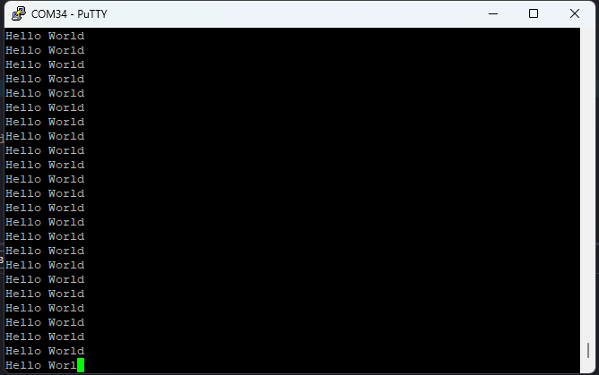
Open any serial terminal (such as PuTTY) and connect to the COM Port corresponding to Styx at 115200 baudrate. If everything went well, Styx should boot up from SD card and print “Hello World” repeatedly over USB-UART on the serial terminal application.
Booting from QSPI Flash
Step 1:
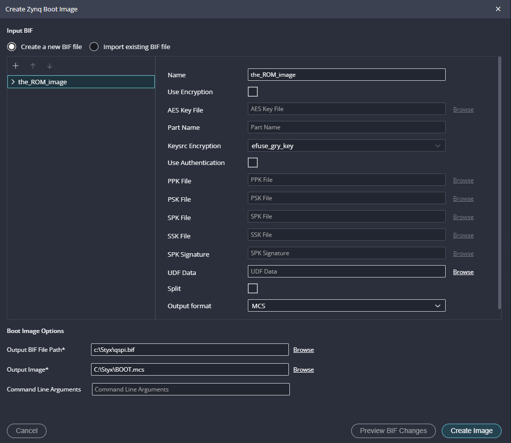
Follow the same steps from 1 to 6 mentioned in the Boot from SD card. To boot from QSPI Flash we need .mcs file so, select output format as MCS if not already selected. Click on “Create Image” to create BOOT.mcs file.
Step 2:
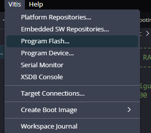
After BOOT.mcs file is generated, make sure to configure channel B of the onboard FT2232H USB – Serial device as virtual communication port using FT_Prog. The process is very similar to that of Saturn and details are available here. Then, change the Styx boot mode to QSPI Flash Boot Mode by following instructions in the Styx User Manual. Connect the micro USB cable and AMD Platform Cable USB II to Styx and then power up the board. Program the flash memory by selecting BOOT.mcs image file in the Vitis-> Program Flash.
Open any serial terminal (such as PuTTY) and connect to the COM Port corresponding to Styx at 115200 baudrate. If everything went well, Styx should boot up from QSPI flash and print “Hello World” continuously over USB-UART on the serial terminal application.