Introduction:
High-speed serial transceivers are a critical part of modern FPGA designs, enabling data transfer at multi-gigabit rates for applications such as networking, data acquisition, and high-performance computing. These transceivers operate at very high frequencies and are highly sensitive to clocking, signal integrity, and board routing. Because of this, validating every high-speed lane on a new FPGA board is an essential step before using it in real protocols and designs.
AMD provides the IBERT (Integrated Bit Error Ratio Tester) IP core as a built-in tool for testing and characterizing these high-speed transceivers. IBERT allows users to generate test patterns, monitor bit error rates, check PLL lock status, and analyze link quality without needing any external protocol logic. It is commonly used during board bring-up to confirm that the transceiver hardware, reference clocks, and signal paths are working correctly.
In this article, the focus is on performing external loopback testing using IBERT across all GTH transceiver banks on the FPGA Neutron KU60 board. In external loopback mode, the transmitted high-speed data is routed out of the FPGA through the board traces and connectors and then physically looped back into the receiver. By running these tests across all banks, we ensure that every GTH lane on the board is functional and ready for high-speed communication.
Prerequisites
- Hardware:
- The Neutron KU60 FPGA Development Board
- USB C-type cable
- AMD Platform Cable USB or NLJTPRG002 (optional)
- 12V DC Power Supply (max 5A current rating)
- FMC HPC Test Jig
- FMC+ HSPC Test Jig
- M.2 loopback module
- SFP+ module with loopback cable
- SMA MMCX cables
- Software:
- AMD Vivado Design Suite 2024.1
Let’s get started
Step 1:
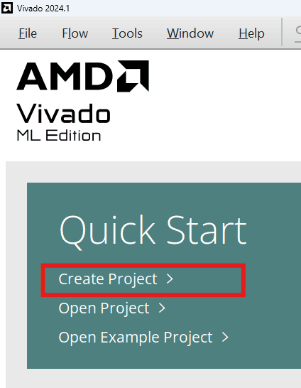
Start Vivado Design Suite, and select “Create New Project” from the Quick Start section. The project wizard will pop up. Press Next to proceed with creating the project.
Step 2:
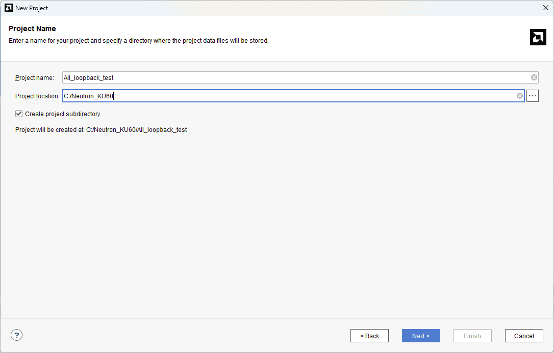
Type in a project name and save it at a convenient location. For this example, “All_loopback_test” is used as the project name, but feel free to use any name. Select the check box below to keep all project files in a single folder. The image below shows the settings for the example project. Click “Next” to continue.
Step 3:
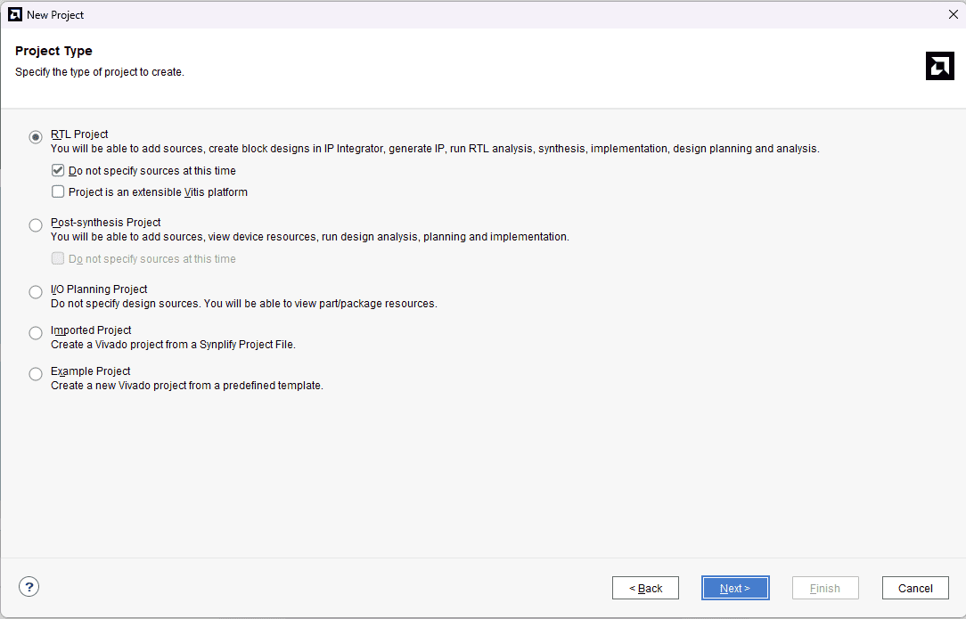
Choose “RTL Project” as project type and check the option “Do not specify sources at this time”.
Step 4:
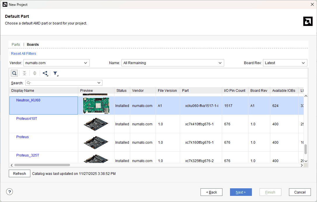
At the “Default Part” stage, switch to the “Boards” tab and set the vendor to numato.com. Select “Neutron_KU60” and click Next. If the Neutron_KU60 does not appear in the list, click “Refresh” to update the board catalog. Vivado will then download the latest board files, after which Neutron_KU60 will become available for selection.
Continue the wizard and finish creating the project. When the new project wizard exits, a new project will be opened up in Vivado with the settings you have selected.
Step 5:
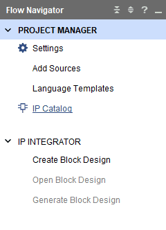
Under Flow Navigator, select “IP Catalog”.
Step 6:
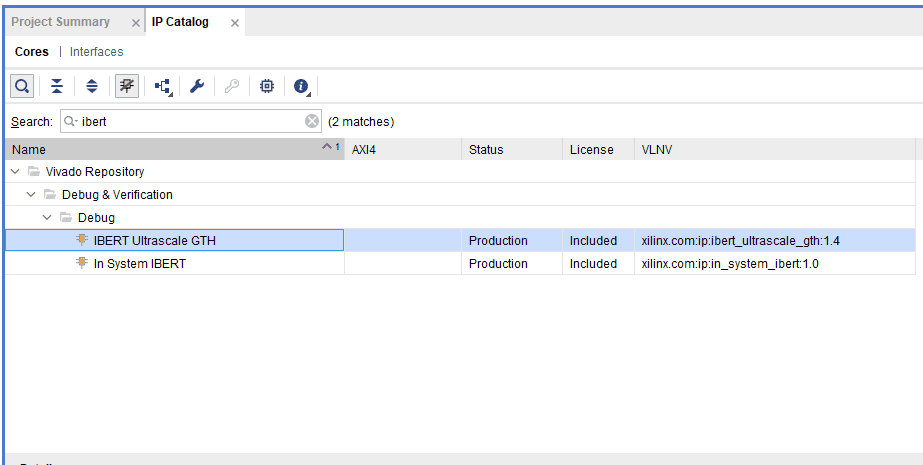
Search “IBERT” in the IP Catalog and double-click on the IBERT Ultrascale GTH to customize it.
Step 7:
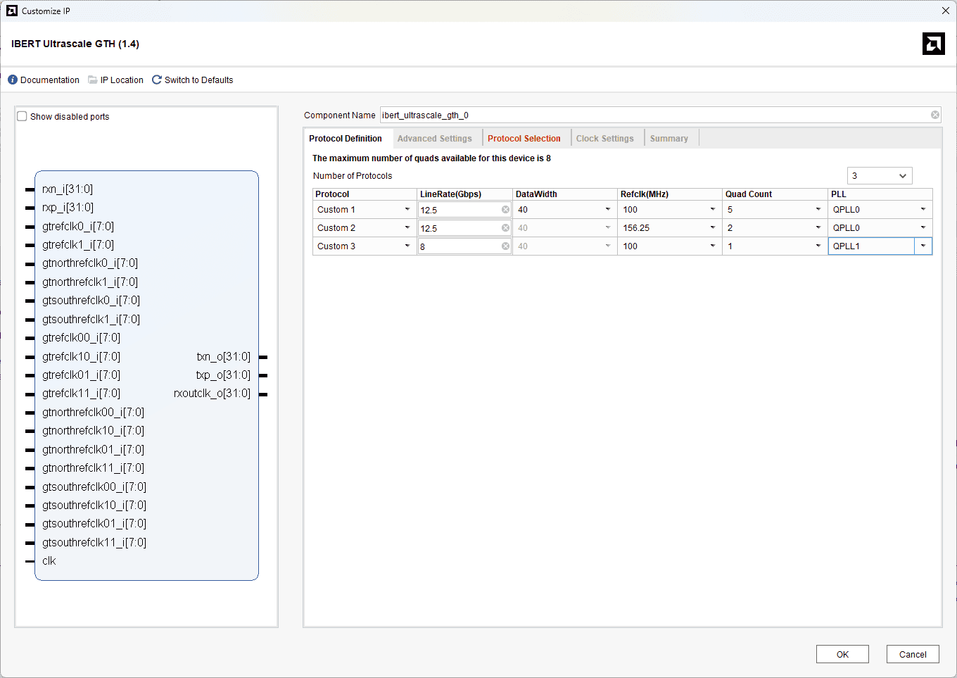
We will be selecting all available GTH transceiver banks on the Neutron KU60 to ensure complete coverage of the high-speed resources on the board. The appropriate reference clock sources for each bank will be configured according to the board design, and the line rate will be set based on the intended test speed. Follow the images below for the customization.
Change the “Number of Protocols” to 3.
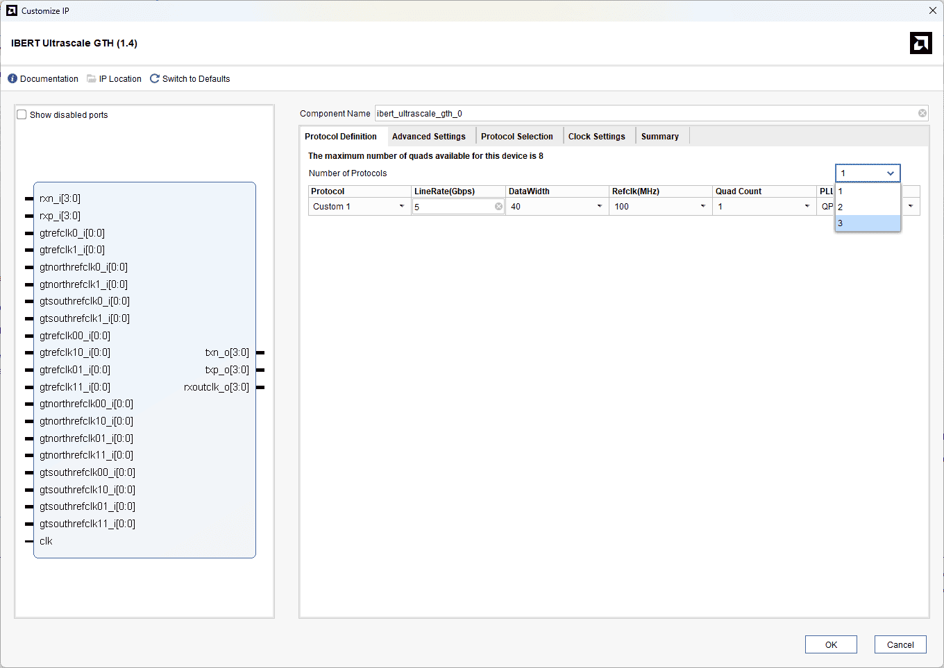
Change the LineRate (Gbps) to 12.5 for Custom 1 & 2 and 8 for Custom 3. Change the Refclk(MHz), Quad Count, and PLL according to the image below.
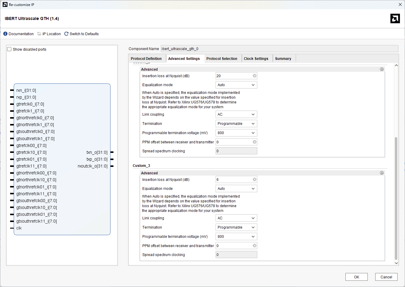
In Advance settings tab, under Custom_3, change the Insertion loss at Nyquist (dB) to 6 (because of using optic fibre cables for SFP+).
In the protocol selection tab, choose the “protocol Selected” and “Refclk Selection” as shown in the image below

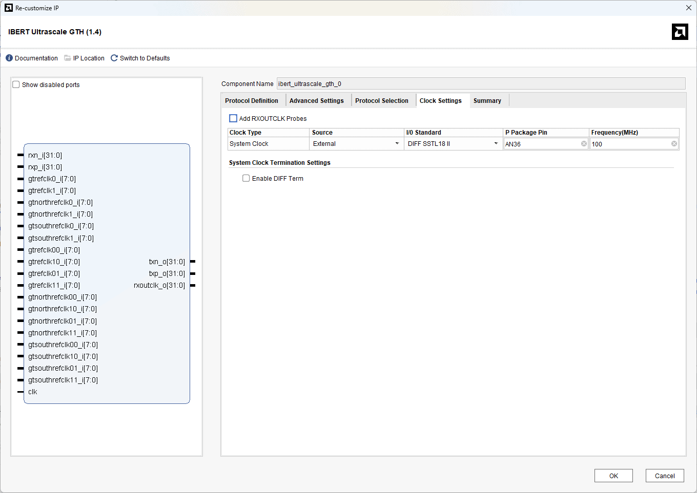
Select the “Source” as External and give the correct pin as shown below
Click OK to Customize the IP, and click on “Generate” to generate an IP.
Step 8:
In the Source tab, right-click on the design and click on “Open IP Example Design”. And click Ok.
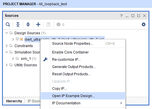
Once the IP example design is opened, Vivado will launch a new project window containing the generated reference design for the IBERT core. In this newly opened Vivado instance, proceed to generate the bitstream for the example design. This bitstream will be used to program the FPGA and begin the external loopback testing of the GTH transceiver banks.
Step 9:
After the bitstream is generated successfully, power up the Neutron KU60 FPGA Development Board using the 12V DC power supply and connect the JTAG cable or the USB Cable for programming the device.
Before programming the FPGA, ensure that all required modules connected to the GTH transceiver banks are properly connected on the board, including the FMC HPC, FMC+ HSPC, SFP+ module with loopback cables, MMCX cables for high-speed signal connections, and the M.2 loopback module inserted into the M.2 slot.
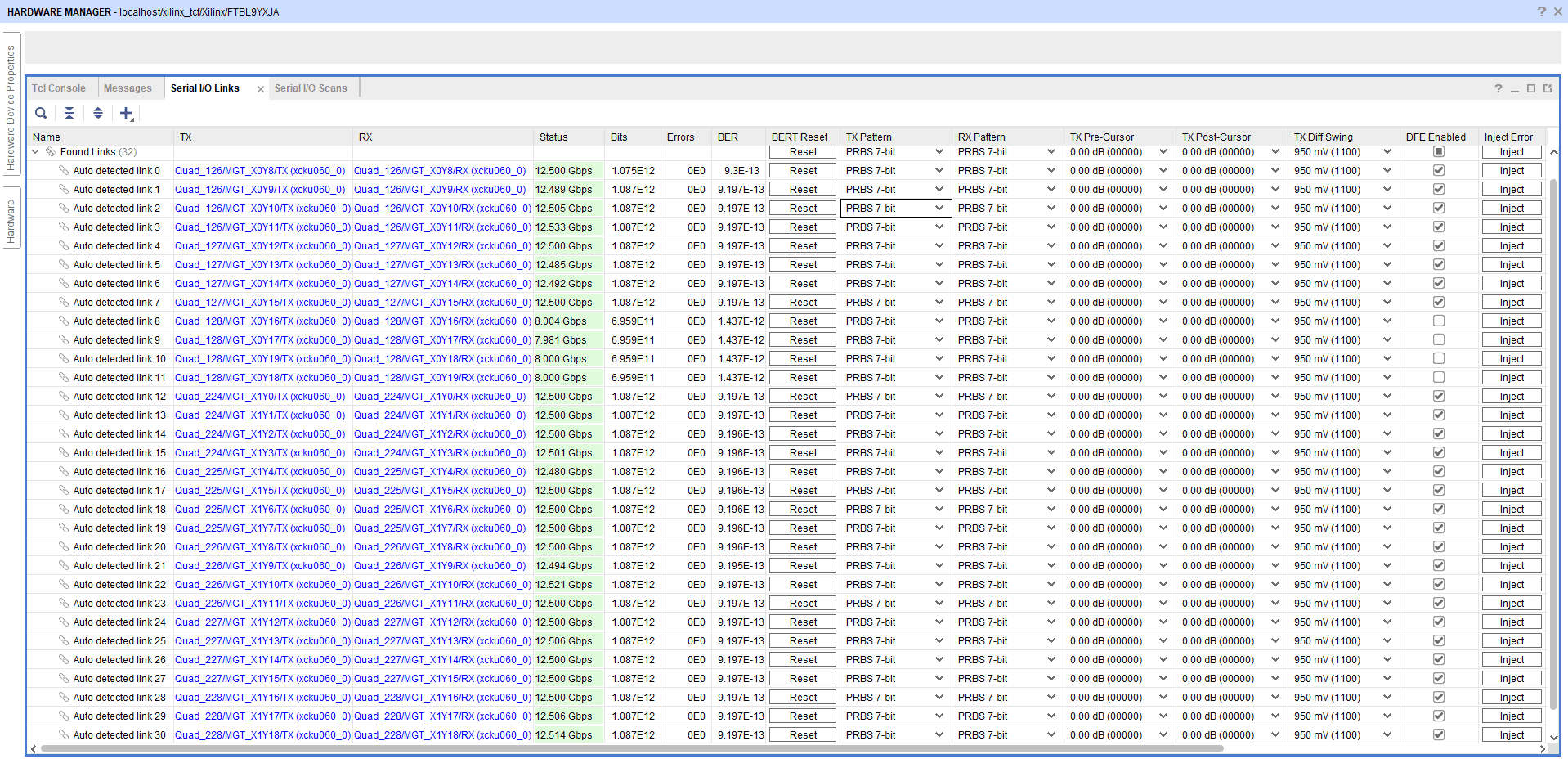
Step 10:
After programming the bitstream, click on “Auto Detect IO links.” Will be able to see the output as shown below.