In this project, we will showcase the process of implementing a basic “Hello World” project on the Eagle Core PolarFire SoC System on Module (SoM). Within the PolarFire SoC, there are five RISC-V cores in total. Among them, one E51 core serves as the monitor core, while the remaining four U54 cores are responsible for executing applications. For this project, we will use a single core to display the “Hello World” message, and we will monitor the output using a serial terminal (PuTTy) utilizing UART communication.
Prerequisites:
Hardware:
- EagleCore PolarFire SoC SOM
- FlashPro 6/5 programmer
- USB A to USB Type C cable
Software:
- MSS Configurator
- Libero SoC
- Softconsole
Implementation:
PolarFire SoC MSS Configurator
Libero makes use of an external application called the PolarFire SoC MSS Configurator to generate and set up the Microcontroller Subsystem (MSS) for the PolarFire SoC. Afterward, this configured component is integrated into the SmartDesign.
Step 1:
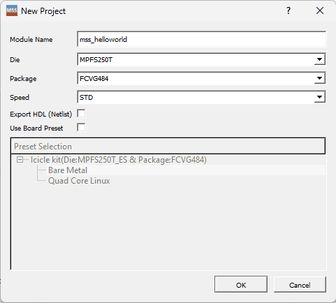
Open the PolarFire SoC MSS Configurator application. Once the application has launched, you should create a new project and give the appropriate name for the Configurator.
Step 2:
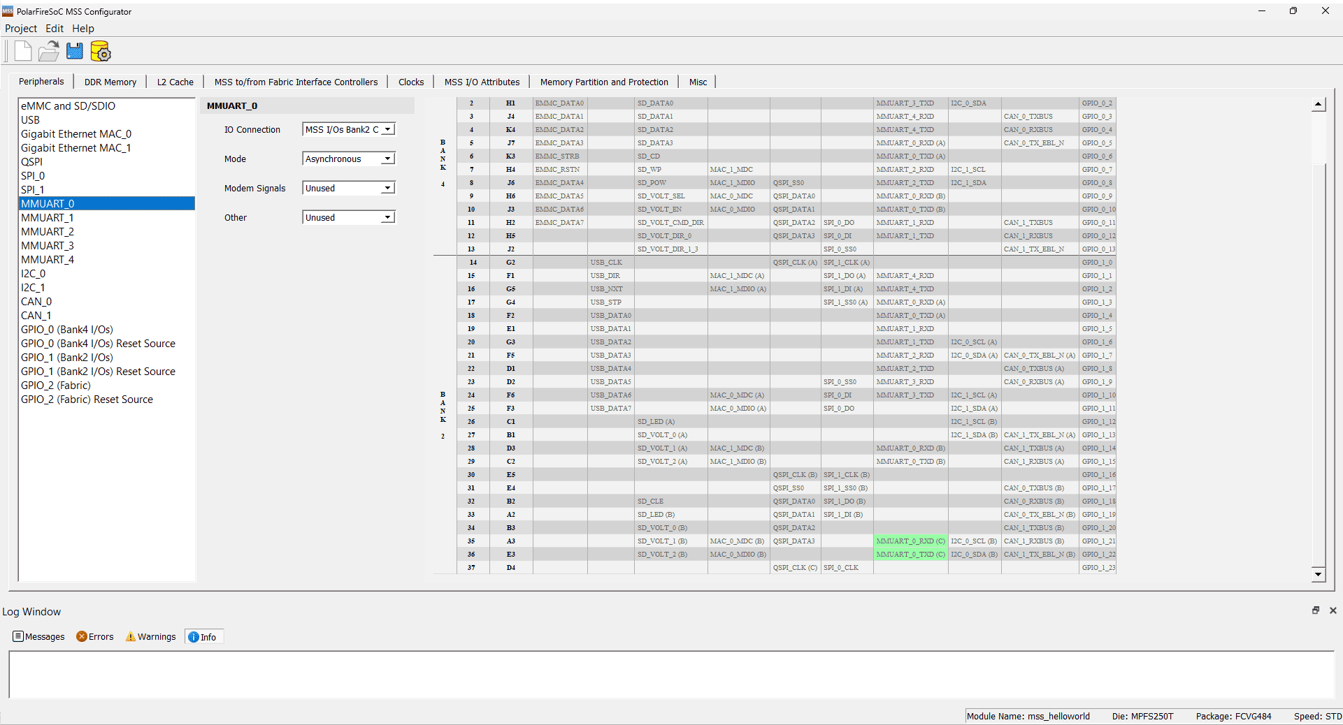
Navigate to the “Peripheral” tab and choose “MMUART_0” Configure its settings according to the provided image below.
Step 3:
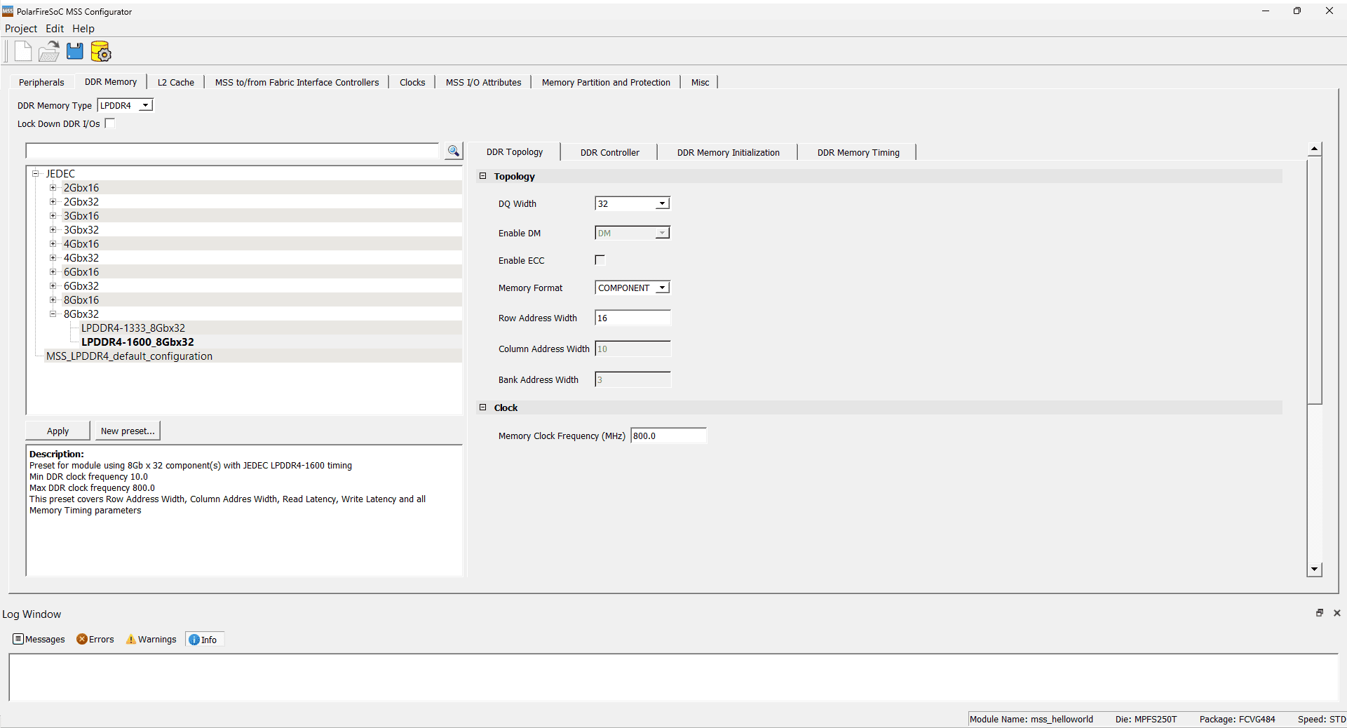
Now, under the “DDR Memory” tab, select “LPDDR4” as the “DDR Memory Type.” Choose “LPDDR4-1600_8Gbx32” as the JEDEC Configuration. Please maintain the default values for the “DDR Topology,” “DDR Controller,” “DDR Memory Initialization,” and “DDR Memory Timing” tabs.
Step 4:
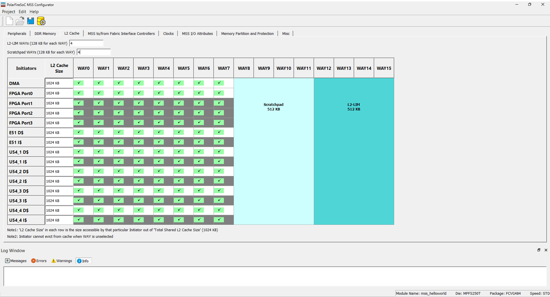
Now, under the “L2 Cache” tab, set L2-LIM WAYs to 4 and Scratchpad WAYs to 4.
Step 5:
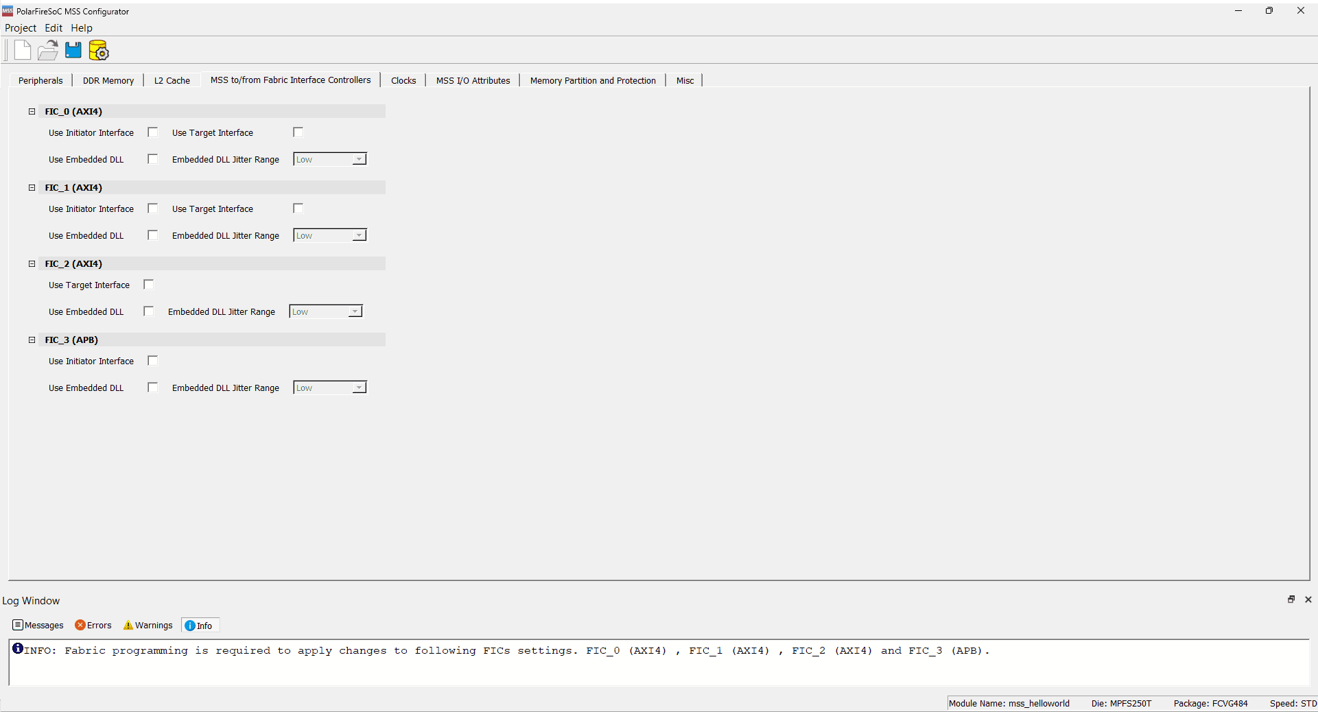
Disable all of the FIC interface under the MSS to/from fabric Interface Controller Tab.
Step 6:
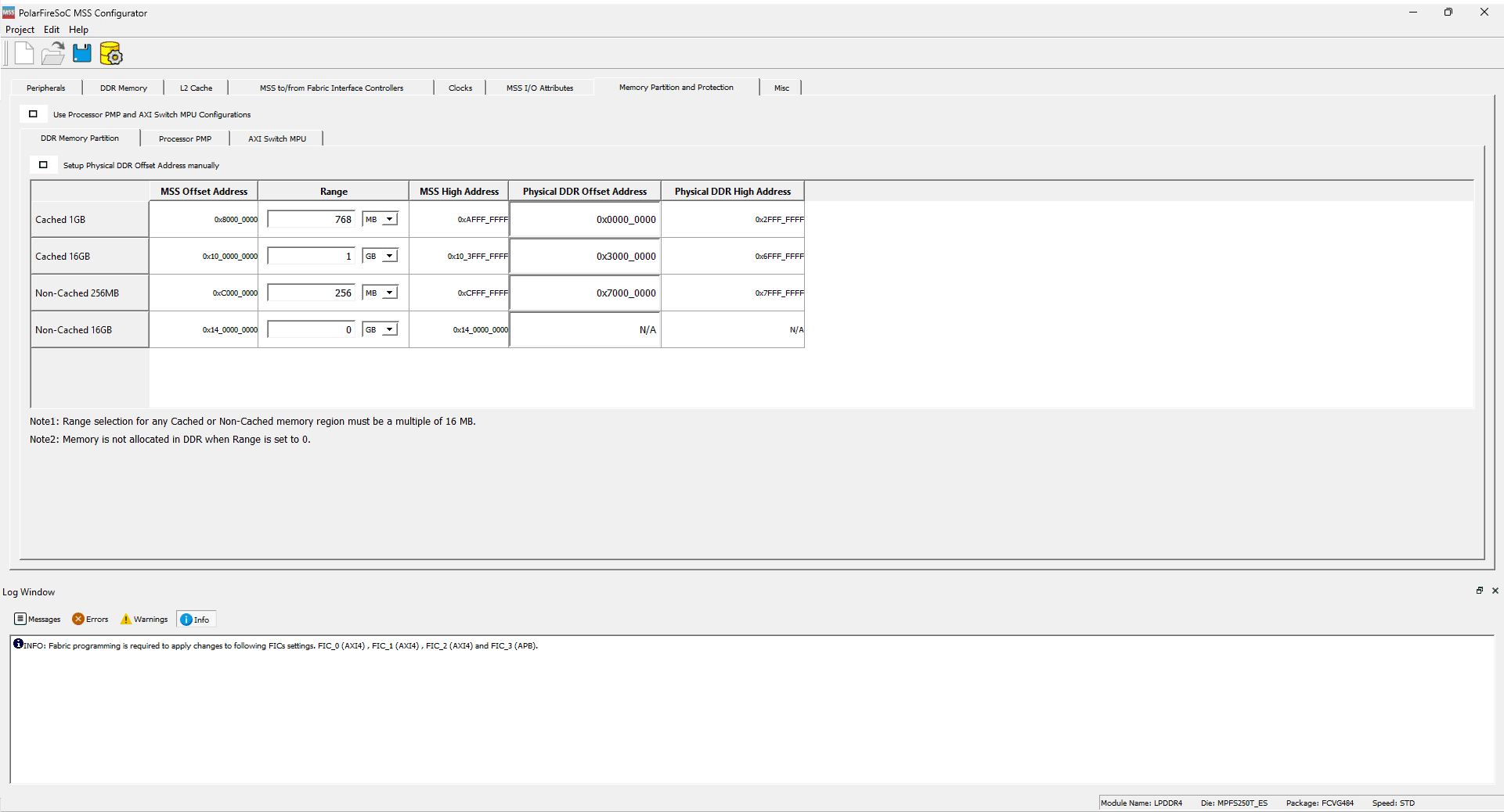
Now under the Memory Partition and Protection tab, give the Cached 16GB Range value as 1GB
Step 7:
Now generate the output but click on the ![]() Icon or Project -> Generate. Provide a suitable location where the files should be saved.
Icon or Project -> Generate. Provide a suitable location where the files should be saved.
Files included:
- mss_helloworld.cfg
- mss_helloworld.cxz
- mss_helloworld_mss_cfg.xml
- mss_helloworld_Report.html
Libero SoC
Step 8:
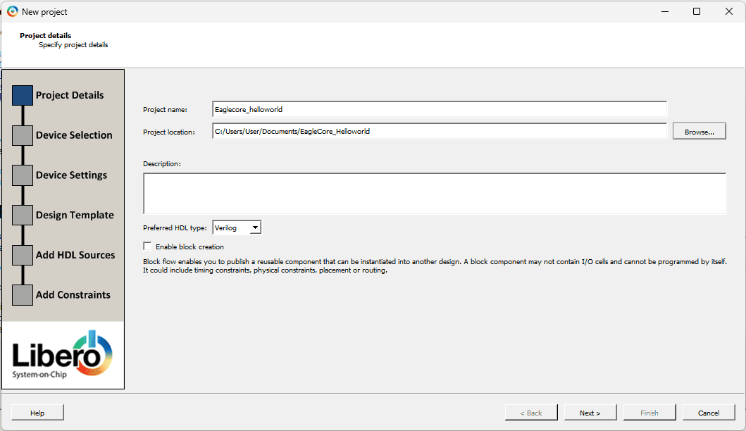
Open Libero SoC, then create a new project by clicking on “Project” > “New Project.” Given the Project name and Project location Click Next.
Step 9:
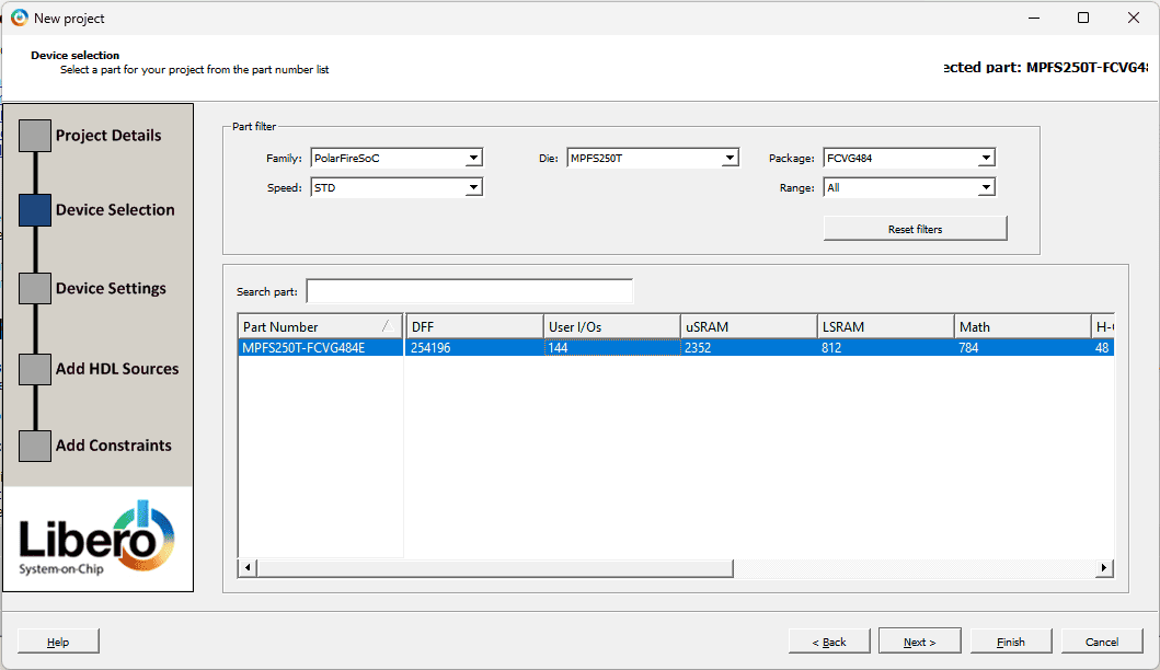
In the “Device selection” window, choose the correct part number( MPFS250T_FCVG484) as provided below. Click Next.
Step 10:
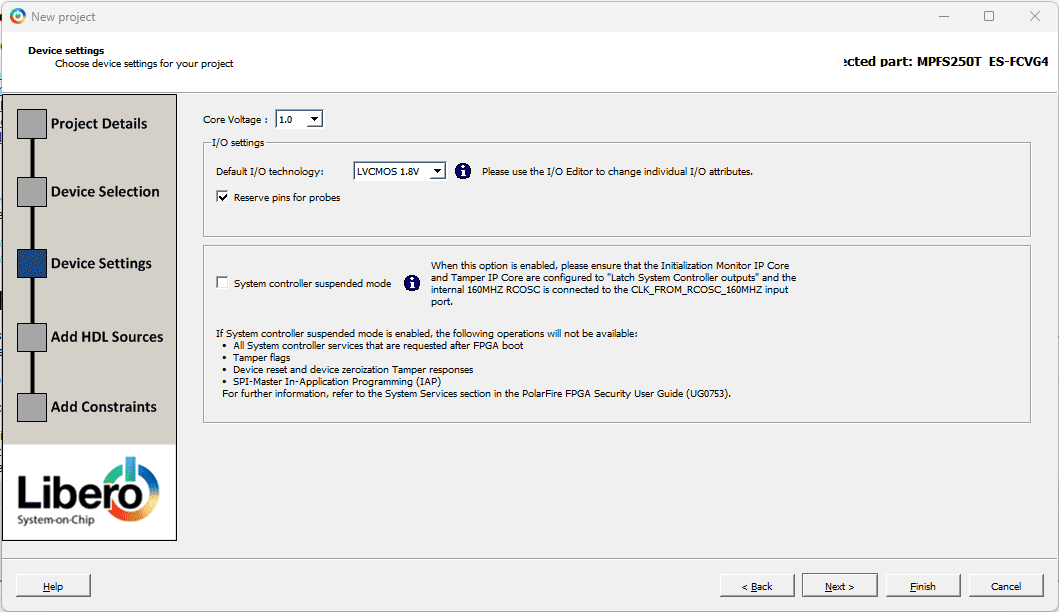
In the Device setting window select the Core Voltage as 1.0V and Default I/O Technology as LVCMOS 1.8V. Click Next.
As there’s no need to include HDL source or Constraint files directly, proceed by clicking Finish.
Step 11:
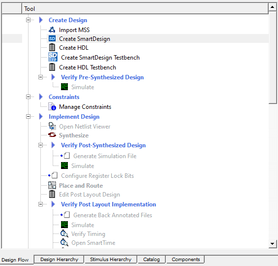
Once the New Project Wizard opens, double-click on the Create SmartDesign (![]() ) located under “Create Design” in the Design Flow tab and give proper naming.
) located under “Create Design” in the Design Flow tab and give proper naming.
Step 12:
Within the Design Flow, it’s necessary to import the MSS configuration, specifically the .cxz file. Double-click on Import MSS under Create Design. Specify the path where the MSS configurator .cxz file is saved.
In the Design Hierarchy Tab, you’ll find the MSS component. Next, open the SmartDesign and instantiate the MSS component in it.
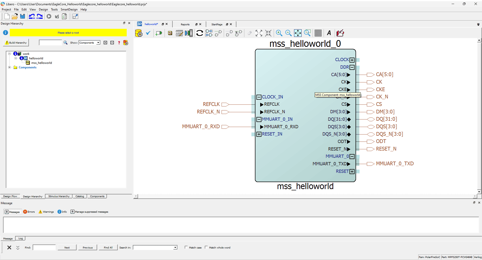
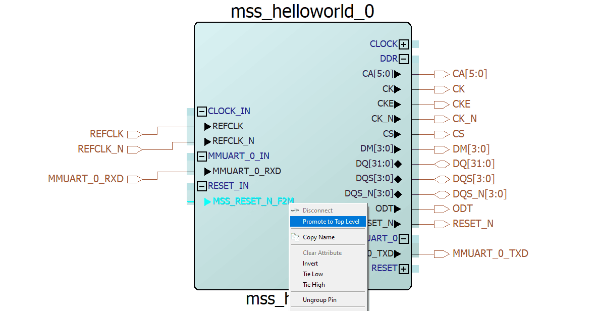
Step 13:
After instantiating the MSS component within the SmartDesign, promote MSS_RESET_N_F2M to the top level.
Step 14:
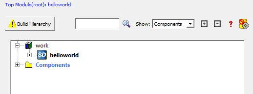
Now, click on “Generate Component” and ensure there are no detected errors. Set the SmartDesign as the root and click on “Build Hierarchy.”
Step 15:
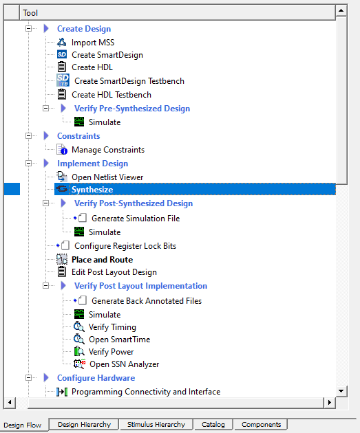
Proceed by clicking on “Synthesis” under “Implement Design” in the Design Flow tab.
Step 16;
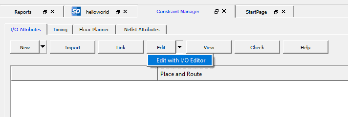
After the synthesis process is finished, double-click on “Manage Constraints” under the “Constraint” option. Then, select “Edit” under the I/O Attribute Tab within the constraint manager window, and choose “Edit with I/O Editor“.
Step 17:
Upon opening the I/O Editor window, you’ll see the complete set of constraints, which includes LPDDR4 and UART pins. You should focus on setting the constraint solely for the MSS reset and connecting the MSS Reset pin to H7. After making these adjustments, save and close the I/O Editor window.s
Step 18:
Now click Generate Bitstream, and wait for the bitstream to be generated.
SoftConsole
Import /driver-examples/mss/mss-mmuart/mpfs-mmuart-interrupt/ example project to a folder from PolarFire SoC GitHub.
Step 19:
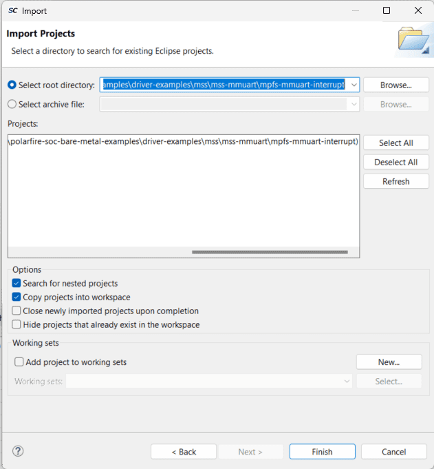
To import the UART bare metal project into the new SoftConsole project, go to the “Import projects” option. In the Select window, choose the import wizard as the “Existing projects into Workspace“. Click Next.
In the import project window, specify the root directory of the bare metal project. Click Finish.
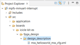
Step 20:
As the bare metal project was originally designed for the PolarFire SoC development kit, it’s necessary to replace the board XML file with the new XML file generated using the MSS configurator. To complete this, access the specified path and replace the file,
Step 21:
Before proceeding with project building, certain code modifications are required. As we’re utilizing solely the E51 core, we can amend the “mss_sw_config.h” file under “boards/icicle-kit-es/platform_config/mpfs_hal_config” to specifically use only core 0.
#ifndef MPFS_HAL_FIRST_HART
#define MPFS_HAL_FIRST_HART 0
#endif

#ifndef MPFS_HAL_LAST_HART
#define MPFS_HAL_LAST_HART 0
#endif
Step 22:
Now, it’s necessary to make modifications to the E51 application code. Please copy and paste the provided code below,
#include <stdio.h>
#include <string.h>
#include "mpfs_hal/mss_hal.h"
#include "drivers/mss/mss_mmuart/mss_uart.h"
volatile uint32_t count_sw_ints_h0 = 0U;

#define RX_BUFF_SIZE 16U
uint8_t g_rx_buff0[RX_BUFF_SIZE] = {0};
uint8_t rx_size0 = 0U;

const uint8_t e51_message[] = "Hello world";

void e51(void)
{
uint64_t hartid = read_csr(mhartid);

/* enable MMUART 0 */
(void) mss_config_clk_rst(MSS_PERIPH_MMUART0, (uint8_t) 1, PERIPHERAL_ON);

/* Init MMUART 0 */
MSS_UART_init(&g_mss_uart0_lo,
MSS_UART_115200_BAUD,
MSS_UART_DATA_8_BITS | MSS_UART_NO_PARITY | MSS_UART_ONE_STOP_BIT);

/* Send Message on uart0 */
MSS_UART_polled_tx(&g_mss_uart0_lo, e51_message,
sizeof(e51_message));

/* Clear pending software interrupt in case there was any. */
clear_soft_interrupt();
set_csr(mie, MIP_MSIP);

}

/* hart0 software interrupt handler */
void Software_h0_IRQHandler(void)
{
uint64_t hart_id = read_csr(mhartid);
count_sw_ints_h0++;
}
Step 23:
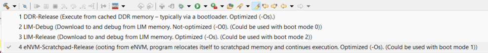
Now go to the Build options and select the build as “eNVM Scratchpad-Release“.
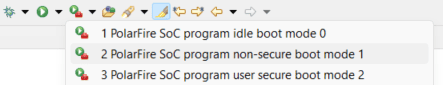
step 24:
After the project is built successfully, power up the device and establish a secure connection with the Flashpro programmer. Then, proceed to program the board by selecting the “PolarFire SoC program non-secure boot mode 1” option.
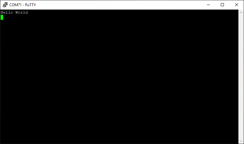
Step 25:
Once the programming is successful, launch the serial terminal and identify the correct COM port for MMUART0, which can be found in the device manager. You will then observe that the “Hello World” message is printed on the serial terminal, such as Putty.