Introduction:
Ethernet is a widely used protocol in the TCP/IP stack, enabling reliable communication between devices within a Local Area Network (LAN). The EagleCore ZU, powered by the Zynq UltraScale+ MPSoC with an integrated ARM Processing System (PS) and Programmable Logic (PL), provides a powerful platform for developing Ethernet-based applications. This design demonstrates an echo server using the lightweight IP (lwIP) TCP/IP stack, where the server receives TCP data and sends the same data back to the client.
The Zynq UltraScale+ Processing System uses the Gigabit Ethernet MAC (GEM) to interface with an external Ethernet PHY through the Reduced Gigabit Media Independent Interface (RGMII). This configuration highlights the tight hardware-software integration of the platform, enabling high-speed and efficient Ethernet communication for embedded networking applications.
Prerequisites
To follow this article, you would need the following:
- Hardware:
- EagleCore ZU-Plus MPSoC SOM.
- EagleCore ZUC02 Carrier.
- AMD Platform Cable II JTAG debugger.
- USB Type C Cable.
- 12V DC Power Supply.
- Cat 6 Ethernet Cable.
- Software:
- AMD Vivado Design Suite 2025.2
- Vitis 2025.2
- PUTTY Serial terminal.
Let’s get started
The following steps will walk you through the process of creating a new project with Vivado and building a hardware platform with Zynq Ultrascale+ processing system using IP integrator. This article is written for Numato Lab’s Eaglecore ZU-plus MPSoC SOM, but can be adapted to any other Zynq based platform with minor changes. Screenshots are added wherever possible to make the process easier to the reader.
Step 1:
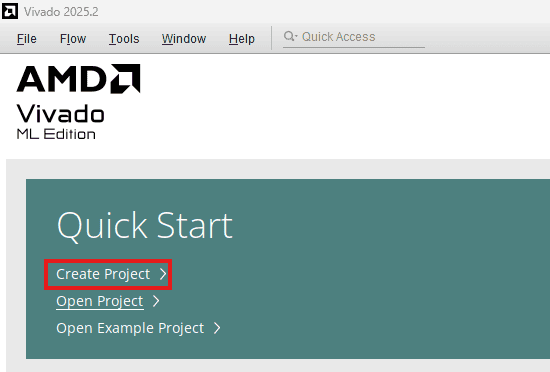
Start Vivado Design Suite, and select “Create New Project” from Quick Start section. The project wizard will pop up. Press next to proceed with creating the project.
Step 2:
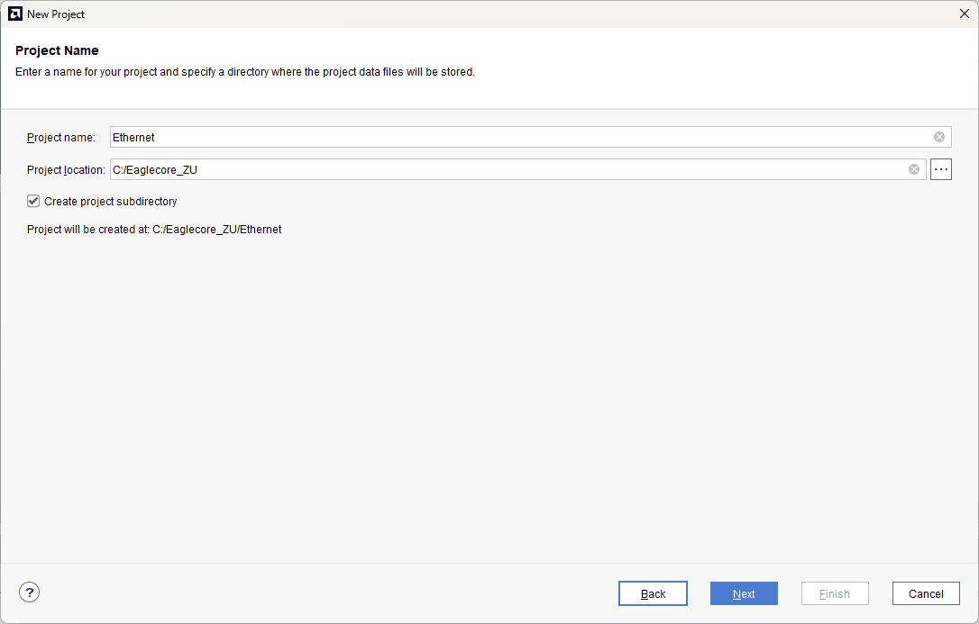
Type in a project name and save it at a convenient location. For this example “Ethernet” is used as project name, but feel free to use any name. Select the check box below to keep all project files in a single folder. The image below shows the settings for the example project. Click “Next” to continue.
Step 3:
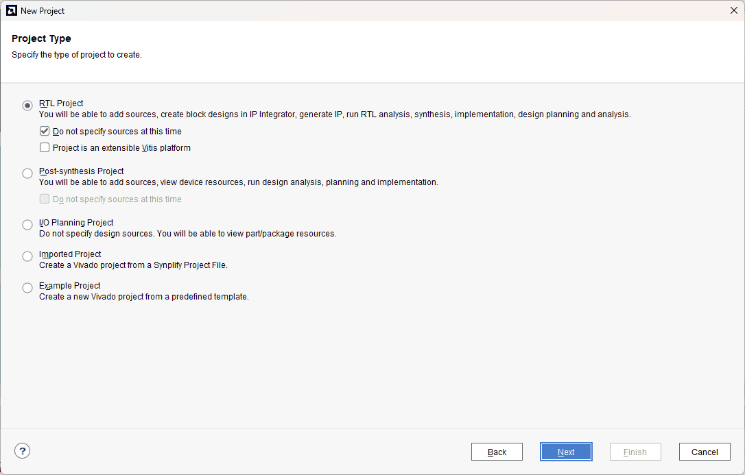
Choose “RTL Project” as project type and check the option “Do not specify sources at this time”.
Step 4:
At the “Default Part” stage, switch to the “Boards” tab and set the vendor to numato.com. Select “EagleCore Zu-plus development kit” and click Next. If the EagleCore Zu-plus development kit board does not appear in the list, click “Refresh” to update the board catalog. Vivado will then download the latest board files, after which EagleCore ZU-plus will become available for selection.
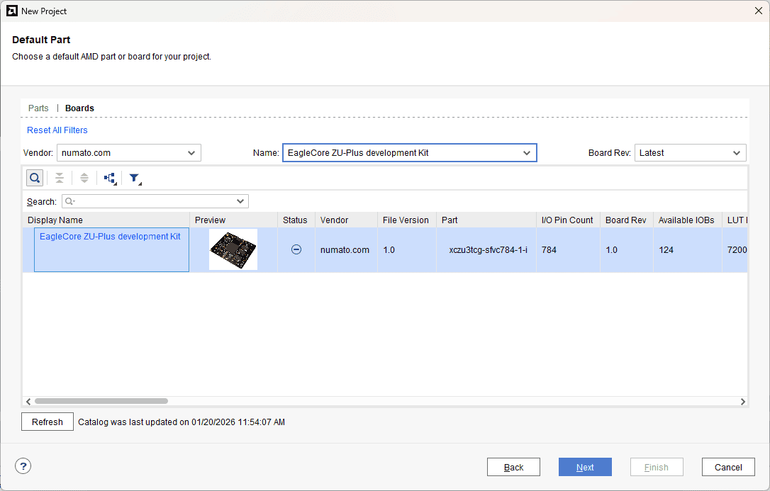
Continue the wizard and finish creating the project. When the new project wizard exits, a new project will be opened up in Vivado with the settings you have selected.
Step 5:
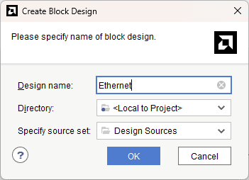
Under Flow Navigator, select “Create Block Design” in IP Integrator. Give an appropriate name to design. We will call it “Ethernet” for example.
Step 6:
Go to Diagram window, right click and select “Add IP” from the popup menu. Search for Zynq Ultrascale+ MPSoC. Add it to block design by double clicking.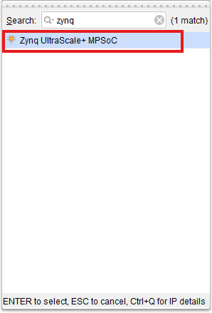
Step 7:
Click on “Run Block Automation” option on the green bar.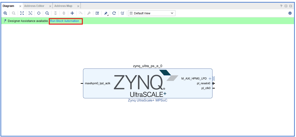
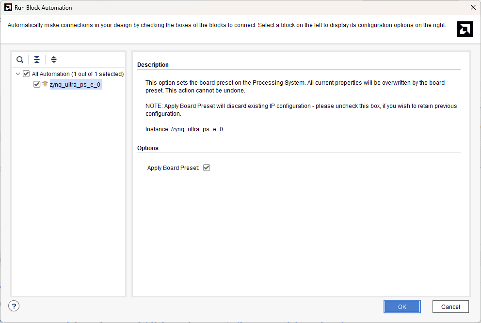
Step 8:
In the “Run Block Automation” window, select the options as in image below and click OK.
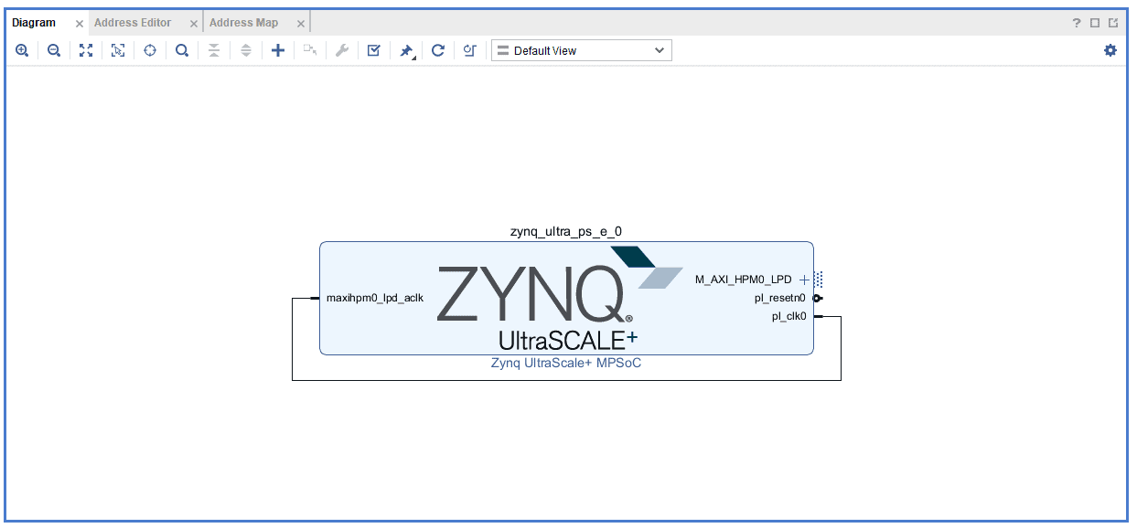
After running Block Automation, verify and complete the connections as shown in the image below.
Step 9:
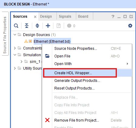
Go to “Sources” tab, right click on “Hello_world” design file and select “Create HDL Wrapper”. Click OK on the window that appears to finish generating wrapper
Step 10:
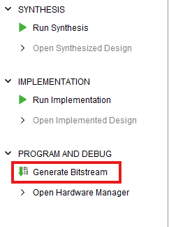
Click “Generate Bitstream” under PROGRAM AND DEBUG section and click “Yes” in any subsequent dialog window which comes up.
Step 11:
Once the bitstream is successfully generated, close any “Bitstream Generation Completed” dialog which comes up asking for what to do next , click OK.
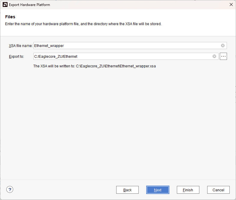
Go to File -> Export -> Export Hardware…
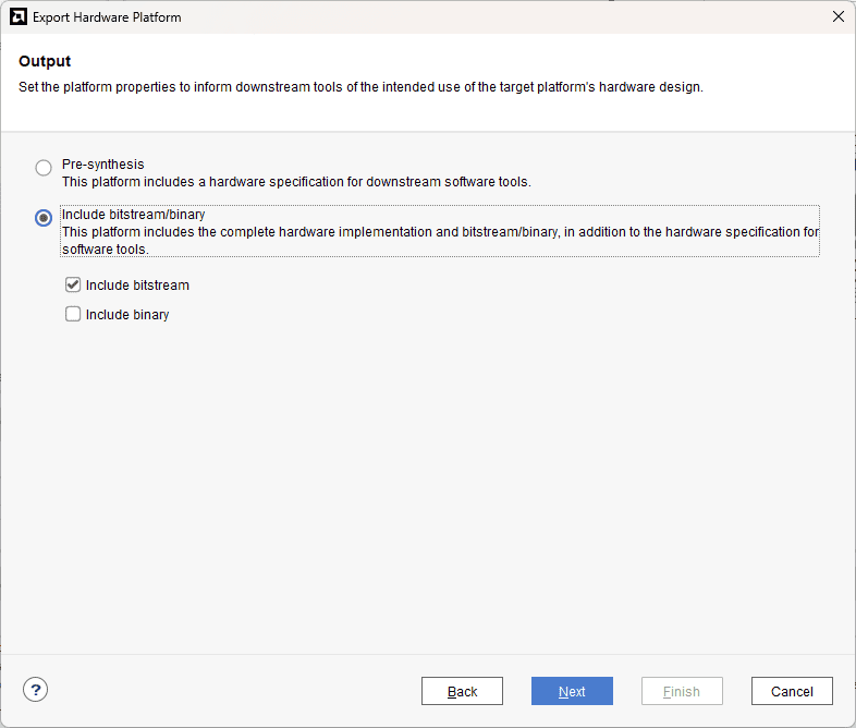
Check “Include bitstream”, keep “Export to:” default, and click OK.
Step 12:
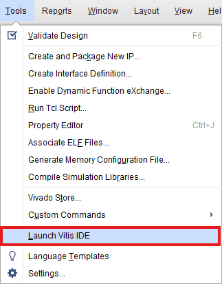
Select Launch Vitis IDE from the Tools menu.
Step 13:
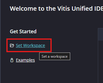
After Vitis Unified IDE window opens, click on “Set Workspace” and select necessary folder to keep the Vitis files.
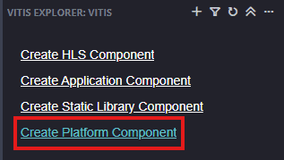
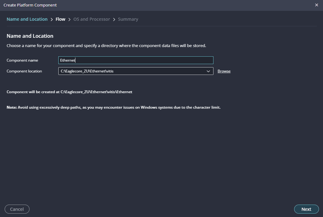
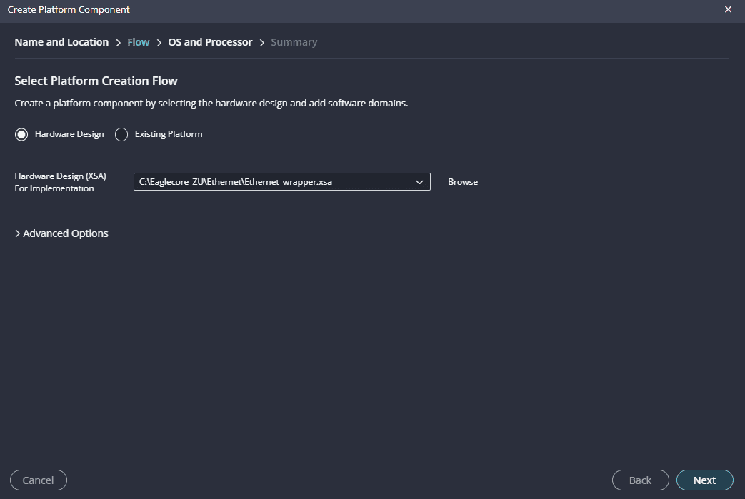
Step 14:
Create a new platform for the project, by selecting “Create Platform Component”, click “Next”, in the Flow tab select the XSA file saved using the step 11 and finally click “Next” and “Finish” respectively.
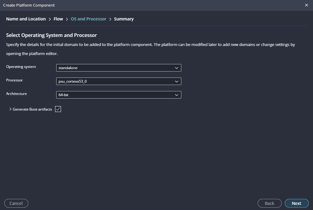
After successful creation of the platform, build the platform.
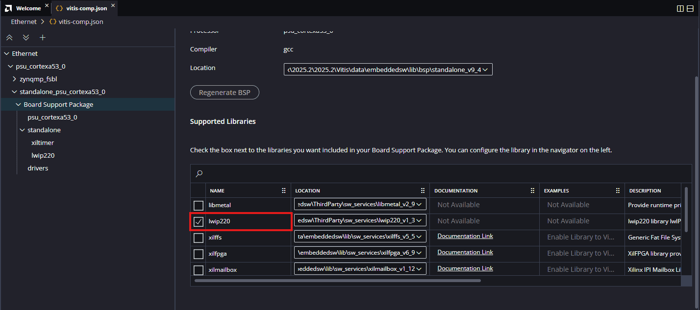
Step 15:
After building the platform go to Board Support Packages configuration of the newly created platform and add lwip220 library to the platform.
Step 16:
After adding lwip220 to the platform, click on the lwIP component to configure the lwIP library. Follow the procedure below to configure the lwIP library for the Echo Server application.
- lwip220_dhcp: True
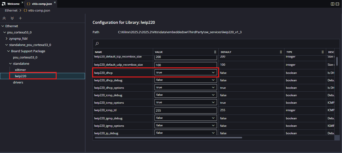
- lwip220_lwip_dhcp_does_acd_check: True
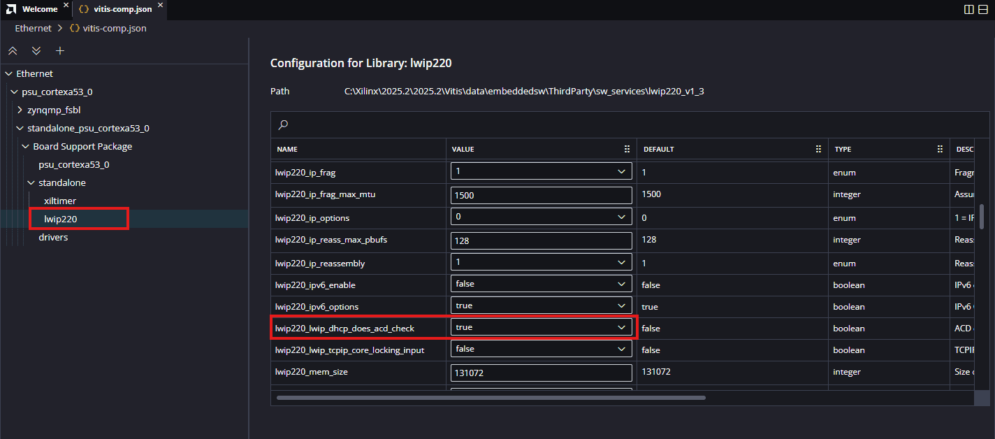
- lwip220_pbuf_pool_size: 2048
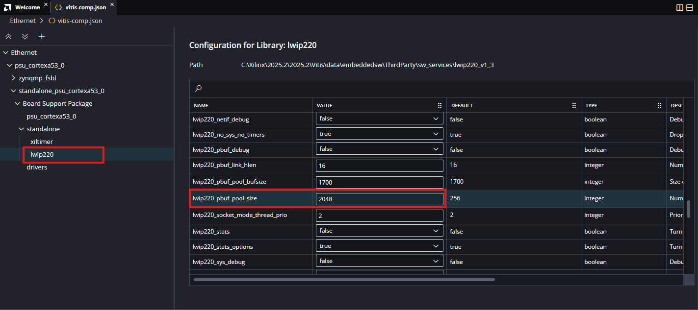
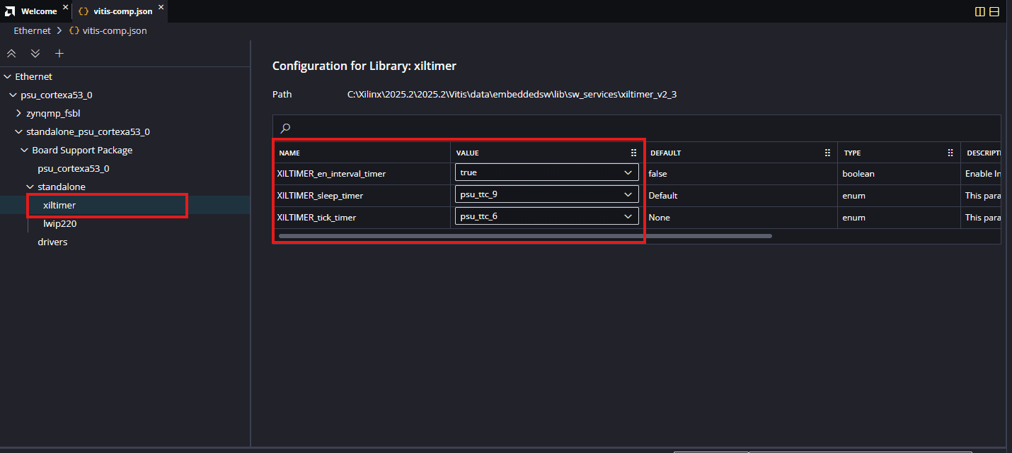
- xiltimer: XILTIMER_en_interval_timer: True (Make sure the configuration for xiltimer is same as below)
Once these parameters are set, you can add the lwIP echo server application to the platform.
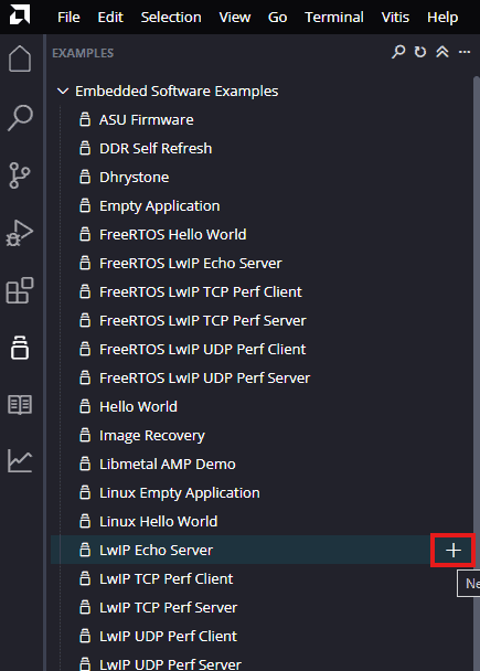
Step 17:
Next create the lwip echo server Application component by selecting the “IwIp Echo Server” template from the “examples”.
In “Create Application Component” tab specify project name and location, click “Next”.
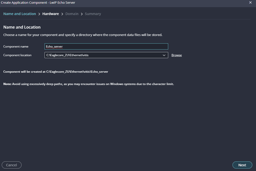
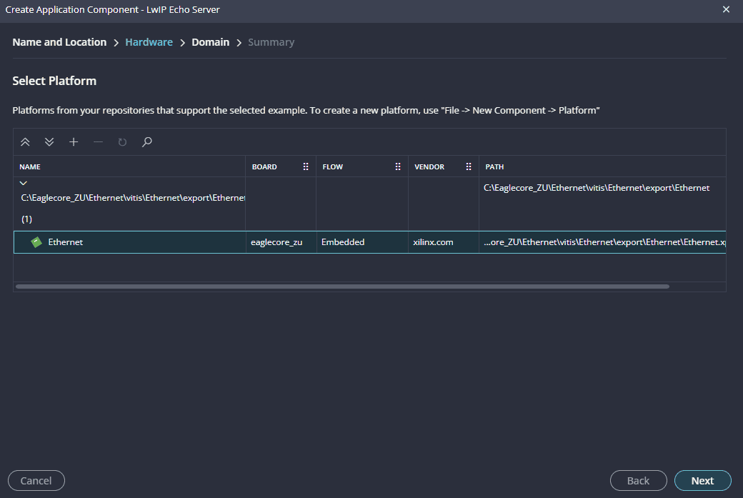
Select newly created Platform and click “Next”.
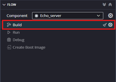
When the lwip project is added successfully, build the project manually.
NOTE: Vitis does not include built-in support for KSZ Ethernet PHY drivers. To enable compatibility, the xemacpsif_physpeed.c file must be manually updated with the required KSZ driver modifications.
Replace the existing file located at:Ethernet(platform)\psu_cortexa53_0\standalone_psu_cortexa53_0\bsp\libsrc\lwip220\src\lwip-2.2.0\contrib\ports\xilinx\netif\xemacpsif_physpeed.c
with the provided modified version. This ensures proper Ethernet functionality in your application.
After replacing the xemacpsif_physpeed.c file, build the project again.
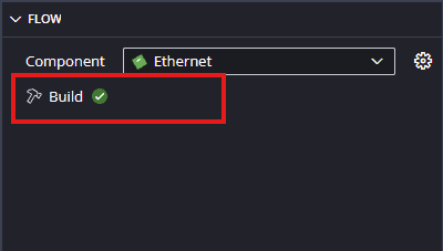
Step 18:
Once the build is completed successfully, power up the EagleCore ZU module using an external 12V DC power supply. Then, connect a Type-C cable to program the board (Note: ensure that PGM SEL is set to USB programming).
Step 17:
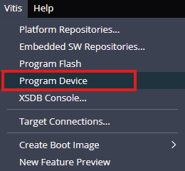
Program the FPGA on EagleCore ZU with a simple boot loop program by selecting the Program Device option from the Vitis menu.
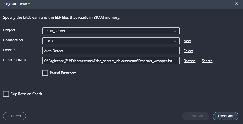
Once the “Program Device” window opens click on “Program“.
After programming the board, connect the Ethernet cable between the EagleCore board and the server.
NOTE: Ensure that your PC is connected to the same network gateway.
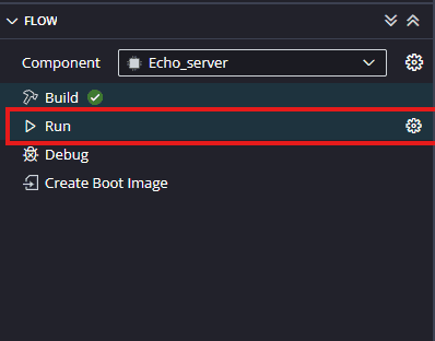
Step 19:
Meanwhile, open any serial terminal program (such as PuTTY, Teraterm etc) and open the port corresponding to Eaglecore ZU with a 115200baud rate. Program the board by selecting the “Run”.
Step 20:
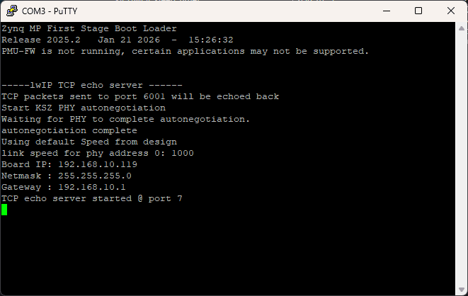
Observe the details displayed on the serial terminal.
Step 21:
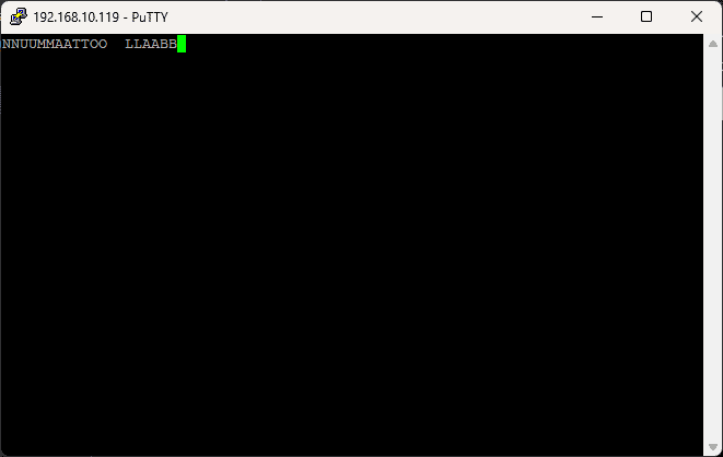
Open a telnet session with IP Address 192.168.10.119 (IP address as per serial terminal) at port 7, give input through the keyboard and observe the output. If you enter a character from the keyboard, you can observe the transmitted and echoed characters on telnet as shown.