Introduction:
PCI Express (PCIe) is a high-speed serial interface used to connect peripheral devices with fast data transfer and low latency. Unlike older PCI buses, PCIe uses point-to-point links, so each device gets a dedicated connection without sharing bandwidth. In the Zynq UltraScale+ MPSoC, PCIe support is built into the Processing System (PS), making it easier to test and connect with external devices. In this article, we will set up a simple design to test PCIe in the PS section and perform basic data transfers. Let’s get started!
Prerequisites
To follow this article, you would need the following:
- Hardware:
- EagleCore ZU-Plus MPSoC SOM.
- EagleCore ZUC02 Carrier.
- AMD Platform Cable II JTAG debugger.
- USB Type C Cable.
- 12V DC Power Supply.
- Software:
- AMD Vivado Design Suite 2025.1
- Vitis 2025.1
Let’s get started
The following steps will walk you through the process of creating a new project with Vivado and building a hardware platform with Zynq processing system using IP integrator. This article is written for Numato Lab’s EagleCore ZU-plus MPSoC, but can be adapted to any other Zynq UltraScale+ MPSoC based platform with minor changes. Screenshots are added wherever possible to make the process easier to the reader.
Step 1:
Download and install Vivado Board Support Package files for EagleCore ZU-Plus MPSoC SOM from here. Follow the readme in the link on how to install Vivado Board Support Package files for Numato Lab’s boards.
Step 2:
Start Vivado Design Suite, and select “Create Project” from Quick Start section. The project wizard will pop up. Press “next” to proceed with creating the project.
Step 3:
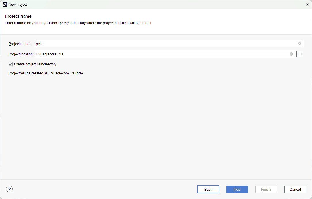
Type in a project name and save it at a convenient location. For this example “pcie” is used as project name, but feel free to use any name. Select the check box below to keep all project files in a single folder. The image below shows the settings for the example project. Click “Next” to continue.
Step 4:
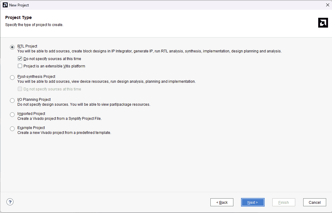
Choose “RTL Project” as project type and check the option “Do not specify sources at this time”.
Step 5:
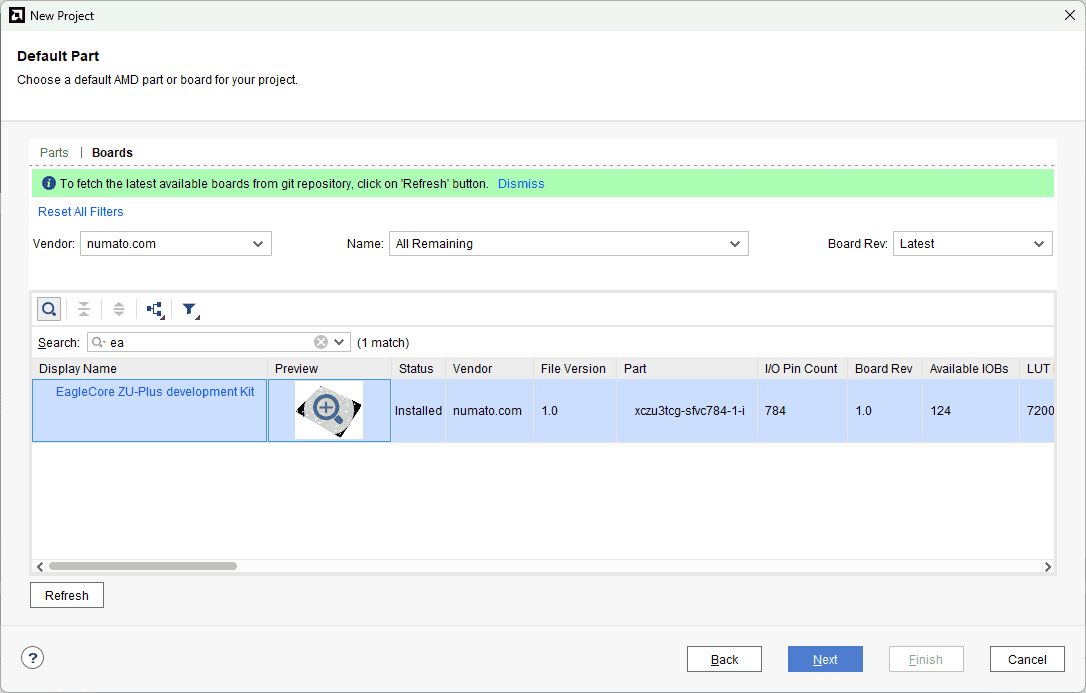
At the “Default Part” step, select “Boards” and choose Vendor as “numato.com”. Select “Eaglecore ZU-Plus development kit” and click “Next”. If Eaglecore ZU-Plus development kit is not displayed in the boards list, you will need to install Eaglecore ZU-Plus development kit board support files correctly.
Step 6:
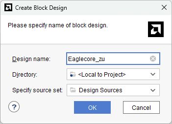
Under Flow Navigator, select “Create Block Design” in IP Integrator. Give an appropriate name to design. We will call it “Eaglecore_zu” for example.
Step 7:
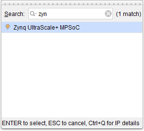
Go to Diagram window, right click and select “Add IP” from the popup menu. Search for Zynq UltraScale+ MPSoC. Add it to block design by double clicking.
Step 8:
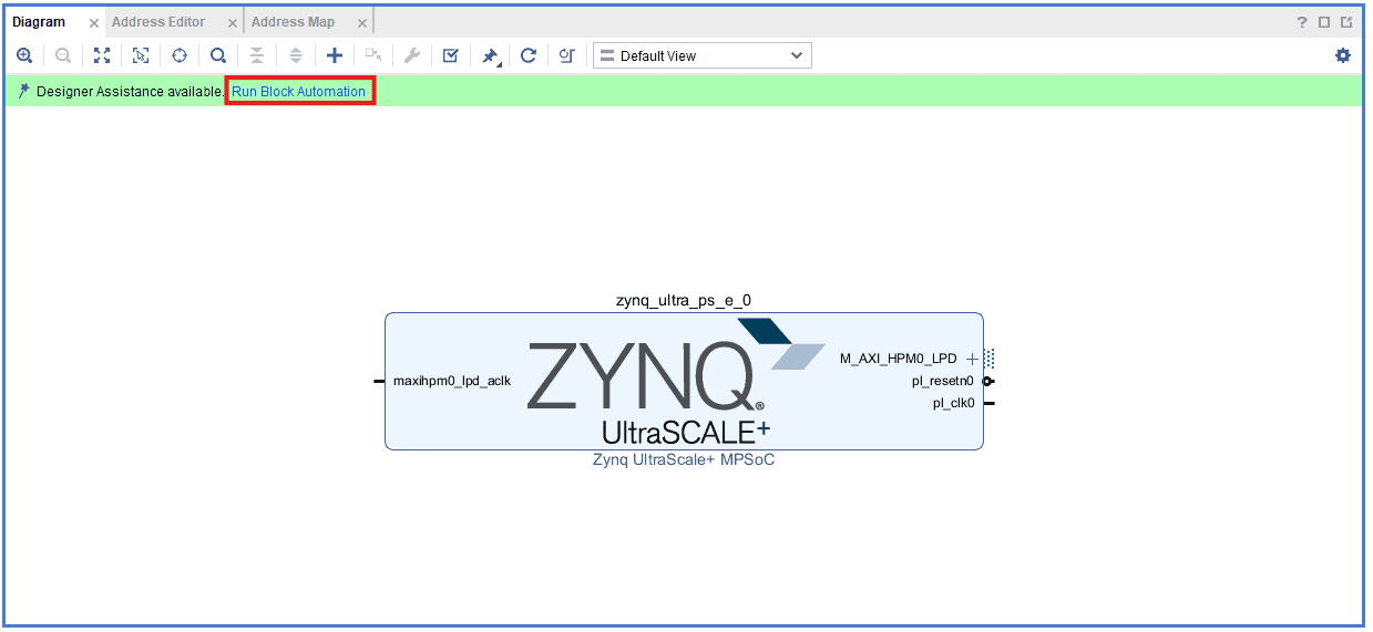
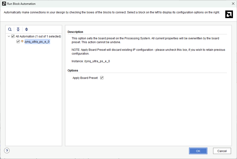
Click on “Run Block Automation” option on the green bar.
Step 9:
In the “Run Block Automation” window, select the options as in image below and click OK.
Step 10:
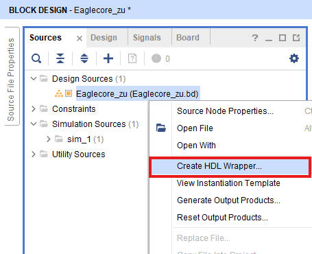
Go to “Sources” tab, right click on “Eaglecore_zu” design file and select “Create HDL Wrapper”. Click OK on the window that appears to finish generating wrapper.
Step 11:
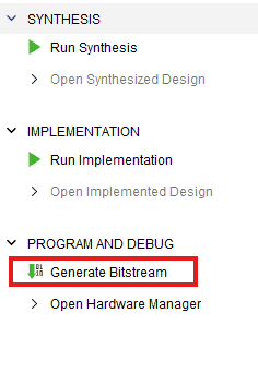
Click “Generate Bitstream” under PROGRAM AND DEBUG section and click “Yes” in any subsequent dialog window which comes up.
Step 12:
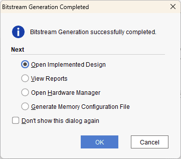
Once the bitstream is successfully generated, close any “Bitstream Generation Completed” dialog which comes up asking for what to do next.
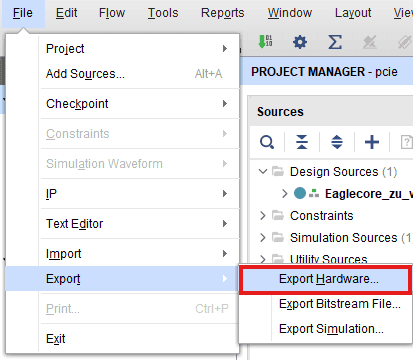
Go to File -> Export -> Export Hardware…
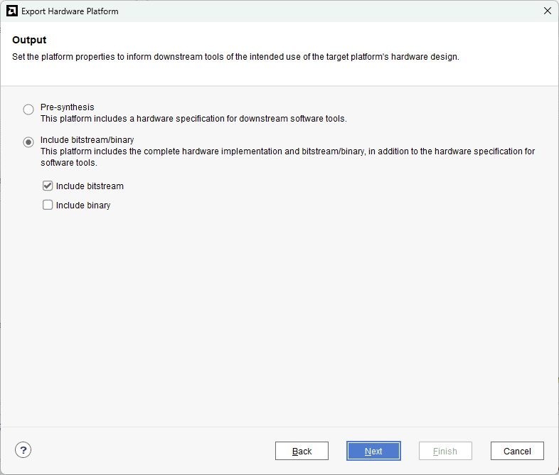
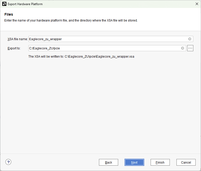
Check “Include bitstream”, keep “Export to:” default, and click OK.
Step 13:
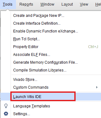
Select Launch Vitis IDE from the Tools menu.
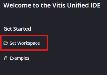
Step 14:
After Vitis Unified IDE window opens, click on “Set Workspace” and select necessary folder to keep the Vitis files.
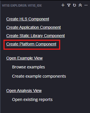
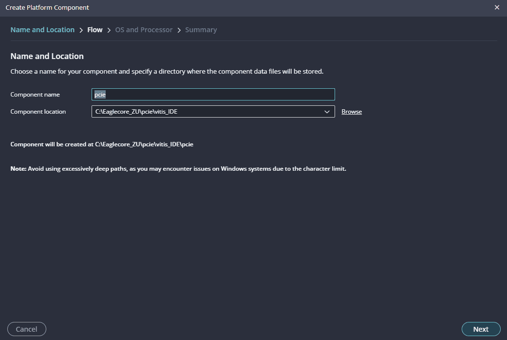
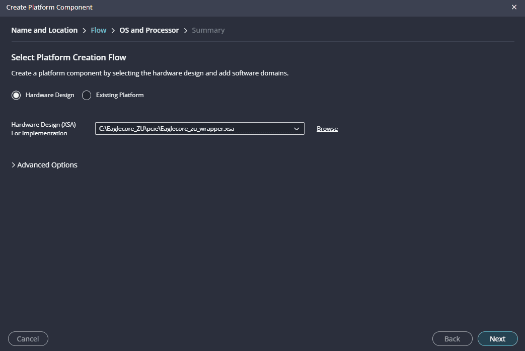
Step 15:
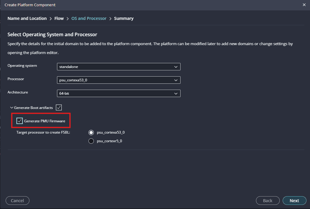
Create a new platform for the project, by selecting “Create Platform Component”, click “Next”, in the Flow tab select the XSA file saved using the step 12 and finally click “Next” and “Finish” respectively.
Enable Generate PMU Firmware under Generate Boot artifacts section.
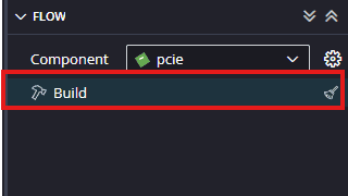
After successful creation of the platform, build the platform.
Step 15:
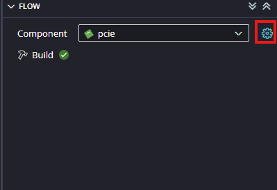
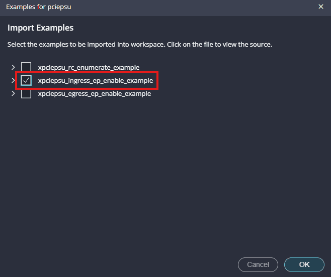
Once the platform is built successfully, the next step is to add an application by using the Import Examples option in the BSP of the platform.
To open the BSP, click on the settings icon as shown in the image below.
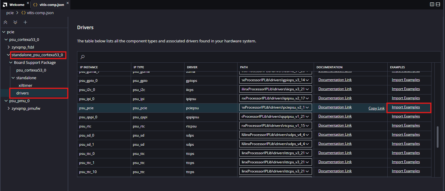
Add the xpciepsu_ingress_ep_enable_example application from the psu_pcie driver section, as shown in the image below.
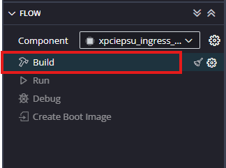
After adding the application, build the application.
Step 16:
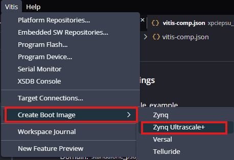
Create a boot image and program the QSPI flash by following the steps below.
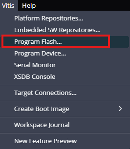
From the Vitis toolbar, click on Create Boot Image → Zynq UltraScale+, as shown in the image below.
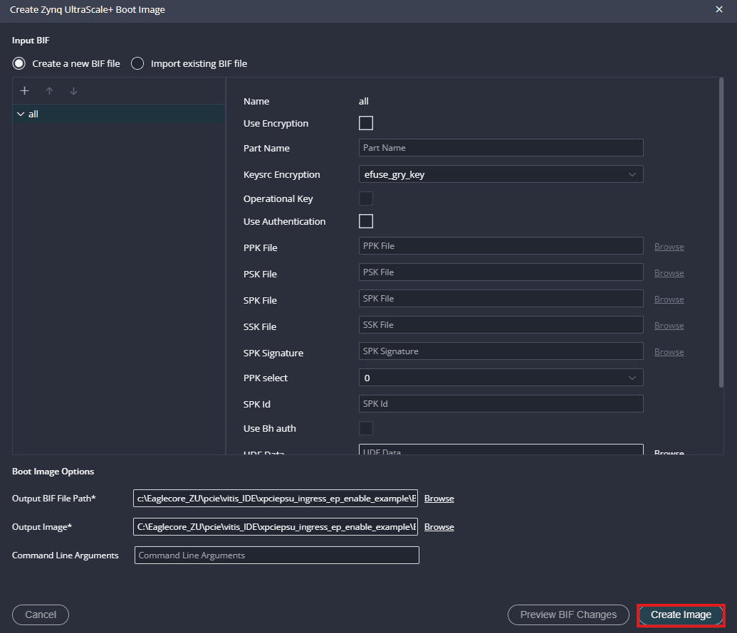
Select an output BIF file path to save the BOOT.bin file.
Click on Create Image to generate the boot file.
Step 17:
After successfully creating the boot image, power up the EagleCore ZU module using an external 12V DC power supply. Then, connect a Type-C cable to program the board (Note: ensure that PGM SEL is set to USB programming).
Step 18:
From the Vitis toolbar, click on Program Flash. Select the appropriate .bin file to be programmed, then configure the remaining options as shown in the image below to successfully program the flash.
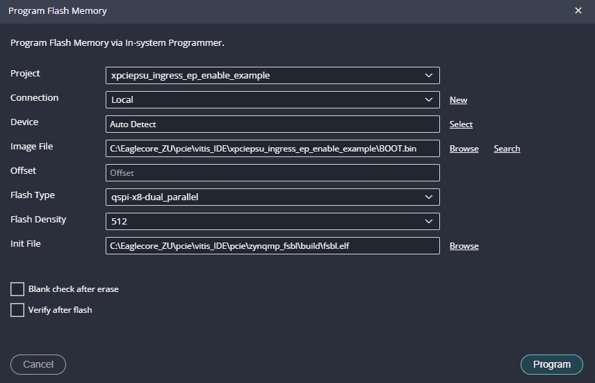
NOTE: while programming the QSPI, please ensure that the BOOT Mode is in JTAG Boot.
Step 19:
Once the device is programmed, Change the BOOT mode to QSPI BOOT, test it on a Linux machine.
Communicating with Eaglecore ZU via PCI Express on Linux Machines:
Step 1:
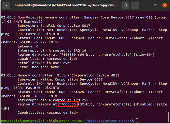
Download the complete pcimem application code zip file and unzip it in a specific location. Go to the command line terminal and check the PCIe base address by using the command
lspci -vv the output of the command is shown below. Make sure the Eaglecore ZU Board is inserted correctly into the PCIe Slot of host system’s motherboard. If the host is unable to detect Eaglecore ZU(which should show up as “RAM memory: Xilinx Corporation” as in the image below), make sure the board is inserted correctly into PCIe Slot and do a soft-reset after the host is powered up. A soft-reset after the host is powered up helps the host detect FPGA based PCIe devices.
Step 2:
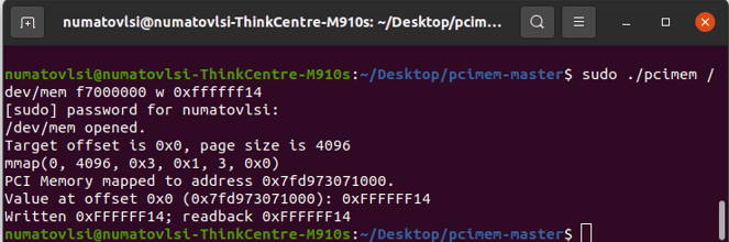
In command line terminal, open the path where you saved the ‘pciemem’ code. First compile the C program by using the command “make”. Once it is compiled successfully, use the following command:
sudo ./pcimem /dev/mem f7000000 w 0xffffff14
Here,
f7000000: indicates the base address + offset, it is the address to which write is performed.
w: indicates whether it is word, byte or half word.
0xffffff14: 32-bit data value for write purpose.
You will observe the following output indicating that the 32-bit data has been written to the specified address and read back from it. If the written data matches the data read, it means data was successfully written to Eaglecore ZU.