Getting Started with Elbert S7
Now, let’s turn our attention to the Elbert S7 FPGA board—a beginner-friendly platform designed to ignite your passion for FPGA development.
Here’s what you need to begin your journey:
Hardware: The Elbert S7 FPGA board, equipped with a AMD Spartan-7 FPGA
Software: Vivado Design Suite 2024.1, a comprehensive toolchain for designing, synthesizing, and implementing FPGA projects.
Starting Your First Project
With the groundwork laid, it’s time to start your FPGA project with the Elbert S7 board. Here’s a glimpse of what awaits:
- Setting up the Environment: Configure your development environment and establish communication with the Elbert S7 board.
- Writing Verilog Code: Craft your digital masterpiece using Verilog, a hardware description language akin to writing software in C.
- Synthesizing and Implementing: Transform your Verilog code into a tangible design by synthesizing and implementing it on the FPGA.
- Testing and Debugging: Validate the functionality of your project and fine-tune it using debugging techniques to ensure optimal performance.
Procedures to Create a NAND gate project using Vivado
Step 1:
Download and install Vivado Board Support Package files for Elbert S7 from here. Follow the readme in the link on how to install Vivado Board Support Package files for Numato Lab’s boards.
Step 2:
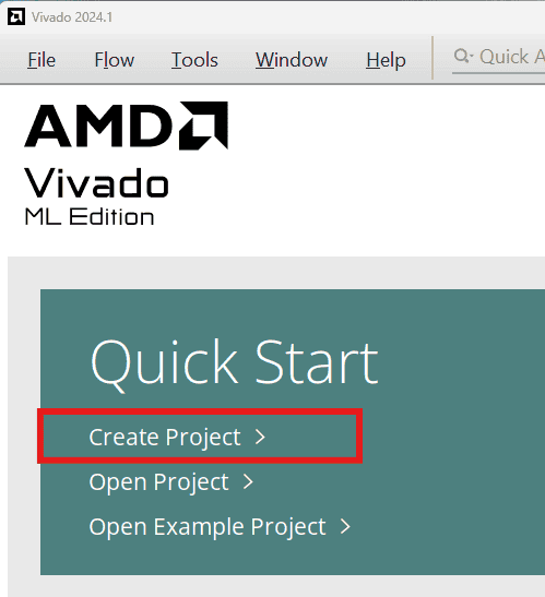
Start Vivado Design Suite, and select “Create Project” from Quick Start section. The project wizard will pop up. Press next to proceed with creating the project.
Step 3:
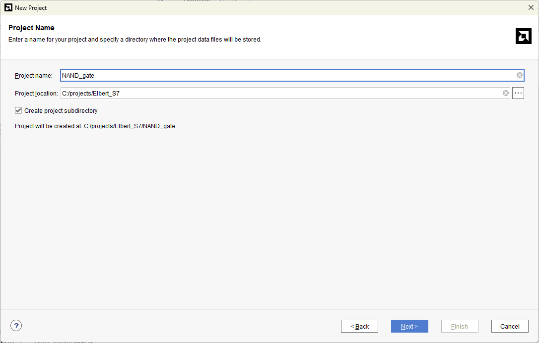
Type in a project name and save it at a convenient location. For this example “vga” is used as project name, but feel free to use any name. Select the check box below to keep all project files in a single folder. The image below shows the settings for the example project. Click “Next” to continue.
Step 4:
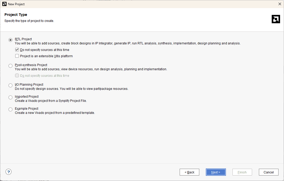
Choose “RTL Project” as project type and check the option “Do not specify sources at this time”.
Step 5:
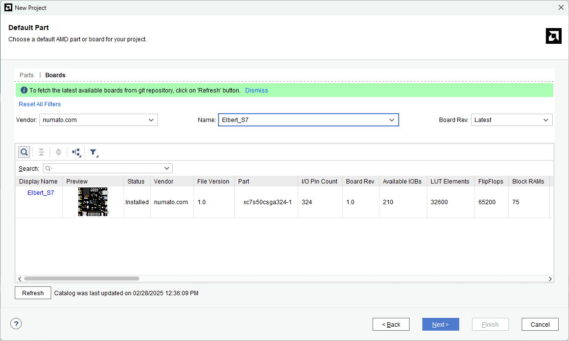
At the “Default Part” step, select “Boards” and choose Vendor as “numato.com”. Select “Elbert_S7” and click “Next”. If Elbert is not displayed in the boards list, you will need to install Elbert board support files correctly.
Step 6:
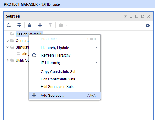
Then in the Sources tab, Right-click Design Sources and click ‘Add Sources’. It will open a new “Add Sources” window.
Step 7:
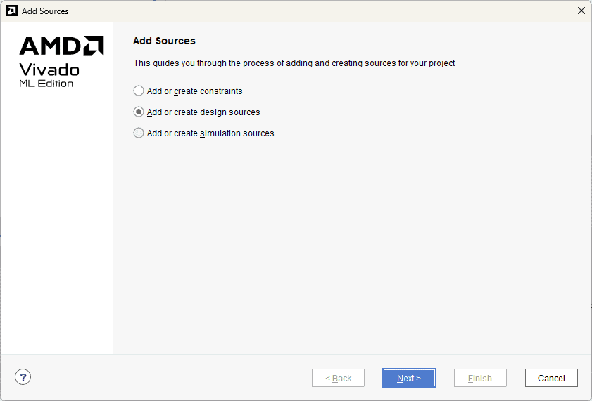
In Add sources tab select “Add or create design sources” and Click on “Next“.
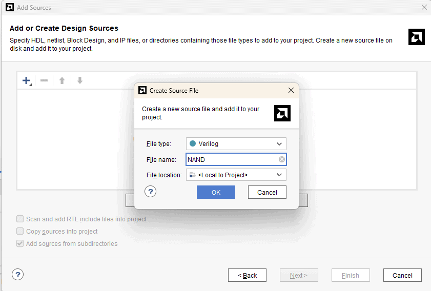
In ‘Add or Create Design Sources’, select ‘Create File’, give ‘NAND’ as file name. Click OK and Finish.
Step 8:
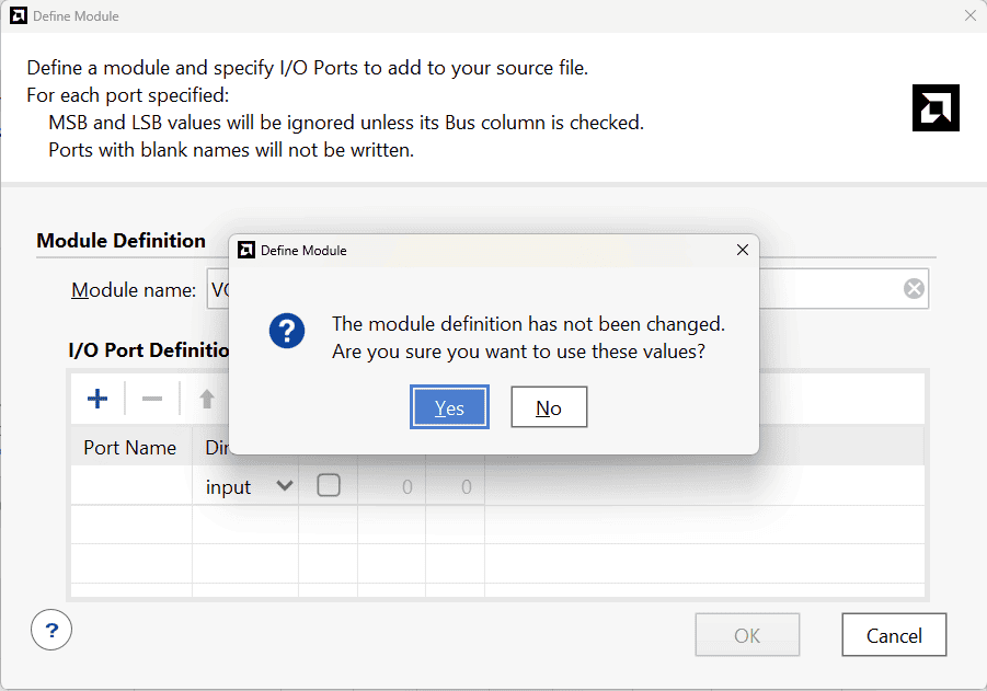
In the ‘Define Module’ window, Click ‘OK’ followed by ‘Yes’ without making any changes.
Step 9:
Copy the following code in NAND.v and save the file.
module nand_gate (
input a,    // First input
input b,    // Second input
output reg y // Output defined as 'reg' for behavioral modeling
);

// Behavioral description using always block
always @(*) begin
    if (a & b)
        y = 0;  // NAND logic: If both inputs are 1, output is 0
    else
        y = 1;  // Otherwise, output is 1
end
endmodule
Step 10:
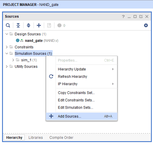
Right click on the simulation sources and click on Add sources
Step 11:
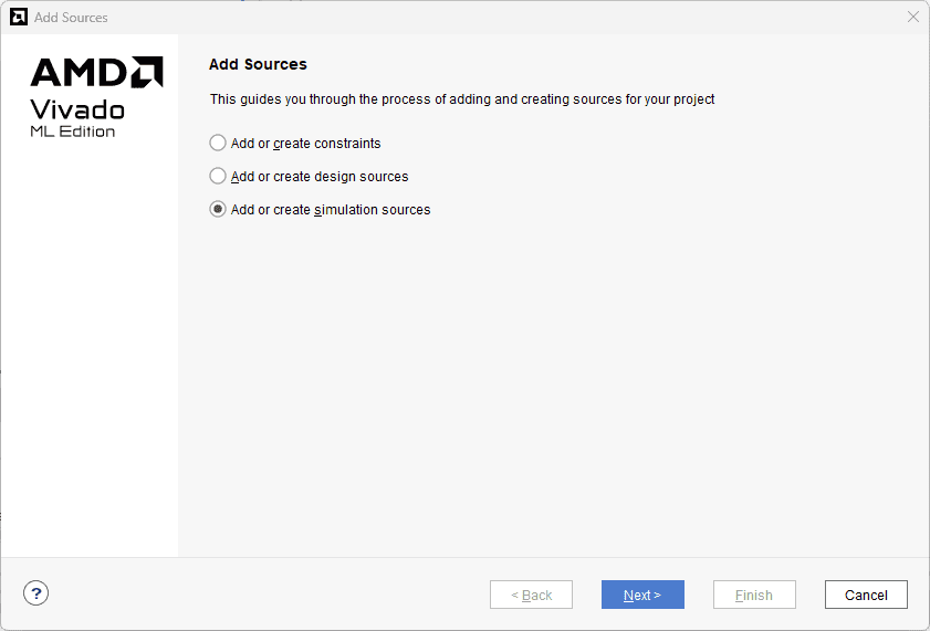
Select “Add or create simulation” sources and click next
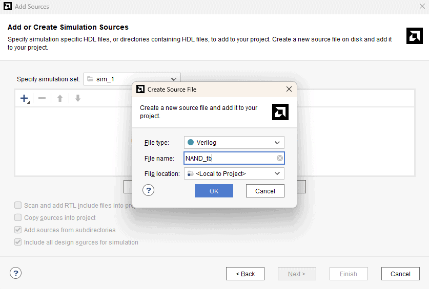
In ‘Add or create simulation’, select ‘Create File’, give ‘NAND_tb’ as file name. Click OK and Finish.
In the ‘Define Module’ window, Click ‘OK’ followed by ‘Yes’ without making any changes.
Step 12:
Copy the following code in NAND_tb.v and save the file.
module nand_gate_tb;
// Testbench signals
reg a, b;
reg clk;        // Clock signal
wire y;

// Instantiate the NAND gate module
nand_gate uut (
    .a(a),
    .b(b),
    .y(y)
);

// Clock generation - 10ns period (5ns HIGH, 5ns LOW)
initial clk = 0;
always #5 clk = ~clk;

// Stimulus process
initial begin

    // Input combinations changing every 10ns
    a = 0; b = 0; #10; // Expect y = 1
    a = 0; b = 1; #10; // Expect y = 1
    a = 1; b = 0; #10; // Expect y = 1
    a = 1; b = 1; #10; // Expect y = 0
    $finish; // End simulation
end
endmodule
Step 13:
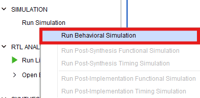
under “Flow navigator” click on “Run simulation” and select Run “Behavioural Simulation”
Step 14 :
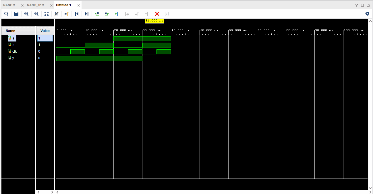
Now the built-in simulator will start and you will be presented with a simulation waveform like the one below (Sometimes you may have to zoom in/out a little bit to see the waveform correctly).
Inspect the waveform and make sure that our Verilog module is working as expected. As you can see in the image below, the output is the low(0) only when both the inputs are high(1). This is exactly what we expect from an NAND gate.
In Next part of this tutorial, we will implement this module on a real hardware.