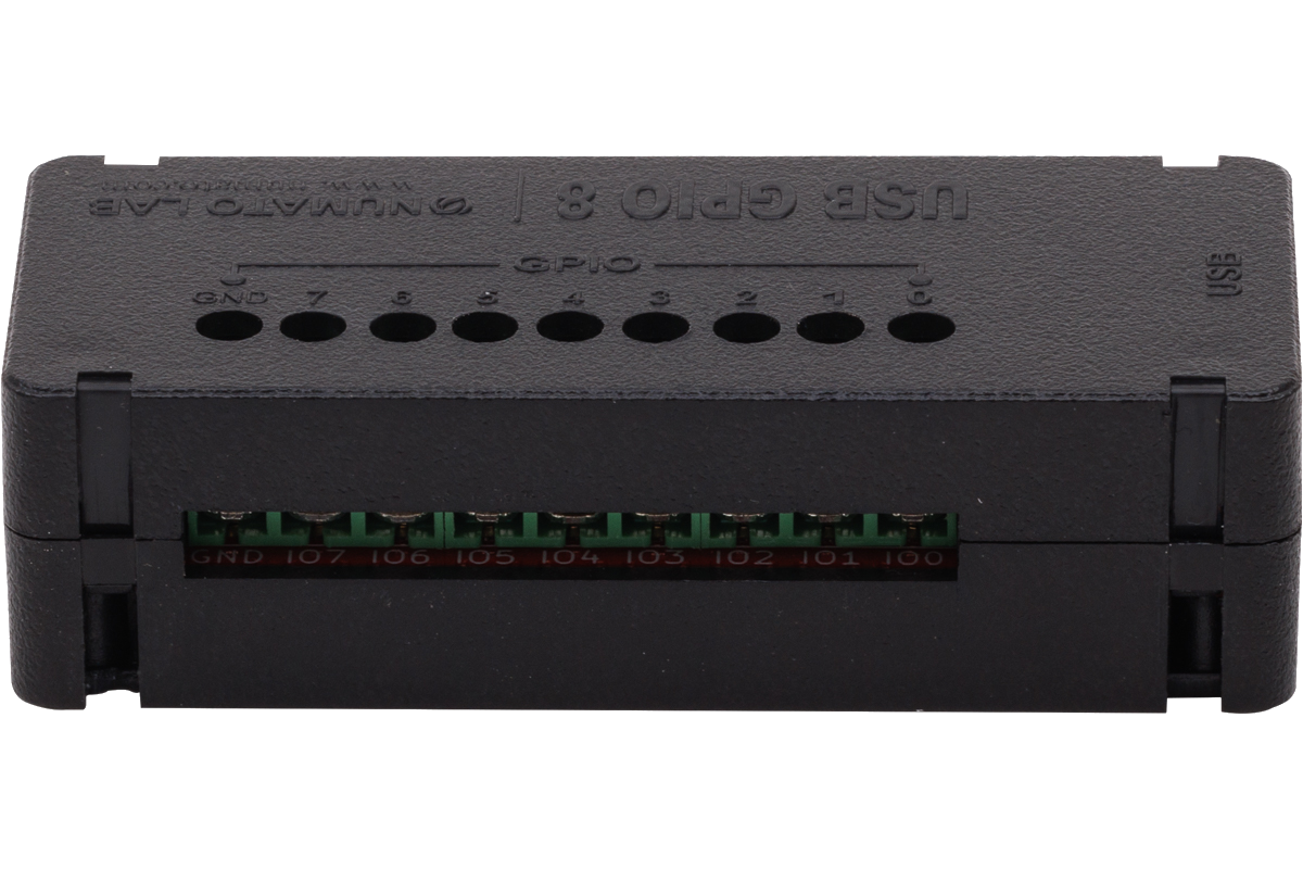
8 Channel USB GPIO Module With Analog Inputs
SKU: GP80001


Request For QuoteWanna Customize? Drop Us A Line!
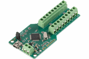
Numato Lab’s 8 Channel USB GPIO Module helps to connect real-world devices to your computer easily through USB. No USB specific knowledge is required to set up and use this module. Numato Lab’s GPIO devices provide an interface that looks like a Serial Port on your Operating System and thus effectively hiding the complexity of USB. All that you need to operate GPIOs is a standard Serial Terminal Emulator such as HyperTerminal/Teraterm or your favorite programming language such as C/C++, Python, Perl, etc… Besides providing standard General Purpose IOs, this product has multiple Analog Inputs as well. These Analog inputs can be used to read Analog quantities such as temperature, pressure, etc.. with the help of appropriate sensors.
Features
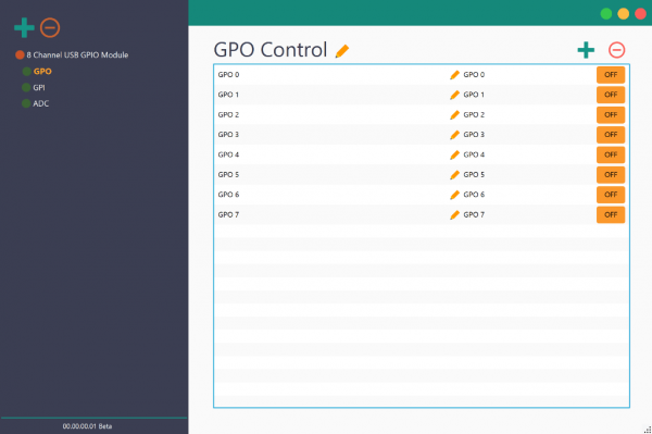
- Supported by Rhea Device Management Software
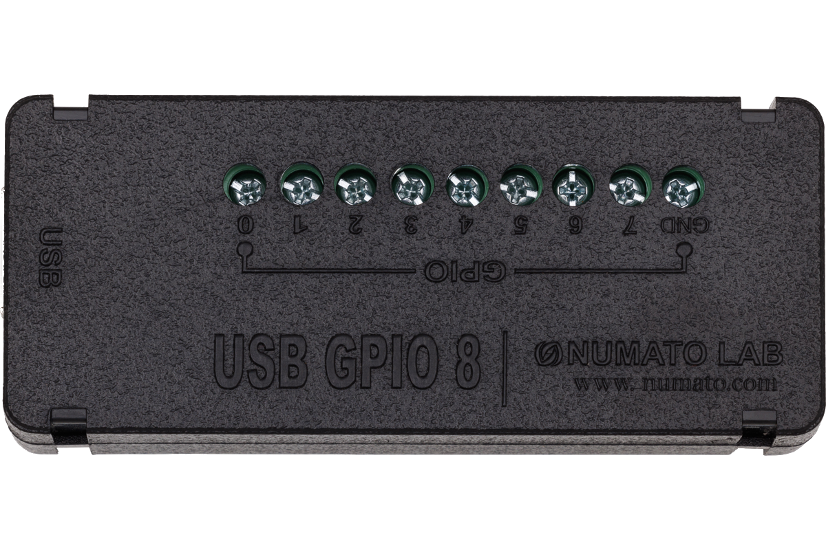
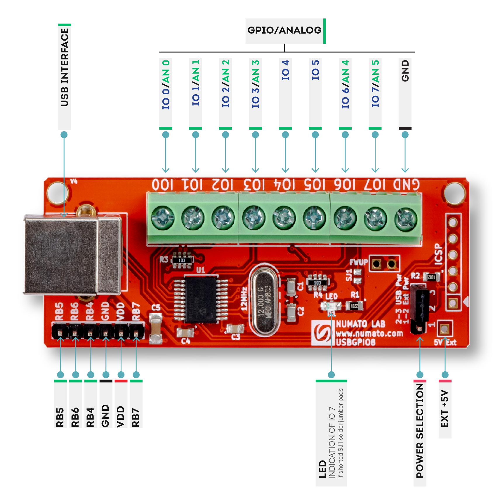
- 8 TTL (5V) compatible GPIOs available
- readall & writeall command support read/update all GPIOs with a single command
- 6 Analog input channels (Multiplexed with GPIOs)
- 10 Bit Analog input resolution
- All GPIOs can be individually configured as input or output.
- Can be controlled by using standard serial console applications or custom applications.
- Onboard controller can be reprogrammed for custom applications
Applications
- Building automated test fixtures
- Add more IOs and Analog channels to industrial/modular computers
- Add more IOs and Analog channels to Raspberry Pi, Intel Edison, BeagleBone and similar CPU boards
- Add IOs to Android-based systems (Smartphones, Tabs and custom devices)
Supported operating systems
- Windows XP
- Windows 7
- Windows 8/8.1
- Windows 10
- Linux
- Mac OS X
- Android
Why Numato Lab’s 8 Channel USB GPIO Module With Analog Inputs?
Building a computer or Smartphone controlled devices wasn’t always the easiest thing to do. Specialized knowledge in hardware and software was often needed to get even the simplest of things done. But what could you do if you can control devices from your Windows/Linux/Mac/Android device in less than five minutes? The possibilities are unlimited. Build a computer-controlled security system, an automated test fixture, a computer-controlled garage door, and much more with Numato Lab’s USB GPIO devices!
Numato Lab’s USB GPIO devices are designed to help customers to get started very easily and keep everything as simple as possible even when building complex systems. This goal is achieved by a few carefully designed features below.
- Simple USB-Serial interface
- Simple and easy to use commands
- No product-specific libraries or APIs
- Large verity of supported programming languages
- Huge collection of sample code to help you get started
 Simple USB-Serial interface
Numato Lab’s USB GPIO devices present themselves to the Operating System as a serial port. This means all the complexity related to USB is abstracted out and you will be using the device as if it is a simple serial port. This serial port interface can be accessed using a standard Serial Terminal Emulator software such as HyperTerminal, Teraterm, PUTTY, or through your own custom script or application that can be written using one of more than a dozen different programming languages. On Windows, the device will be visible in the Device manager as a normal serial port. On Linux and Mac, the device will be listed under /dev directory, usually with a name in the format ttyACMx. On Android, the device can be enumerated and controlled using packages provided by Android such as UsbManager, Usbdevice, UsbConfiguration, UsbDevice, UsbInterface, etc…
 Easy to use commands
Numato Lab’s USB GPIO devices support simple and human-readable commands to control the device (For example, command “gpio on 1” will turn ON GPIO1). These commands can be manually typed in through a standard Serial Terminal Emulator such as HyperTerminal or Teraterm and can also be sent from a custom application or script. Custom applications or scripts can be used to automate the interaction with the device and implement logic such as conditional device control based on input values or timer etc…
No product-specific libraries or APIs
Unlike many other USB GPIO devices, Numato Lab’s GPIO devices do not depend on any third-party library of API. The device can be accessed by using the serial port access APIs natively provided by the Operating System where available. That being said, libraries do exist on many platforms that may make accessing devices easier. But their use is fully optional.
Large number of supported programming languages
If the particular language of your choice supports serial ports, it should be possible to use that language to write custom script or application on an Operating System that supports USB Serial Ports. Currently, Numato Lab’s GPIO devices are tested on different Windows versions, Linux, Mac, and Android. A script or application can be written using but not limited to C, C , Visual Basic, Java, C#, AutoHotkey, VBA (MS Excel, MS Word, etc…), Node.js, Autoit, Labview, Perl, Java (Android), etc..


Large collection of sample code
Numato Lab provides dozens of sample code/projects that can be used to kick start your development (Please see Sample Code tab).
Specifications
| Attribute | Value |
|---|---|
| Weight | 0.1 lbs |
| Dimensions | 5 × 3 × 1 in |
| Product Dimensions | 2.81 x 1.07 x 0.55 in |
| Number Of GPIOs (Max) | |
| Analog Inputs(Max) | |
| Host Interface | |
| Analog Input Resolution | |
| Multiplexed Analog Inputs | |
| Pull-Up | With Pull-Up, Without Pull-Up |
| Operating Temperature | -30°C to +85°C |
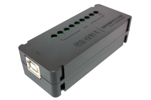
| Packaging | Without Enclosure, With Enclosure |
| Package Contents | |
| Warranty | |
| RoHS | Yes |
| SKU | GP80001 |
Sample Code
Sample Code
| Language/Technology | IDE/Compiler | Type | OS | Download link |
|---|---|---|---|---|
| C | VCExpress2008 | Command Line | Windows | Download |
| C | VCExpress2010 | Command Line | Windows | Download |
| Visual Basic | VBExpress2008 | GUI | Windows | Download |
| Visual Basic | VBExpress2010 | GUI | Windows | Download |
| Visual Basic | Visual Basic 6 | GUI | Windows | Download |
| C | Visual C++ 6 | Command Line | Windows | Download |
| Python | Python | Command Line | Windows | Download |
| Java | NetBeans | Command Line | Any | Download |
| C# | Visual Studio 2012 | GUI | Windows | Download |
| AutoHotkey | AutoHotkey | GUI | Windows | Download |
| VBA | MS Excel 2010 | GUI | Windows | Download |
| VBA | MS Word 2010 | GUI | Windows | Download |
| Visual Basic | JustBASIC | NA | Windows | Download |
| Javascript | Node.js | Command Line | Windows | Download |
| AutoIt | AutoIt | NA | Windows | Download |
| Labview | Labview | Simple GUI | Any | Download |
| Perl | Perl | Command Line | Linux | Download |
| Perl | Perl | Command Line | Windows | Download |
| Android | Android studio | GUI | Windows | Download |