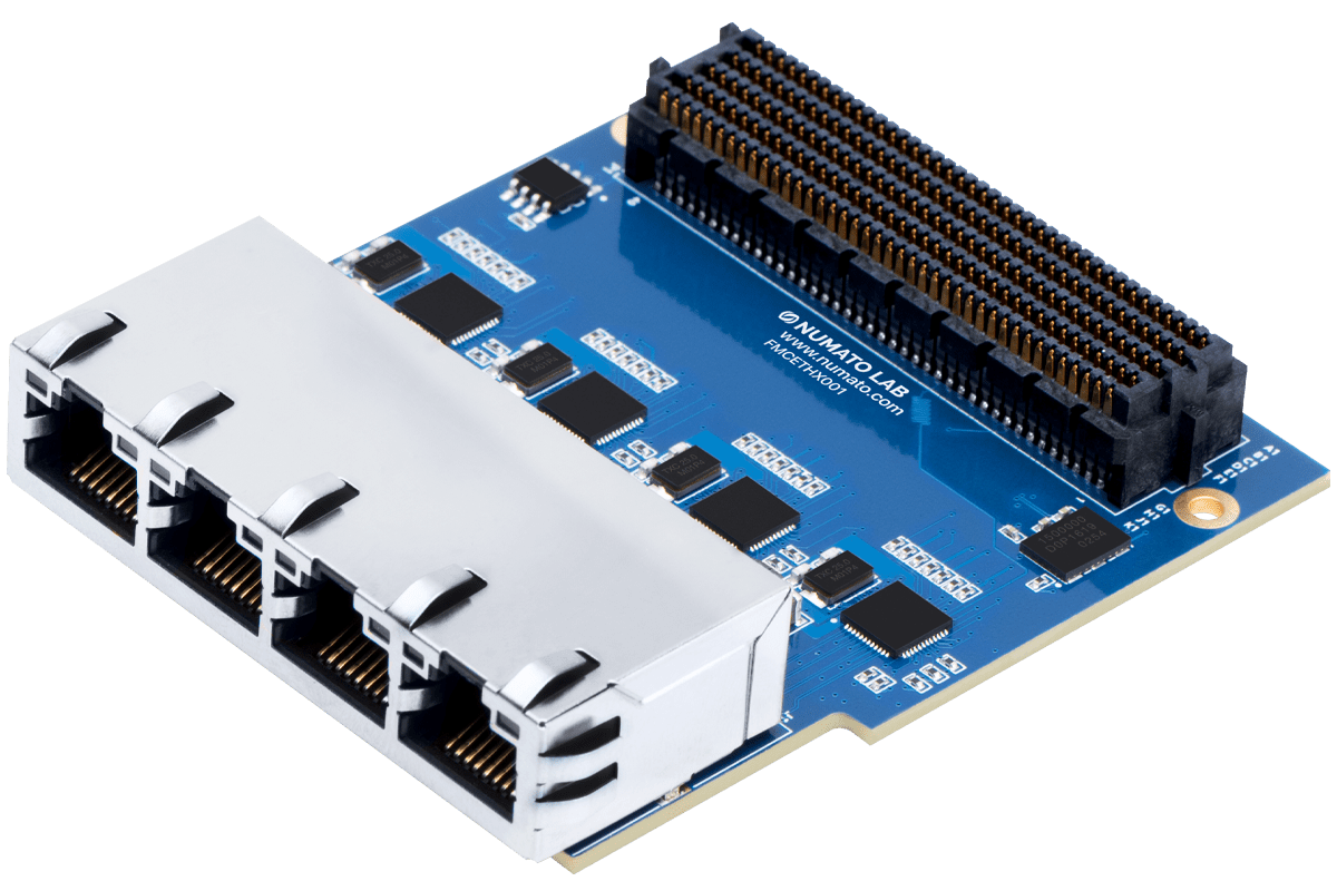
Quad Port Gigabit Ethernet FMC
The FMCETHX001 Ethernet Expansion Module includes 4 Gigabit Ports, each offering reliable transmission and reception capabilities at 10 Mbps, 100 Mbps, or 1000 Mbps. All 4 ports are also capable of operating simultaneously. FMCETHX001 module features RTL8211E Gigabit Ethernet PHY chips.
The RTL8211E-VB-CG, a highly integrated Ethernet transceiver that complies with 10Base-T, 100Base-TX, and 1000Base-T IEEE 802.3 standards, is used by the FMCETHX001 module to enable access to RJ45 connectors.
To ensure reliable transmission and reception, the RTL8211E-VB-CG incorporates features including Crossover Detection & Auto-Correction, Polarity Correction, Adaptive Equalization, Cross-Talk Cancellation, Echo Cancellation, Timing Recovery, and Error Correction.
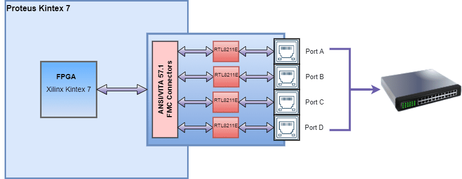
The 4 Port Gigabit Ethernet FMC Module’s Gigabit Ethernet PHY chips (RTL8211E) are connected to the Ethernet MAC on the FPGA using the Reduced Gigabit Media-Independent Interface (RGMII). Regardless of the hardware being utilized, RGMII offers a media-independent interface to ensure compatibility between MAC and PHY.
Supported Numato boards:
Quad Port Concurrent Echo Server example:
Let’s look at a 4-Port Concurrent Echo Server example done on a Numato Lab Proteus Kintex 7 FPGA Board,
It includes a MicroBlaze-based design containing 4 Xilinx AXI Ethernet Subsystem IPs that are configured with AXI DMA IPs and developing a 4 Port Concurrent Echo Server based on FreeRTOS lwIP Echo server template. The template offered by Vitis is only intended for single-port Gigabit Ethernet, thus we must alter it so that it will function for all ports.
Ports A, B, C, and D are the four ports utilized in this example and have unique MAC addresses and IP addresses for each port.
Provided MAC addresses,

Port A    ->   0x00, 0x0a, 0x35, 0x00, 0x01, 0x02
Port B    ->   0x00, 0x0a, 0x35, 0x00, 0x01, 0x03
Port C    ->   0x00, 0x0a, 0x35, 0x00, 0x01, 0x04
Port D    ->   0x00, 0x0a, 0x35, 0x00, 0x01, 0x05

Provided IP addresses,

Port A    ->   192 . 168 . 1 . 10
Port B    ->   192 . 168 . 1 . 11
Port C    ->   192 . 168 . 1 . 12
Port D    ->   192 . 168 . 1 . 13
The hardware setup is done by connecting a 4 port Gigabit Ethernet FMC module to the Numato Lab Proteus Kintex 7 FPGA Board using the FMC connectors. Likewise to establish ethernet communication connect the RJ45 connectors of 4 port Gigabit Ethernet FMC module to the Gigabit switch and make sure that Gigabit Switch and Host PC are connected.
Once auto-negotiation is complete and the echo server on the required port has started, open a telnet session with IP Address corresponding to the port, and the corresponding echo port.
The demo shows the case when initially only ports A and D of 4 port Gigabit Ethernet FMC module are connected to the switch, and then port B and later port C is connected.

You can also ping the ports at their respective IP addresses. Open a command prompt, and you can ping any port using the command `ping <IP address>`. For eg. ping 192.168.1.10 for port A.