Digitization using FMCADCX002
The FMCADCX002 includes 2 Analog Device AD7616 ICs. A total of 32 analog input channels are provided by each AD7616 IC’s 16-channel, 16-bit, dual simultaneous sampling ADC with a sampling rate of up to 1 MSPS.
The AD7616 runs on a single 5 V supply and can handle genuine bipolar input signals of ±10 V, ±5 V, and ±2.5 V while sampling at throughput rates of up to 1 MSPS per channel pair with 90.5 dB SNR. 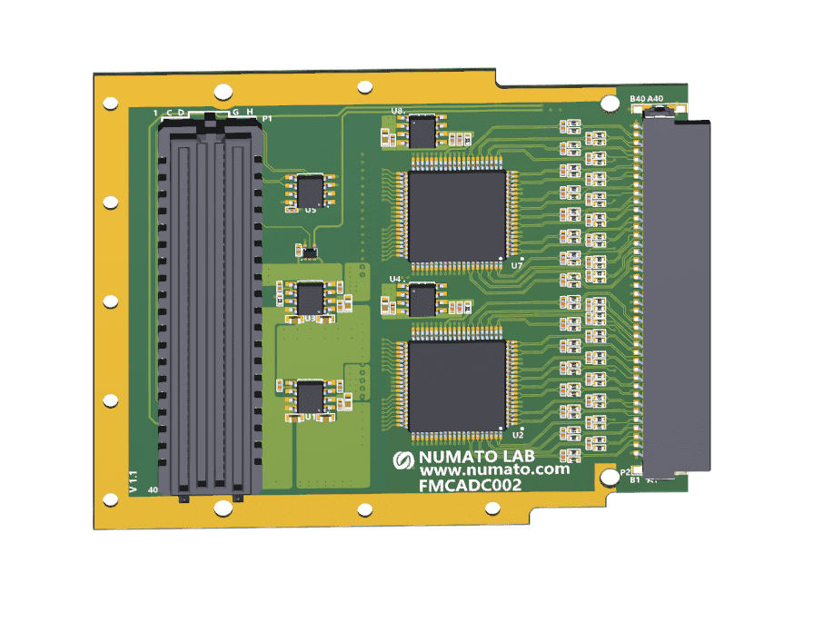
Numato Lab FMCADCX002 ADC Breakout Board with MMCX connectors (Manufacturer Part Number: 0734151471) is to be used along with this module to provide analog inputs.
Supported Numato Lab Boards:
- Numato Lab HSFPX002 Artix 7 FPGA Board
- Numato Lab Nereid Kintex 7 FPGA Board
- Numato Lab Proteus Kintex 7 FPGA Board
- Numato Lab Tagus Artix 7 FPGA Board
FMCADCX002 digitization example:
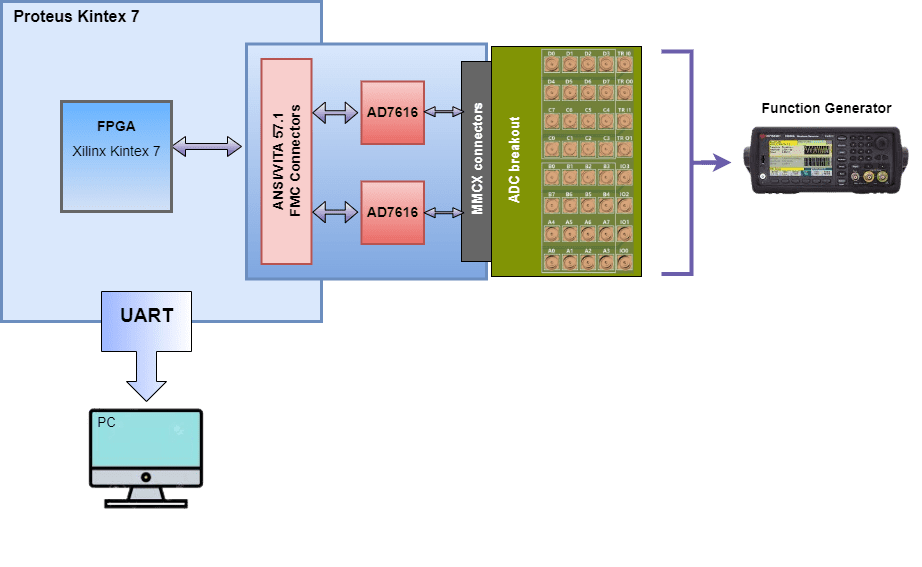
The above block design shows the hardware configuration, in which the FMCADCX002 is linked to the Numato Lab Proteus Kintex 7 FPGA Board through the FMC connections, which contain the 2 AD7616 ICs. To access the function generator’s output, a separate ADC breakout is used.
The AD7616 IC contains 2 ADC devices, which sample the signals simultaneously. The Ad7616 device includes a configuration and control interface. There are registers inside the device that can be programmed and can use those registers to define the device’s behavior.
Considering a serial-2-wire example, the AD7616 device will reads values from the function generator through A0 and B0 of ADC1, which digitizes the analog data and sends them to the FPGA. Once the digitized value reaches the FPGA, it is converted to floating values. In this example, the upper and lower limits are +1.75 and -1.75, respectively, although any value within the range is acceptable.
Additionally, the analog values are interfaced with the FPGA’s RGB LED, which will display different colors dependent on the upper and lower limits of channels 1 and 2.
With-in Limits --> LEDs off
Channel 1 crossed the Upper limit --> RED
Channel 2 crossed the Upper limit --> BLUE
Channel 1 & 2 crossed Upper limit --> MAGENTA
Channel 1 crossed the Upper limit & channel 2 crossed the lower limit --> YELLOW
Channel 1 crossed the lower limit & channel 2 crossed the Upper limit --> GREEN
Channel 1 & 2 crossed lower limit --> CYAN
Channel 1 crossed the lower limit --> WHITE
Channel 2 crossed the lower limit --> LEDs off
After selecting the channel to be tested, analog readings can be observed at that channel.
FMCADCX002 serial-1-wire sample project is provided on the FMCADCX002 product page.