Introduction
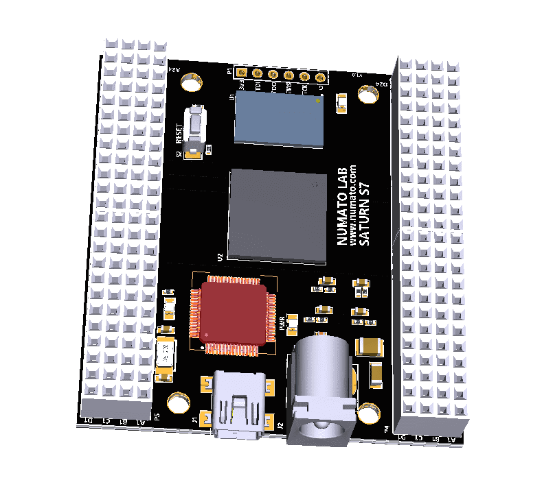
Saturn S7 is an upgraded version of Saturn S6 FPGA development board. It is an easy to use FPGA Development board featuring Spartan 7 FPGA. It was created specifically for the development and integration of FPGA-based features into other designs. It is pin compatible with many other FPGA development boards such as Narvi S7, Spartan S6 etc… Saturn S7 is a great platform for implementing Soft processors such as Microblaze to make it a complete embedded platform. The USB 2.0 host interface based on popular FT2232H offers high bandwidth data transfer and board programming without the need for any external programming adapters. Saturn S7 provides the user with the flexibility of adding their own peripherals through IO Expansion Headers. Additional external reset pin, help the designers to synchronize the signal.
Board Features
- Pin compatible with Narvi Spartan 7 FPGA Board, Saturn Spartan 6 FPGA Module, Skoll Kintex 7 FPGA Module, Neso Artix 7 FPGA Module, Styx Zynq 7020 FPGA Module, and Telesto MAX10 FPGA Module and offers a seamless upgrade path.
- Device: Xilinx Spartan 7 FPGA (XC7S50-CSGA324)
- DDR3: 2Gb DDR3 (MT41J128M16HA-125:K or equivalent)
- Flash memory: 128 Mb Quadbit SPI flash memory (N25Q128A13ESE40E)
- 100MHz CMOS oscillator
- High-Speed USB 2.0 interface for Onboard flash programming. FT2232H Channel A is dedicated to SPI Flash /JTAG Programming. Channel B can be used for custom applications.
- Onboard voltage regulators for single-power rail operation
- FPGA configuration via JTAG and USB
- Maximum IOs for user-defined purposes
- FPGA – 130 IOs
- FT2232H – 8 IOs
Applications
- Product Prototype Development
- Accelerated computing integration
- Development and testing of custom-embedded processors
- Signal Processing
- Communication devises development
- An educational tool for Schools and Universities
How to use Saturn Spartan 7 FPGA Module
The following sections describe in detail how to use this module.
Hardware Accessories Required
For easy and fast installation, you may need the following items along with the Saturn S7 module.
- USB A to Mini B cable
- DC Power supply
- A Xilinx Platform Cable USB II compatible JTAG programmer (optional)
Connection Diagram
The following connection diagram should be used for reference only. The schematics are available at the end of this document for detailed information.
USB Interface
The onboard high-speed USB controller helps a PC/Linux/Mac computer to communicate with this module. Use a USB A to Mini B cable to connect with a PC.
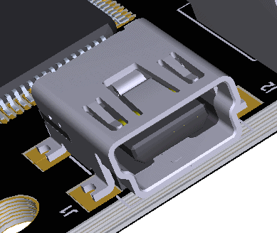
By default, the module is powered by USB so make sure not to overcrowd unpowered USB hubs (the picture on the right shows the Mini B connector)
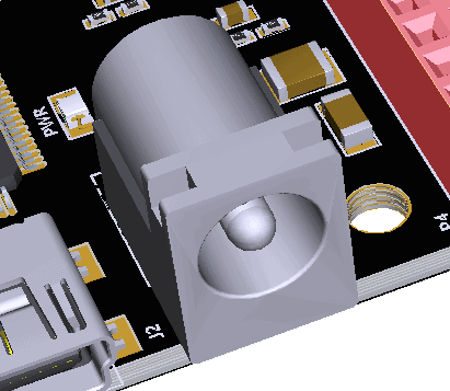
DC Power Supply
The board is configured to use power from the DC power supply by connecting it to the External DC Jack. Please refer to the marking on the board for more details. The external power supply should be in the range of +7 to +12V, with a sufficient current rating.
JTAG Connector
JTAG connector allows the FPGA’s JTAG registers to be accessed using a JTAG cable, compatible with Xilinx Platform Cable USB. Use this header, to attach a JTAG cable for programming and debugging.
Reset Button and LED
Saturn S7 features a Push-button S2 normally used as a “Reset” signal for designs running on FPGA. Push-button S2 is connected to FPGA pin T14. Push-button S2 is active-high. This push button can also be used for any other input and is not limited to being used as a Reset signal.
Saturn S7 also features a general-purpose LED D6 which can be used in the RTL design as per requirement. LED D6 is connected to FPGA pin G13. LED D6 is active-low.
GPIOs
This device is equipped with a maximum of 130 user IO pins that can be used for various custom applications. All user IOs are length matched and can be used as differential pairs.
Header P4
Pin No. On The Header GPIO Pin Name Spartan-7 (CSGA324) Pin No. Pin No. On The Header GPIO Pin Name Spartan-7 (CSGA324) Pin No. Pin No. On The Header GPIO Pin Name Spartan-7 (CSGA324) Pin No. Pin No. On The Header GPIO Pin Name Spartan-7 (CSGA324) Pin No.
A1 GND B1 VCC3V3 C1 VIN D1 GND
A2 GPIO_1_N A14 B2 GPIO_1_P B14 C2 GPIO_4_N A16 D2 GPIO_4_P B16
A3 GPIO_28_N A9 B3 GPIO_28_P A10 C3 GPIO_5_N A17 D3 GPIO_5_P B17
A4 GPIO_21_N C14 B4 GPIO_21_P C13 C4 GPIO_3_N A15 D4 GPIO_3_P B15
A5 GPIO_25_N A11 B5 GPIO_25_P B11 C5 GPIO_20_N A13 D5 GPIO_20_P B13
A6 GPIO_23_N D12 B6 GPIO_23_P E12 C6 GPIO_33_N G6 D6 GPIO_33_P H6
A7 GPIO_14_N D6 B7 GPIO_14_P E6 C7 GPIO_26_N F5 D7 GPIO_26_P G5
A8 GPIO_8_N A4 B8 GPIO_8_P A5 C8 GPIO_12_N C7 D8 GPIO_12_P D7
A9 GPIO_15_N D5 B9 GPIO_15_P E5 C9 GPIO_13_N A6 D9 GPIO_13_P B7
A10 GPIO_7_N B5 B10 GPIO_7_P C5 C10 NC D10 NC
A11 NC B11 NC C11 GPIO_6_N A7 D11 GPIO_6_P A8
A12 NC B12 NC C12 GPIO_18_N E4 D12 GPIO_18_P F4
A13 GND B13 GND C13 GND D13 GND
A14 NC B14 NC C14 GPIO_19_N A2 D14 GPIO_19_P A3
A15 GPIO_2_N B2 B15 GPIO_2_P C2 C15 GPIO_27_N F1 D15 GPIO_27_P F2
A16 GPIO_11_N D1 B16 GPIO_11_P E1 C16 GPIO_10_N B1 D16 GPIO_10_P C1
A17 NC B17 NC C17 NC D17 NC
A18 GPIO_16_N B4 B18 GPIO_16_P C4 C18 GPIO_17_N B3 D18 GPIO_17_P C3
A19 NC B19 NC C19 GPIO_30_N G1 D19 GPIO_30_P G2
A20 GPIO_22_N D2 B20 GPIO_22_P E2 C20 GPIO_24_N E3 D20 GPIO_24_P F3
A21 GPIO_31_N H4 B21 GPIO_31_P H5 C21 GPIO_32_N J1 D21 GPIO_32_P J2
A22 GPIO_29_N H2 B22 GPIO_29_P H3 C22 GPIO_9_N J3 D22 GPIO_9_P J4
A23 GND B23 GND C23 GND D23 GND
A24 VCC3V3 B24 VCC3V3 C24 VCC3V3 D24 VCC3V3
Header P5
Pin No. On The Header GPIO Pin Name Spartan-7 (CSGA324) Pin No. Pin No. On The Header GPIO Pin Name Spartan-7 (CSGA324) Pin No. Pin No. On The Header GPIO Pin Name Spartan-7 (CSGA324) Pin No. Pin No. On The Header GPIO Pin Name Spartan-7 (CSGA324) Pin No.
A1 BCBUS0* B1 BCBUS1 C1 VCC3V3 D1 GND
A2 BCBUS2 B2 BCBUS3 C2 GPIO_46_P C17 D2 GPIO_46_N B18
A3 BCBUS4 B3 BCBUS5 C3 GPIO_47_P D16 D3 GPIO_47_N D17
A4 BCBUS6 B4 BCBUS7 C4 GPIO_49_P F18 D4 GPIO_49_N E18
A5 GPIO_37_P D18 B5 GPIO_37_N C18 C5 GPIO_54_P C12 D5 GPIO_54_N C11
A6 GPIO_36_P E14 B6 GPIO_36_N E15 C6 GPIO_41_P J13 D6 GPIO_41_N J14
A7 GPIO_35_P G16 B7 GPIO_35_N G17 C7 GPIO_44_P H18 D7 GPIO_44_N G18
A8 GPIO_34_P F14 B8 GPIO_34_N F15 C8 GPIO_48_P E16 D8 GPIO_48_N E17
A9 GPIO_50_P H16 B9 GPIO_50_N H17 C9 V_P J10 D9 V_N K9
A10 GPIO_51_P K14 B10 GPIO_51_N J15 C10 TMS T9 D10 TDI R9
A11 GPIO_52_P R15 B11 GPIO_52_N T15 C11 TCK D9 D11 TDO T8
A12 GND B12 GND C12 GND D12 GND
A13 GND B13 GND C13 GND D13 GND
A14 GPIO_64_P U16 B14 GPIO_64_N V17 C14 GPIO_43_P N15 D14 GPIO_43_N P16
A15 GPIO_42_P R16 B15 GPIO_42_N R17 C15 GPIO_40_P K16 D15 GPIO_40_N J16
A16 GPIO_62_P P14 B16 GPIO_62_N P15 C16 GPIO_39_P H15 D16 GPIO_39_N G15
A17 GPIO_63_P U15 B17 GPIO_63_N V16 C17 GPIO_61_P U17 D17 GPIO_61_N U18
A18 GPIO_56_P U12 B18 GPIO_56_N V13 C18 GPIO_45_P H13 D18 GPIO_45_N H14
A19 GPIO_59_P U11 B19 GPIO_59_N V12 C19 GPIO_57_P T12 D19 GPIO_57_N T13
A20 GPIO_58_P R11 B20 GPIO_58_N T11 C20 GPIO_38_P F13 D20 GPIO_38_P E13
A21 GPIO_60_P P13 B21 GPIO_60_N R13 C21 GPIO_53_P C10 D21 GPIO_53_P C9
A22 GPIO_65_P M14 B22 GPIO_65_N N14 C22 GPIO_55_P V14 D22 GPIO_55_P V15
A23 INIT_B U8 B23 VCC3V3 C23 PROGRAM_B R8 D23 VCC3V3
A24 GND B24 GND C24 GND D24 GND
* BCBUS0 – BCBUS7 are pins of FTDI FT2232H Dual-Channel USB device.
FT2232H - Spartan-7 (CSGA324) FPGA Connection Details
FTDI Pin No. Pin Function (245 FIFO) Spartan 7 (CSGA324) Pin No.
38 FTDI-D0 L13
39 FTDI-D1 N13
40 FTDI-D2 L17
41 FTDI-D3 L18
43 FTDI-D4 M17
44 FTDI-D5 M18
45 FTDI-D6 M16
46 FTDI-D7 N18
48 FTDI-RXF# P18
52 FTDI-TXE# P17
53 FTDI-RD# R18
54 FTDI-WR# T18
55 FTDI-SIWUA L16
57 FTDI-CLKOUT R14
58 FTDI-OE# R12
Driver Installation
Windows
This product requires a driver to be installed for proper functioning when used with Windows. The Numato Lab Saturn S7 driver can be downloaded from here. When the driver installation is complete, the module should appear in Tenagra FPGA System Management Software as Saturn Spartan 7 FPGA Module.
Linux
The Linux ships with the drivers required for Saturn S7. It should be enough to run the following two commands in the terminal:
>> sudo modprobe ftdi_sio
>> echo 2a19 100F > /sys/bus/usb-serial/drivers/ftdi_sio/new_id
Generating Bitstream Using Vivado
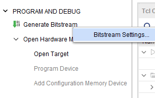
The bitstream can be generated for Saturn S7 in Vivado by following the steps below:
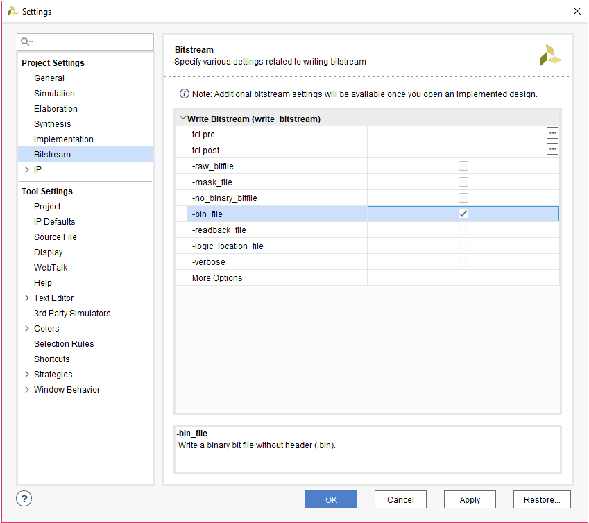
Step 1: It is recommended to generate a .bin bitstream file along with a .bit bitstream file. Click “Bitstream Settings”.
Step 2: Select the “-bin_file*” option in the dialog window and Click OK.
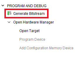
Step 3: Finally click “Generate Bitstream”.
Programming Saturn Using JTAG
Saturn Spartan 7 FPGA Module features an onboard JTAG connector which facilitates easy reprogramming of SRAM and onboard SPI flash through a JTAG programmer like “Xilinx Platform cable USB”. The following steps illustrate how to program FPGA on Saturn using JTAG.
Step 1: By using a JTAG cable, connect Xilinx platform cable USB to Saturn and power it up.
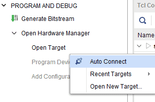
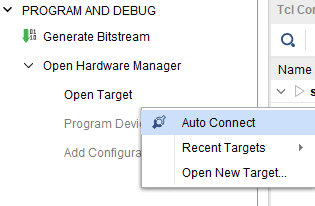
Step 2: Open the Vivado project and open the target by clicking on the “Open Target” in “Open Hardware Manager” in the “Program and Debug” section of the Flow Navigator window. Select “Auto Connect”.
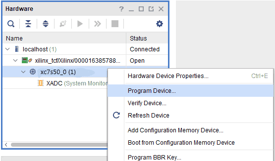
Step 3: If the device is detected successfully, then select “Program Device” after right-clicking on the target device “xc7s50_0 (1)” as shown below.
Step 4: In the dialog window which opens up, Vivado automatically chooses the correct bitstream file if the design was synthesized, implemented and bitstream generated successfully. If needed, browse to the bitstream which needs to be programmed to FPGA. Finally, click “Program”.
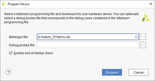
As soon as “Program” is clicked, a green-colored DONE LED (D1) on Saturn should light up, indicating that the programming process is going on. This LED will turn off when the configuration is complete.
Generating Memory Configuration File for Saturn S7 using Vivado
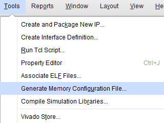
Step 1: Open Xilinx Vivado Hardware Manager. Connect the board, click “Generate Memory Configuration File….” from the “Tools” menu. “Write Memory Configuration File” pop up window will open.
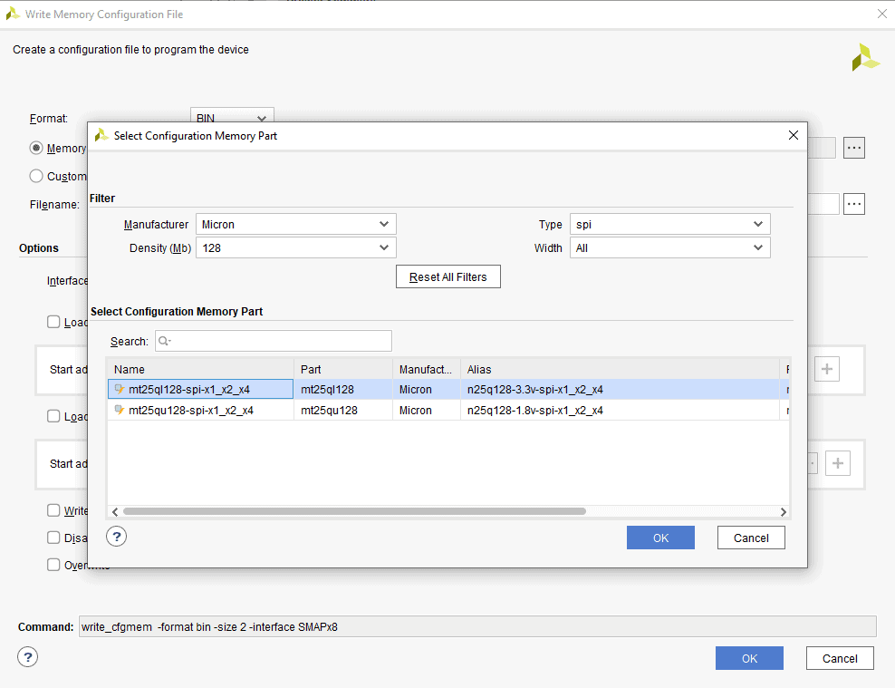
Step 2: Select the ‘Format’ and Configuration Memory Part as shown below. Choose the format as MCS/BIN/HEX depending on your requirement. Now, click “OK”.
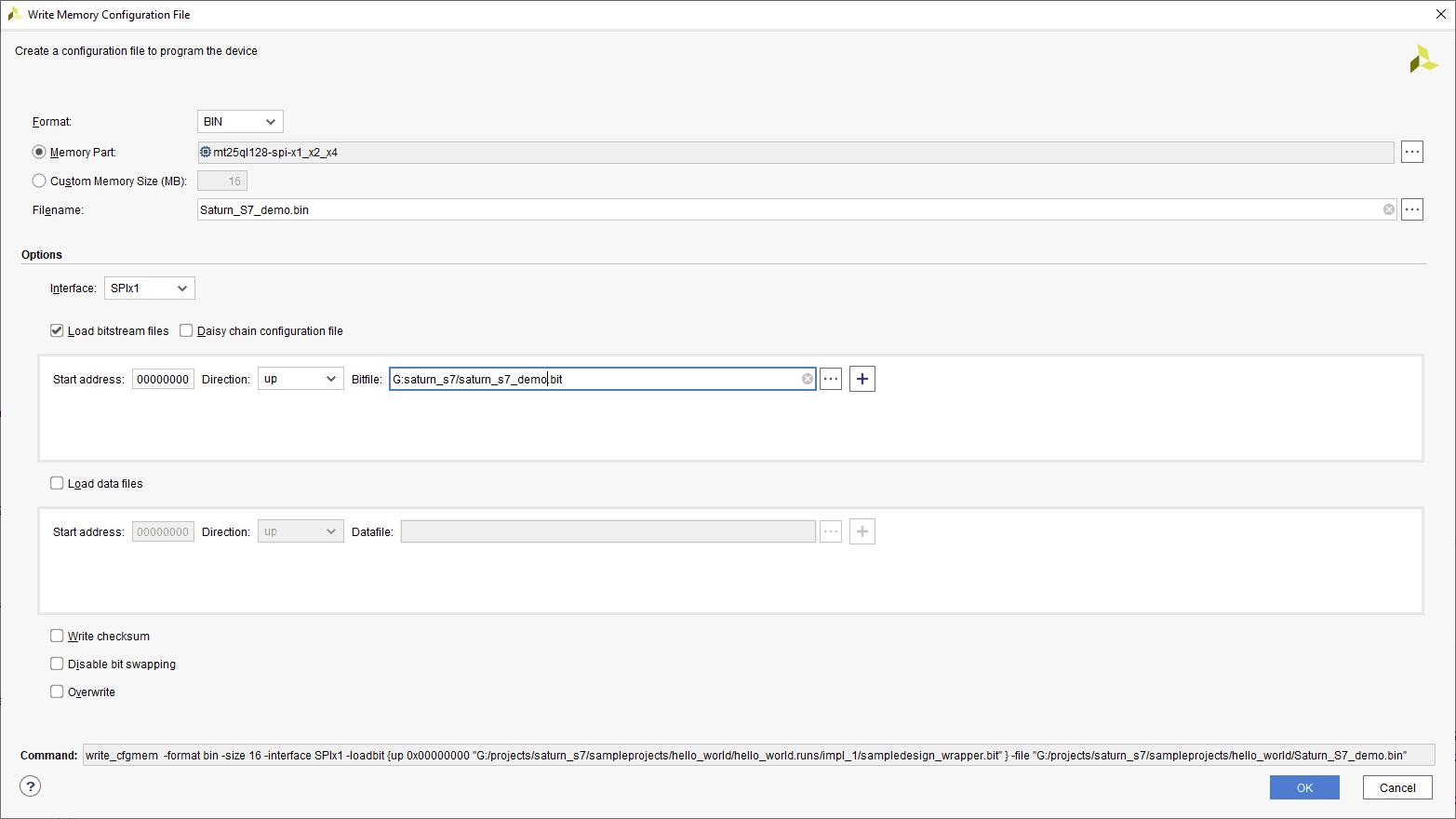
Step 3: Browse to the path where you wish to save the Configuration File and type the file name as “Saturn_S7_demo.bin” (or any name as per your wish/requirement) to save the memory configuration file (the format of the file may change depending on your “Format”). Select the “Load bitstream files” under the “Options” tab and browse to the “.bit” file we already generated then click “OK” to generate the memory configuration file.
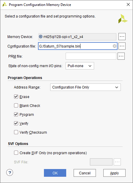
Programming QSPI Flash using Vivado
A .bin or .mcs file is required for programming Saturn’s onboard QSPI flash.
Step 1: Open the Vivado project and open the target by clicking on the “Open Target” in “Open Hardware Manager” in the “Program and Debug” section of the Flow Navigator window. Select “Auto Connect”.
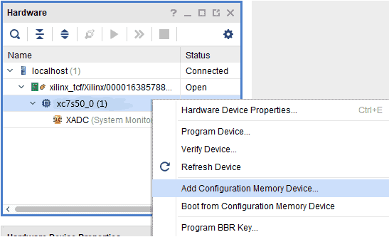
Step 2: If the device is detected successfully, then select “Add Configuration Memory Device” after right-clicking on the target device “xc7s50_0” as shown below.
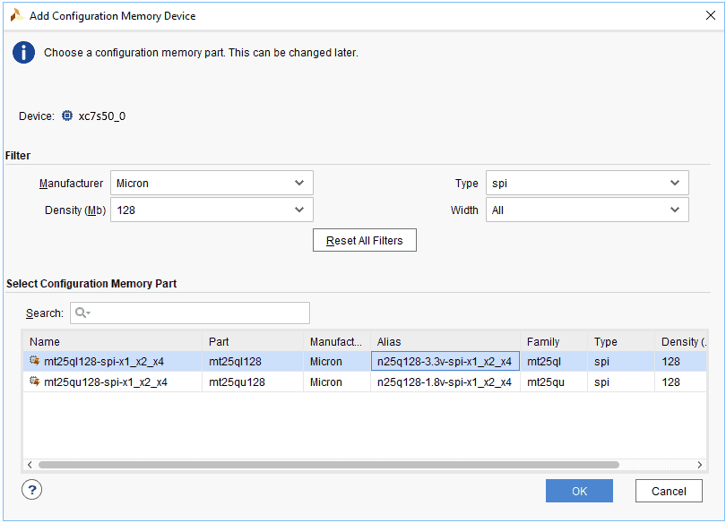
Step 3: Select the memory device “mt25ql128-spi-x1_x2_x4 (which is equivalent to n25q128-3.3v-spi-x1_x2_x4)”, then click OK.
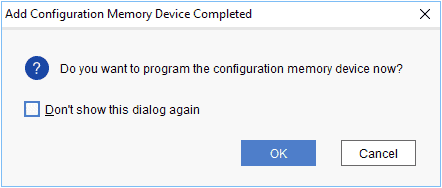
Step 4: After completion of Step 3 the following dialog box will open. Click OK.
Step 5: Browse to the working .bin file or the .mcs file (whichever is applicable) and click OK to program as shown below. If programming is successful, a confirmation message will be displayed.
Programming Saturn S7 Using Tenagra
For steps on how to program Saturn S7 using Tenagra, refer to the Getting started with Tenagra FPGA System Management Software article.
Technical Specifications
[table “459” not found /]
Mechanical Dimensions
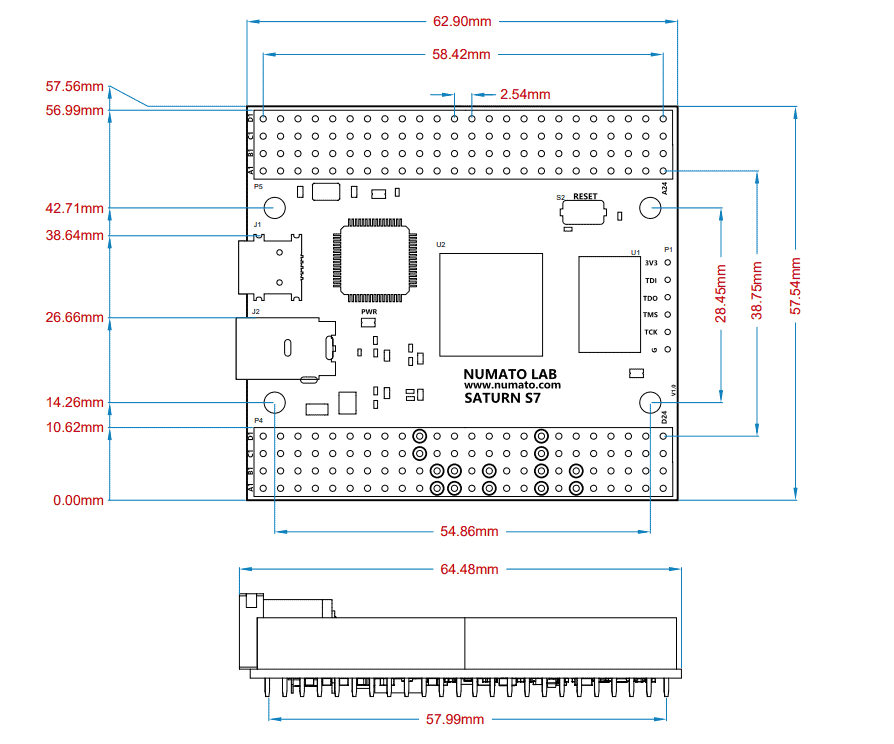
Help Guide Powered by Documentor Saturn Spartan 7 FPGA Module
0 views December 13, 2022 gayathri-ks 0
