Introduction
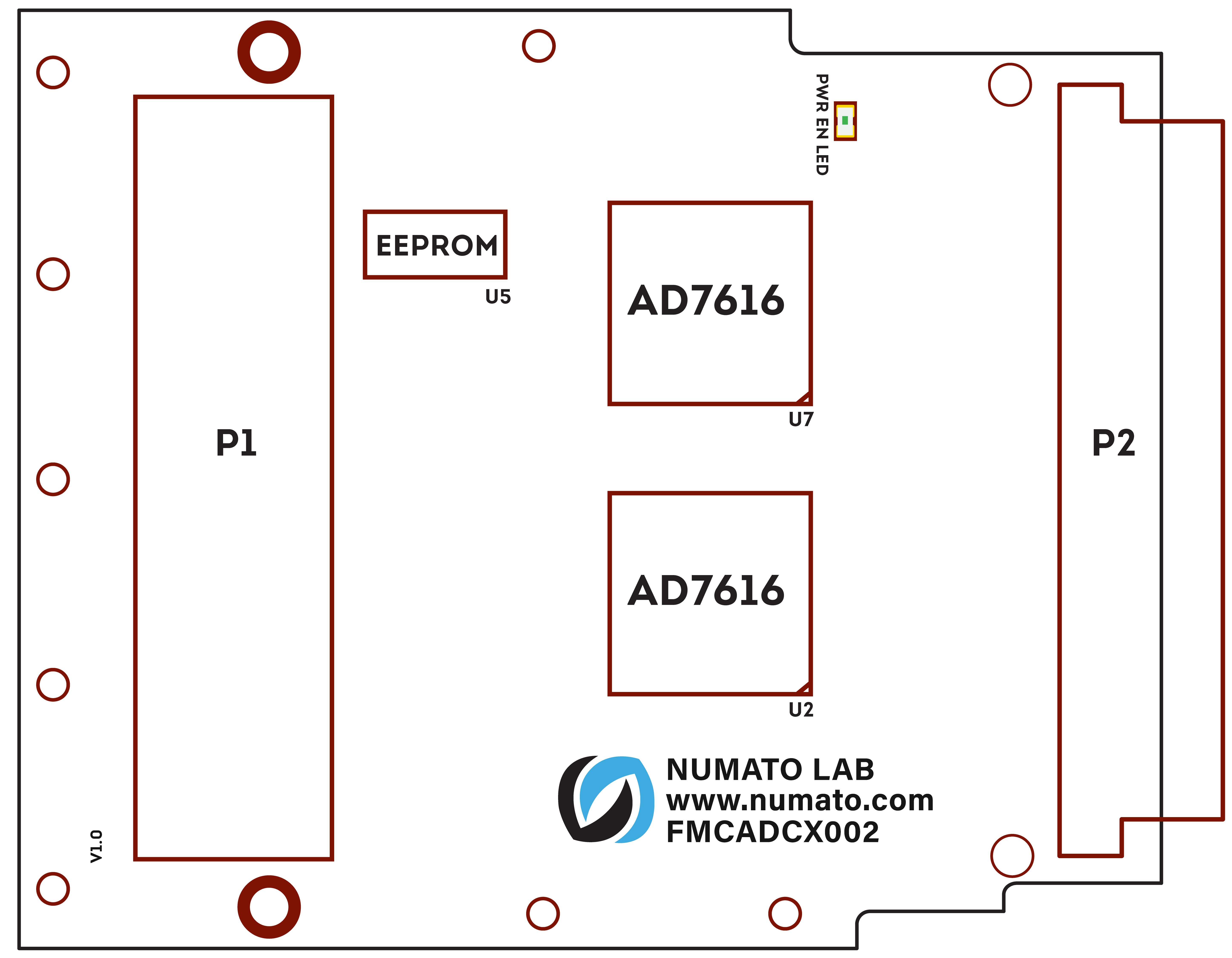
The Numato Lab FMCADCX002 ADC Expansion Module features two Analog Devices AD7616 ICs. Each IC has a 16 channel, 16-bit, dual simultaneous sampling ADC with a sampling rate of up to 1 MSPS, thus providing a total of 32 analog input channels. The AD7616 is designed to support communications applications where low cost, small size, wide bandwidth, and versatility are desired. This module is designed to be used with Numato Lab’s FPGA boards featuring FMC connectors, and can additionally be used with any FPGA board supporting the FMC LPC connector. Numato Lab FMCADCX002 ADC Breakout Board with MMCX connectors (Manufacturer Part Number: 0734151471) is to be used along with this module to provide analog inputs.
Applications
- Digital Instrumentation
- Product prototyping
- Low-Cost Digital Oscilloscopes
- Data acquisition
- Electronic test and measurement equipment
Board Features
- FMC LPC connector for mating with compatible FPGA carrier cards
-
Two dual simultaneous sampling AD7616 ICs
-
32 Analog input channels with selectable input range (±10 V, ±5 V, ±2.5 V)
-
16-bit resolution with 1 MSPS maximum sampling rate
- 2 trigger inputs, 2 trigger outputs and 4 IOs
- No external power supply is needed. Uses 12V supplies from Carrier boards through FMC LPC connector
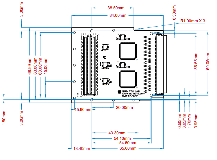
- Dimension: 84.01mm x 68.99mm
How to use the module
The following section describes how to use this module.
Compatible FPGA Boards
Along with the module, you may use any of the boards below, or any ANSI/VITA 57.1 Standard Compliant FMC FPGA boards can be used.
Connection Details
Pin Details of FMC LPC connector – Header P1
| SL.No | Signal Details | FMC Pin Location | Trace Length(mm) |
|---|---|---|---|
| 1 | TRIG_OUT_0 | H19 | 128.25 |
| 2 | TRIG_OUT_1 | H20 | 126.02 |
| 3 | TRIG_IN_0 | G19 | 130.59 |
| 4 | TRIG_IN_1 | D20 | 124.60 |
| 5 | PG_C2M | D1 | 31.67 |
| 6 | IO_0 | D18 | 120.86 |
| 7 | IO_1 | D17 | 119.10 |
| 8 | IO_2 | G18 | 123.22 |
| 9 | IO_3 | C18 | 116.93 |
| 10 | GA0 | C34 | 78.82 |
| 11 | GA1 | D35 | 81.01 |
| 12 | ADC_SDA | C31 | 64.89 |
| 13 | ADC_SCL | C30 | 63.97 |
| 14 | ADC_0_DB0 | G24 | 37.92 |
| 15 | ADC_0_DB1 | G25 | 37.92 |
| 16 | ADC_0_DB2 | H25 | 37.92 |
| 17 | ADC_0_DB3 | D26 | 37.92 |
| 18 | ADC_0_DB4/SER1W | H26 | 37.92 |
| 19 | ADC_0_DB5/CRCEN | G27 | 37.92 |
| 20 | ADC_0_DB6 | H28 | 37.92 |
| 21 | ADC_0_DB7 | H29 | 37.92 |
| 22 | ADC_0_DB8 | G28 | 37.92 |
| 23 | ADC_0_DB9 | G30 | 37.92 |
| 24 | ADC_0_DB10/SDI | H31 | 37.92 |
| 25 | ADC_0_DB11/SDOB | G31 | 37.92 |
| 26 | ADC_0_DB12/SDOA | H32 | 37.92 |
| 27 | ADC_0_DB13 | G33 | 37.92 |
| 28 | ADC_0_DB14 | H34 | 37.92 |
| 29 | ADC_0_DB15 | H35 | 37.92 |
| 30 | ADC_0_WR/BURST | G34 | 37.92 |
| 31 | ADC_0_SCLK/RD | G36 | 37.95 |
| 32 | ADC_0_RESET | D24 | 43.85 |
| 33 | ADC_0_REFSEL | H23 | 37.38 |
| 34 | ADC_0_CS | H37 | 38.01 |
| 35 | ADC_0_CONVST | G37 | 40.20 |
| 36 | ADC_0_BUSY | H38 | 40.03 |
| 37 | ADC_1_DB0 | D8 | 39.01 |
| 38 | ADC_1_DB1 | G6 | 39.01 |
| 39 | ADC_1_DB2 | H7 | 39.01 |
| 40 | ADC_1_DB3 | H10 | 39.01 |
| 41 | ADC_1_DB4/SER1W | H11 | 39.02 |
| 42 | ADC_1_DB5/CRCEN | D11 | 39.01 |
| 43 | ADC_1_DB6 | D12 | 39.01 |
| 44 | ADC_1_DB7 | G12 | 39.01 |
| 45 | ADC_1_DB8 | G13 | 39.01 |
| 46 | ADC_1_DB9 | H13 | 39.01 |
| 47 | ADC_1_DB10/SDI | D14 | 39.01 |
| 48 | ADC_1_DB11/SDOB | H14 | 39.01 |
| 49 | ADC_1_DB12/SDOA | G15 | 39.01 |
| 50 | ADC_1_DB13 | H16 | 39.01 |
| 51 | ADC_1_DB14 | G16 | 39.01 |
| 52 | ADC_1_DB15 | H17 | 39.01 |
| 53 | ADC_1_SCLK/RD | H22 | 39.01 |
| 54 | ADC_1_WR/BURST | D23 | 39.01 |
| 55 | ADC_1_RESET | C10 | 57.45 |
| 56 | ADC_1_REFSEL | C11 | 58.66 |
| 57 | ADC_1_CS | G22 | 40.17 |
| 58 | ADC_1_CONVST | D21 | 45.31 |
| 59 | ADC_1_BUSY | G21 | 38.98 |
Pin Details of 40×2 connector – Header P2
Numato Lab FMCADCX002 ADC Breakout Board is to be connected to header P2 for providing analog inputs.
| SL.No | Signal Details | 40x2 Connector Pin location | Trace Length(mm) |
|---|---|---|---|
| 1 | ADC_0_B0 | B2 | 9.198 |
| 2 | ADC_0_B1 | B3 | 5.389 |
| 3 | ADC_0_B2 | B4 | 8.863 |
| 4 | ADC_0_B3 | B5 | 5.099 |
| 5 | ADC_0_B4 | B6 | 8.586 |
| 6 | ADC_0_B5 | B7 | 5.1 |
| 7 | ADC_0_B6 | B8 | 8.813 |
| 8 | ADC_0_B7 | B9 | 5.332 |
| 9 | ADC_0_A0 | B10 | 10.923 |
| 10 | ADC_0_A1 | B11 | 6.833 |
| 11 | ADC_0_A2 | B12 | 6.054 |
| 12 | ADC_0_A3 | B13 | 10.227 |
| 13 | ADC_0_A4 | B14 | 5.889 |
| 14 | ADC_0_A5 | B15 | 9.505 |
| 15 | ADC_0_A6 | B16 | 5.735 |
| 16 | ADC_0_A7 | B17 | 9.223 |
| 17 | ADC_1_B0 | B24 | 11.174 |
| 18 | ADC_1_B1 | B25 | 7.241 |
| 19 | ADC_1_B2 | B26 | 6.384 |
| 20 | ADC_1_B3 | B27 | 10.374 |
| 21 | ADC_1_B4 | B28 | 5.658 |
| 22 | ADC_1_B5 | B29 | 9.179 |
| 23 | ADC_1_B6 | B30 | 5.545 |
| 24 | ADC_1_B7 | B31 | 9.294 |
| 25 | ADC_1_A0 | B32 | 9.095 |
| 26 | ADC_1_A1 | B33 | 5.272 |
| 27 | ADC_1_A2 | B34 | 8.759 |
| 28 | ADC_1_A3 | B35 | 5.031 |
| 29 | ADC_1_A4 | B36 | 8.652 |
| 30 | ADC_1_A5 | B37 | 5.098 |
| 31 | ADC_1_A6 | B38 | 8.516 |
| 32 | ADC_1_A7 | B39 | 4.848 |
Technical Specification
| Parameter* | Value | Unit |
|---|---|---|
| Basic Specifications | ||
| EEPROM (24AA025E48T-I/SN) | 2 | Kb |
| Analog Input | ±10 ,±5, ±2.5 | V |
| 2 x Reference Voltage (ADR421ARZ) | 2.5 | V |
| Analog Power (ADM7150ARDZ) | 5.0 | V |
| Digital Power (ADM7150ARDZ) | 3.3 | V |
| MMCX Connector (0734151471) | - | - |


