Introduction

Numato Lab’s 32 Channel USB Pluggable GPIO Module is a great product for controlling electrical and electronic devices remotely from a PC or Mobile Device over USB link. Ease of use and wider operating system compatibility are the primary goals behind this product’s design. Built-in USB to serial conversion allows the module to be used, without any specific knowledge about USB. This simplicity allows use of off-the-shelf Terminal Emulation programs such as Tera term, PuTTY for controlling the module with a simple set of human readable commands. For power users, this module can be controlled by writing programs in various programming languages.
Features:
- 32 TTL (3.3V) compatible GPIOs
- 7 analog inputs with 10-bit resolution (multiplexed with digital IOs)
- USB interface with CDC support. As easy as using a serial port, no USB knowledge required
- All IOs available on easy to plug headers
- Can be powered from USB or external power supply
- Can be controlled by using standard serial console applications or custom applications
Some of the possible uses of this module includes:
- Home Automation
- Lighting Control
- Garden Equipment Control
- Industrial Automation
- Test Fixtures
- DIY and Hobby
This product is compatible with the following operating systems:
- Windows XP and later versions (Windows 7, 8/8.1, 10 and future versions)
- Windows 7 Embedded and later
- Linux
- Mac OS X
- Android
- Or any other operating system that supports USB CDC devices.
And these are some of the languages that can be used for programming:
- C/C++
- Visual Basic (VB6, VB2008, VB2010 express and other editions)
- Visual Basic for Applications (Microsoft Office VBA)
- Perl
- Python
- JAVA
- Android
- Javascript (Node.js)
- And many more…
This module has 32 on board General purpose I/Os multiplexed with 7 Analog Inputs. The analog inputs (multiplexed with GPIOs) can be accessed over USB interface for extended functionality. When connected to PC, the module will appear as a serial port in Windows Device Manager (or a serial tty device in Linux and Mac).
Technical Specifications
| Parameter | Value | Unit |
|---|---|---|
| Number of GPIOs | 32 | |
| Number of analog inputs (Multiplexed with GPIOs) | 7 | |
| Digital circuit power supply voltage (USB or external) | 5 | V |
| Maximum current drawn by digital circuitry | 300 | mA |
| IO Specifications | ||
| Maximum IO source current : IO8 – IO15 | 25 | mA |
| Maximum IO source current: IO21 – IO31 | 8 | mA |
| Maximum IO source current : IO0 – IO7, IO16 – IO20 | 2 | mA |
| Maximum IO sink current : IO8 – IO15 | 25 | mA |
| Maximum IO sink current : IO21 – IO31 | 8 | mA |
| Maximum IO sink current : IO0 – IO7, IO16 – IO20 | 2 | mA |
| GPIO input low voltage | 0.15 | V |
| GPIO input high voltage | 3.3 | V |
| GPIO output low voltage | 0 | V |
| GPIO output high voltage | 3.3 | V |
| ADC Specifications | ||
| Resolution | 10 | bits |
| Full scale range | 0 – VDD | V |
| Reference voltage | VDD | V |
| Recommended Impedance of Analog Voltage Source | 2.5 | KΩ |
| Other Information | ||
| USB Vendor ID | 0x2A19 | |
| USB Product ID | 0x080A | |
* All parameters considered nominal. Numato Systems Pvt. Ltd. reserves the right to modify products without notice.
How to Use 32 Channel USB Pluggable GPIO Module
Using this product is very easy. The USB CDC interface allows this device to be used with most readily available serial terminal software such as Tera Term or HyperTerminal. Below shows some of the software for different operating systems.
- Windows
- PuTTY
- HyperTerminal
- Tera Term
- Linux
- GNU Screen
- PuTTY
- Mac OS X
- Screen Command
- CoolTerm
- goSerial
Components/Tools Required
Along with the module, you may need the items in the list below for easy and fast installation.
1. USB A to B cable
Connection Details
- Connect the device to a USB port on the host system
- Install driver (Only needed for Windows. Driver available for download on the product page.)
- Open the COM port corresponding to the device using a Serial Terminal software
- Enter commands (Very similar to entering commands at DOS prompt or Bash prompt)
- Optionally write a script or application to automate your task
Refer documentation “Driver Installation”
The module is connected to the PC through a USB Type B cable. The digital circuitry is powered from the USB.
An external +5V power is required only if the USB port is unable to supply enough current.
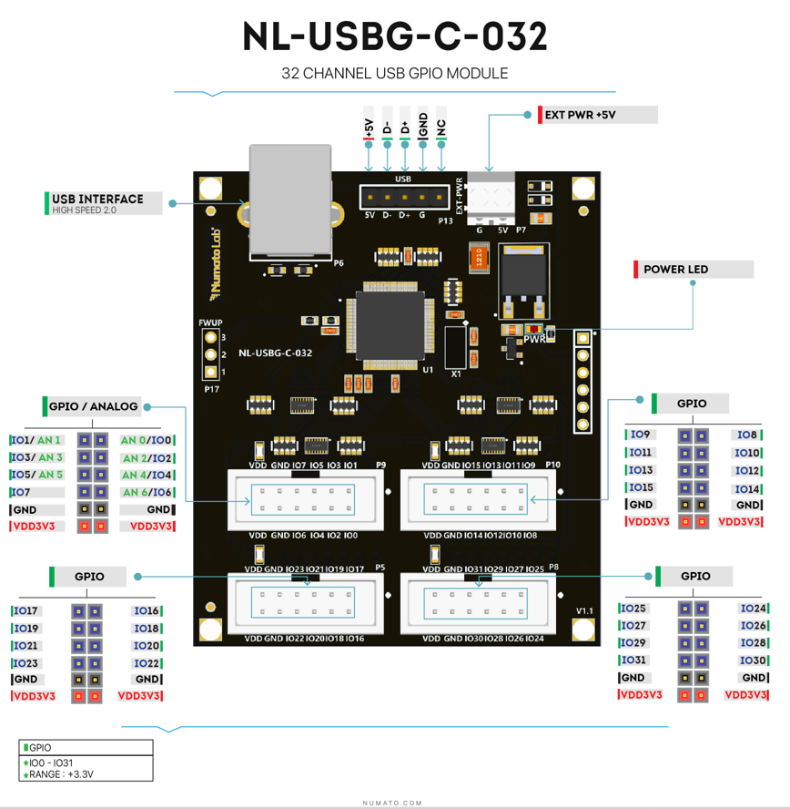
GPIO/Analog Inputs
The module has 32 General Purpose IO pins that can be used for various custom applications. Some of these pins can be used as Analog to Digital Converter inputs as well. All IO pins support 3.3V TTL signals and the ADC input range is 0 to +3.3V. The ADC can acquire analog signal at the resolution of 10 bits per sample. It is recommended to use a series resistor with the GPIO/ADC pins when interfacing with other circuits. A 470 Ohms series resistor is recommended for current limiting when connecting LED to a GPIO.
In contrast to GPIOs Analog inputs can read voltages at any level between 0 to 3.3V volts. It is recommended to use a series resistor to protect the input from stray voltages and spikes. The internal Analog to Digital converter supports 10 bits resolution which is adequate for most applications.
The table below summarizes the GPIO and Analog to Digital Converter input positions on the header P9.
| GPIO | ADC |
|---|---|
| IO0 | ADC0 |
| IO1 | ADC1 |
| IO2 | ADC2 |
| IO3 | ADC3 |
| IO4 | ADC4 |
| IO5 | ADC5 |
| IO6 | ADC6 |
| IO7 | - |
| GND | GND |
| GND | GND |
| VDD | 3.3V |
| VDD | 3.3V |
The table below summarizes the GPIO and Analog to Digital Converter input positions on the header P10.
| GPIO | ADC |
|---|---|
| IO8 | - |
| IO9 | - |
| IO10 | - |
| IO11 | - |
| IO12 | - |
| IO13 | - |
| IO14 | - |
| IO15 | - |
| GND | GND |
| GND | GND |
| VDD | 3.3V |
| VDD | 3.3V |
The table below summarizes the GPIO and Analog to Digital Converter input positions on the header P5.
| GPIO | ADC |
|---|---|
| IO16 | - |
| IO17 | - |
| IO18 | - |
| IO19 | - |
| IO20 | - |
| IO21 | - |
| IO22 | - |
| IO23 | - |
| GND | GND |
| GND | GND |
| VDD | 3.3V |
| VDD | 3.3V |
The table below summarizes the GPIO and Analog to Digital Converter input positions on the header P8.
| GPIO | ADC |
|---|---|
| IO24 | - |
| IO25 | ADC10 |
| IO26 | - |
| IO27 | - |
| IO28 | - |
| IO29 | - |
| IO31 | - |
| IO31 | - |
| GND | GND |
| GND | GND |
| VDD | 3.3V |
| VDD | 3.3V |
Sending Commands
One of the most powerful features of this module is the simple easy to use command set it supports. This command set hides the complex USB protocol and gives a very simple interface to access the features of the module. The following sections give details of the command set and how to use the command set.
The Commands Set
This product supports a very simple command set that is designed to be less cryptic and easy to use manually (using serial terminal emulation programs) or through a program written in many supported languages.
List of currently supported commands.
| No. | Command | Parameters | Usage | Description |
|---|---|---|---|---|
| 1 | ver | none | ver | Returns firmware version |
| 2 | id | get | id get | Reads Module ID |
| set xxxxxxxx | id set 12345678 | Assign ID to the module | ||
| 3 | gpio | set xxx clear xxx | gpio set 000 gpio clear 000 | Control the GPIOs |
| read xxx | gpio read 000 | Read GPIO Input status | ||
| status xxx | gpio status 000 | Read GPIO status | ||
| readall | gpio readall | Read all GPIO status at a time | ||
| writeall xxxxxxxx | gpio writeall ffffffff | Control all GPIOs at a time | ||
| iomask xxxxxxxx | gpio iomask ffffffff | Control GPIOs mask status | ||
| iodir xxxxxxxx | gpio iodir 00000000 | Control GPIOs direction | ||
| notify on notify off | gpio notify on gpio notify off | Control Notify feature | ||
| notify get | gpio notify get | Read Notify Status | ||
| poweron xxxxxxxx xxxxxxxx | gpio poweron 00000000 ffffffff | Control GPIO Power-On IO direction & status respectively | ||
| 4 | adc | read xxx | adc read 000 | Read Analog to Digital Converter input value |
| 5 | info | None | info | Returns GPIO Power-On Direction & Status |
The table below has more detailed information about available commands.
| No. | Command | Usage | Description |
|---|---|---|---|
| 1 | ver | ver | Returns firmware version. |
| 2 | id | id get | Reads the module ID. |
| id set xxxxxxxx | Assign an 8-digit ID to the module, where ‘x’ can be any alphanumeric character. | ||
| 3 | gpio | gpio set xxx | Sets GPIO ‘xxx’ output status to high. gpio set 000 – Sets IO0 to high state xxx can be 000 – 031 |
| gpio clear xxx | Sets GPIO ‘xxx’ output status to low. gpio clear 000 – Sets IO0 to low state xxx can be 000 – 031 |
||
| gpio read xxx | Read the input status present at ‘xxx’. gpio read 007 – Read input status of IO7 and print either ‘1’ or ‘0’ depending on the status xxx can be 000 – 031 |
||
| gpio status xxx | Read the GPIO status present at ‘xxx’ without changing the GPIO to inputs. gpio status 007 – Read status of IO7 and print either ‘1’ or ‘0’ depending on the status xxx = 000 to 031 |
||
| gpio iomask xxxxxxxx | Masks/Unmasks all GPIOs in a single operation. gpio iomask ffff0000 – Masks and/or unmasks GPIO at each bit position according to the bits of the specified hexadecimal value. 0 – To mask the GPIO & 1 – To unmask the GPIO. ‘ffff0000’ – 1111 1111 1111 1111 0000 0000 0000 0000: Masks GPIOs 0 – 15 & unmasks GPIOs 16 - 31. |
||
| gpio iodir xxxxxxxx | Sets direction of all GPIOs as Input/output mode in a single operation. gpio iodir 0000540f – Sets GPIOs as input/output at each bit position according to the bits of the specified hexadecimal value. 0 – To set the GPIO as output mode & 1 – To set the GPIO as input mode. ‘0000540f’ – 0000 0000 0000 0000 0101 0100 0000 1111: Sets GPIO 0,1,2,3,10,12 & 13 as input mode Sets GPIO 4,5,6,7,8,9,11,13,15,16-30 & 31 as output mode. |
||
| gpio readall | Read status of all GPIOs in single operation. gpio readall – Read all GPIO status and print xxxxxxxx. xxxxxxxx is a hexadecimal value, with binary 1 at positions for GPIOs in HIGH and 0 for GPIOs in LOW state. |
||
| gpio writeall xxxxxxxx | Control all GPIOs in single operation. Gpio writeall ffff67a4 – Sets and clears GPIO at each bit position according to the bits of the specified hexadecimal value. 0 – To clear the GPIO & 1 – To set the GPIO ‘ffff67a4’ – 1111 1111 1111 1111 0110 0111 1010 0100: Sets GPIO 2,5,7,8,9,10,13-14,16-30 & 31 Clears GPIO 0,1,4,6,11,12 & 15. Refer Understanding readall/writeall commands for GPIO Modules to know more. |
||
| gpio notify on | This command enables the gpio input change notification. When the gpio notify feature is enabled, changes to the input pins will be detected and a notification is sent to the host. To use notify feature on a GPIO, the GPIO must be set to input mode by using “gpio iodir” command. The GPIO change notification is sent to the host is in the below format. If GPIO change notification is “FFFFFFFE FFFFFFFF FFFFFFFF”, then 1. Current IODIR value is FFFFFFFF which means all GPIOs are set to input mode. 2. Previous GPIO values are FFFFFFFF. 3. Current GPIO values are FFFFFFFE. The GPIO 0 value is changed from logic 1 to 0. This change triggered the device to send this notification. |
||
| gpio notify off | This command disables the gpio input change notification feature. | ||
| gpio notify get | Returns whether Notify feature is enabled or disabled. | ||
| gpio poweron xxxxxxxx xxxxxxxx | This command is to control Power-On GPIO Direction and status in a single operation. gpio poweron ffff0000 000011c5 – Sets GPIOs IO direction and status respectively at each bit position according to the bits of the specified hexadecimal value. IO direction: 0 – To set the GPIO as output mode & 1 – To set the GPIO as input mode. IO status: 0 - To clear the GPIO & 1 - To set the GPIO. ‘ffff0000 000011c5’- (1111 1111 1111 1111 0000 0000 0000 0000) (0000 0000 0000 0000 0001 0001 1100 0101): GPIOs 0-15 are set to output mode & GPIOs 16-31 are set as input mode. GPIO 0,2,6,7,8 & 12 are set to High GPIO 1,3,4,5,9-11,13-14 & 15 are set to Low. |
||
| 4 | adc | adc read xxx | Reads the analog voltage present at the ADC input mentioned. “xxx” stands for the number of ADC input. The response will be a number that ranges from 0 – 1023. Please see examples below. adc read 000 – Reads analog input 0 adc read 004 – Reads analog input 4 xxx can be 000 to 006 |
| 5 | info | info | Returns GPIO Power-On Direction & Status. |
NOTE!
Refer Understanding readall/writeall commands for GPIO Modules to know more.
Accessing the module
32 Channel USB Pluggable GPIO Module allows to communicate through any of the Serial Terminal Emulator Software
using simple easy to use commands mentioned in the command set above.
Refer documentation “Sending Commands to the Numato Lab USB Modules” to know more.
Additional Information
Analog to Digital Converters (ADCs)
7 GPIOs on board do support Analog to Digital Conversion. There is no special command required to execute to switch between analog and digital mode. Executing “adc” command will set the GPIO to analog mode and executing “gpio” command will set the GPIO back to digital mode on the fly. Resolution of the ADC is 10 bits unless otherwise noted. The input voltage range of the ADC is 0 – VDD (this product uses 3.3V power supply, so the range will be 0 – 3.3V). The result will be returned as a number starting at zero and ending at 1023. Zero indicates zero volts at the ADC input and 1023 indicates VDD (3.3V for this product) at ADC input.
GPIO with Switches
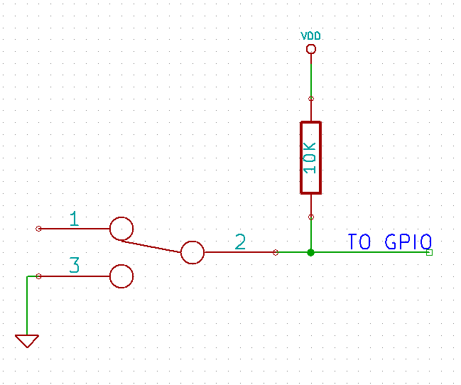 It is possible to read the position of a switch that is connected to a GPIO. A SPST or SPDT switch is recommended to use with GPIOs. Push switches do maintain the contacts closed only for a very short time so using them is discouraged. The fundamental idea of using a switch with GPIO is to have the switch cause a voltage level change at the GPIO pin when pressed. Usually this is achieved by using an external pull-up resistor along with the switch. The pull up resistor is connected between the GPIO and VDD and the switch is connected between the GPIO and ground. When the switch is not pressed, the pull-up resistor will cause the GPIO to stay at VDD voltage level. When the switch is pressed, the GPIO is short circuited to ground and stays at zero voltage. This change in voltage and thus the position of the switch can be read using “gpio read” command.
Frequently Asked Questions (FAQs)
Q. What are the serial parameters I need to use when communicating with this board?
A. Since this module uses USB as the underlying transport mechanism, most of the serial parameters do not affect the communication. You can leave all parameters to any legal value (Eg: 2400, 4800, 9600 etc… for baud rate) except Flow control. Flow control needs to be set to “None”.
Q. Where do I find driver for this product?
A. Visit http://numato.com and navigate to the product page. There will be a link to download windows driver. Linux does not require driver installation since in most cases they are shipped with the driver pre-installed.
Q. Why there is no .sys or .exe file in the Windows driver package I downloaded?
A. This product uses USB CDC driver binary which is already present on Windows. All Windows versions (with the exception of Embedded Editions) has this driver binary installed by default. The .inf and .cat files present in the zip file helps Windows identify the device properly and associate appropriate driver (.sys) to the device
Q. Does this product work with Linux?
A. Yes, this product works with Linux. Please see more details on how to use this product with Linux elsewhere in this document.
Q. Does this product work with Mac OSX?
A. Yes, this product works with Mac OSX. Please see more details on how to use this product with Mac elsewhere in this document.
Q. What are the serial terminal software that this product work with?
A. This product works with a lot of different Serial Terminal software. Some examples can be found elsewhere in this document. Different Serial Terminal software are written by different developers with different purposes in mind. So you may encounter some software that may not work with this product. But usually alternatives are available in most if not all cases.
Q. The GPIO looses its previously set value when trying to read the status. Why it is so?
A. When a gpio is to output a value (high/low), that particular GPIO is put to output mode. When you are trying to read the GPIO, it needs to be put in input mode. In input mode, the GPIO will go to high impedance state and thus looses the previously set value.
Q. I’m using x language for programming. How do I find out if this language can be used to program and control the GPIO module?
A. Find out if the language of interest supports some kind of APIs/Functions/Components for serial communication. If it does, most likely you should be able to use that language with this module.
Q. What is the connector marked as ICSP on this module?
A. This connector is used to program the on-board microcontroller. This connector is primarily intended for factory use.
Q. I need a customized version of this product, can Numato do the customization for me?
A. Yes, we can definitely do customization but there may be minimum order requirements depending on the level of customization required. Please write to sales@numato.com for a quote.
Q. Where can I buy this product?
A. All Numato products can be ordered directly from our web store http://www.numato.com. We accept major credit cards and Paypal and ship to almost all countries with a few exceptions. We do have distributors in many countries where you can place your order. Please find the current list of distributors at http://numato.com/distrib.
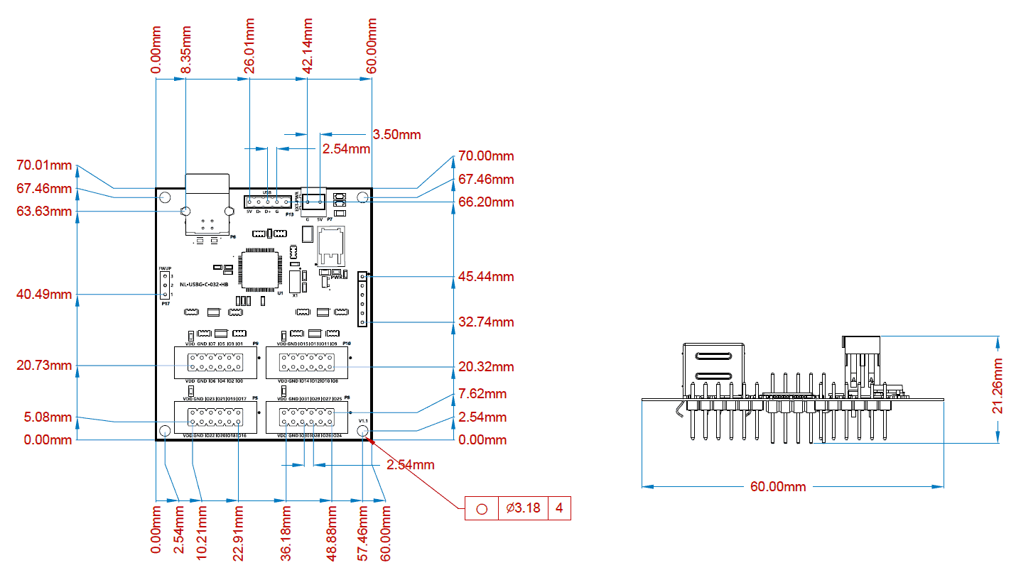
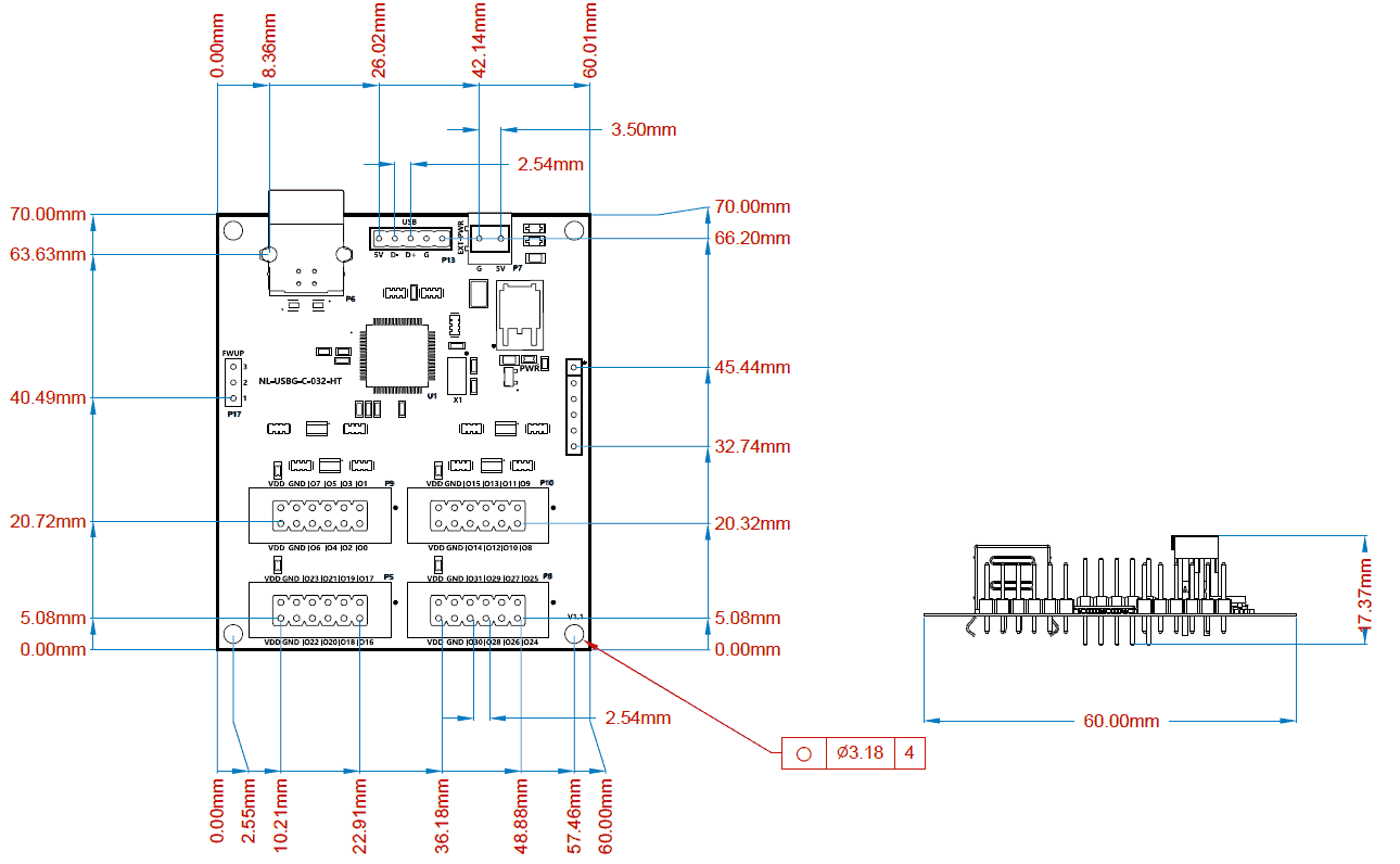
Mechanical Dimensions
Header On Top :
Header On Bottom :