Introduction
Numato Lab’s 4 channel Ethernet DAQ (4ADC-4DAC) Module offers a convenient solution for connecting your PC to other electronic circuitry over a network. This module integrates ADC/DAC functionalities and can be accessed through a user-friendly web interface, Telnet, or HTTP commands. The design focus is on ease of use and broad operating system compatibility, enabling seamless integration with off-the-shelf Terminal Emulation programs like PuTTY and TeraTerm. Users can control the module effortlessly using human-readable commands via TELNET, HTTP, or the intuitive web interface. Advanced users can also leverage programming languages to interact with the module, expanding its functionality to suit specific needs.
Features:
- 4 Analog input channels (±10.24V) ADCs
- 4 Analog output channels (0-10V) DACs
- 16 Bit Analog input resolution
- 12 Bit Digital input resolution
- ADCs/DACs contacts available on easy to plug headers
- Can be controlled by using standard serial console applications through TELNET, web-interface, HTTP or custom applications
Some of the possible uses of this module includes:
- Home Automation
- Industrial Automation
- Building automated test fixtures
- Add Analog channels to industrial/modular computers
- Add Analog channels to Raspberry Pi, Intel Edison, BeagleBone and similar CPU boards
- Add ADCs/DACs to Android-based systems (Smartphones, Tabs and custom devices)
- DIY and Hobby
This product is compatible with the following operating systems:
- Windows XP and later versions (Windows 7, 8/8.1, 10, 11 and future versions)
- Windows 7 Embedded and later
- Linux
- Mac OS X
- Android
- Or any other operating system that supports USB CDC devices.
And these are some of the languages that can be used for programming:
- C/C++
- Visual Basic (VB6, VB2008, VB2010 express and other editions)
- Visual Basic for Applications (Microsoft Office VBA)
- Perl
- Python
- JAVA
- Android
- Javascript (Node.js)
- And many more…
Technical Specifications
| Parameter * | Value | Unit |
|---|---|---|
| Basic Specifications | ||
| Number of ADCs | 4 channels, non-isolated between channels. | |
| Number of DACs | 4 channels, non-isolated between channels. | |
| Digital circuit power supply voltage (External) | 24/1.5 | V/A |
| Operating temperature | -40 ~ 85 | °C |
| ADC Specifications | ||
| Resolution | 16 | bits |
| Input mode | Voltage/Current | V/mA |
| Input voltage range | Voltage ranges: ±10.24 ±5.12 ±2.56 ±1.28 ±0.64 0 to 10.24 0 to 5.12 0 to 2.56 0 to 1.28 | V V V V V V V V V |
| Reference voltage | 4.096 | V |
| Current-loop | 4 to 20 | mA |
| DAC Specifications | |
|
| Resolution | 12 | bits |
| Output low voltage | 0 | V |
| Output high voltage | 10 | V |
| Minimum load resistance | 2 | kΩ |
| Output impedence | 0.5 | Ω |
| Reference voltage | 2.5 | V |
| Data format | Decimal voltage values |
* All parameters considered nominal. Numato Systems Pvt. Ltd. reserves the right to modify products without notice.
How to Use 4 Channel Ethernet DAQ (4ADC-4DAC) Module
The following section describes how to use this module
Components/Tools Required
Along with the module, you may need the items in the list below for easy and fast installation.
- CAT 5e Ethernet Cable(Straight through cable)
- 24V An external power supply
- USB A to USB B cable
Connection Details
Use a Straight Through Ethernet cable for communication when connecting the board to a switch or router. A Crossover Ethernet Cable may be required in some situations if connecting directly to a PC/Laptop port. Use a USB A to B cable to connect the module to the PC in order to configure the module. Short circuits can cause damage to the module and the PC.
The following sections identify individual connections in detail.
USB Interface
The onboard USB Interface helps to communicate and configure this module seamlessly while connected to a PC. This module detects as COM port and the user can configure the module using any serial emulator program like PuTTY, TeraTerm, etc. Use FTDI drivers for the USB COM port device.
Use a USB A to B USB cable to connect to a PC. Please visit numato.com to buy cables and accessories for this product.
Ethernet Interface
 The onboard Ethernet port supports Ethernet 10 Mbps transmission speed that helps a computer to communicate and control this module easily. There are two basic network configurations for this board that can be used in two ways.
- Direct connection to Local Area Network(LAN) via straight-through Ethernet cable.
Eg: Connecting the module to a switch in a network. - Direct connection to a PC through a cross-over Ethernet cable.
Eg: Connecting the module directly to the PC. Some PC/Laptops can detect and adapt to the cable type. In such situations, a straight-through cable also can be used.
DC Power Supply
This product requires an external 24V 1.5A power supply to function. Connect the power supply to the connectors on the product marked as 24V power. This product uses a single power supply for the digital ciruitry.
Connecting the power supply incorrectly can cause damage to the module and/or other devices.
Factory Reset
FACT_RST Jumper is used to reset the settings onboard to factory defaults. To execute the factory reset, please follow the steps below.
1. Power off the device.
2. Configure the FACT_RST Jumper to 2-3.
3. Power on the device.
4. Wait for 5-10 sec until an LED onboard near the USB connector turns on.
5. Configure the FACT_RST Jumper back to 1-2.
6. Connect the module to a PC using the USB Cable.
7. Power off the board and back on.
8. Using any serial emulation software connect to the COM Port and ENTER.
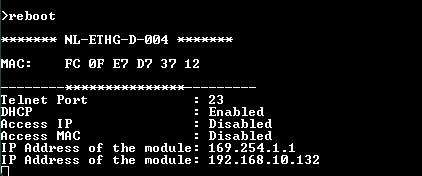
9. Login using the config user name and password as “admin” and send a “reboot” command.
10. The LED onboard near the USB connector will turn off and you can see the Config details on the terminal.
Please use this feature only for recovering the User name / Password. This action will reset the User name, Password, Device ID, and also other settings as well. After reset, the board can be accessed using the default User name and Password.
The factory default settings will be as below table.
| User name | admin |
| Password | admin |
| Config user name | admin |
| Config Password | admin |
| Device ID | 00000000 |
| IP Address | 169.254.1.1 |
| Telnet Authentication | ON |
| Telnet Port | 23 |
| DHCP Status | Enabled |
| The default settings provided below are only supported in firmware version A0M01.02 and later. |
|
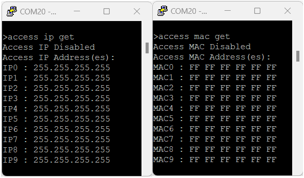
| Access IP | Disabled |
| IP0 to IP9 | 255.255.255.255 |
| Access MAC | Disabled |
| MAC0 to MAC9 | FF FF FF FF FF FF |
ADCs/DACs
The module has 4 Analog-Digital Converter(ADC) pins and 4 Digital-Analog Converter(DAC) pins that can be used for various custom applications. All ADC pins support voltage range upto ±10.24V. The ADC can acquire analog signal at the resolution of 16 bits per sample. It is recommended to use a series resistor with the ADC pins when interfacing with other circuits. All DAC pins support voltage range 0V to 10V(Unipolar). The DAC can produce output analog signal at the resolution of 12 bits per sample.
It is recommended to use a series resistor to protect the input from stray voltages and spikes.
The table below summarizes the Analog to Digital Converter input positions onboard.
| Analog Inputs | |
|---|---|
| AIN_0 | Analog Input 0 (Positive) |
| AIN_0_N | Analog Input 0 (Negative) |
| AIN_1 | Analog Input 1 (Positive) |
| AIN_1_N | Analog Input 1 (Negative) |
| AIN_2 | Analog Input 2 (Positive) |
| AIN_2_N | Analog Input 2 (Negative) |
| AIN_3 | Analog Input 3 (Positive) |
| AIN_3_N | Analog Input 3 (Negative) |
| A_5V0 | 5V |
| A_GND | GND |
The table below summarizes the Digital to Analog Converter input positions on the header P2.
| Digital Inputs | |
|---|---|
| VOUT _A | Digital Input 0 |
| DGND | Digital Ground |
| VOUT_B | Digital Input 1 |
| DGND | Digital Ground |
| VOUT_C | Digital Input 2 |
| DGND | Digital Ground |
| VOUT_D | Digital Input 3 |
| DGND | Digital Ground |
| VCC10V | 10V |
| DGND | GND |
Analog Inputs digital value calculation
Digital Value = [(Analog Input Value – Minimum Input Voltage)/ Total Input Range] X (Maximum Digital Value)
Note: Minimum Input Voltage and Total Input Range varies according to the range selected.
Max Digital Value is 65535.
Total Input Range = Maximum Input Voltage – Minimum Input Voltage.
More details available in the command set.
Configure 4 Channel Ethernet DAQ (4ADC-4DAC) Module
Connect a DC power supply and power up the device as mentioned in the DC Power Supply section above. A red LED (PWR) will glow which indicates active power. For configuration over USB connect the module to a PC using a USB A to B cable. Also connect the module to a PC or a Switch/Router as mentioned in the Ethernet Interface section above. Run any serial terminal program like TeraTerm, PuTTY, etc.
NB: By default, the module is configured with factory settings. To login to USB configuration settings, users need to send a reboot command from telnet or do a factory reset.
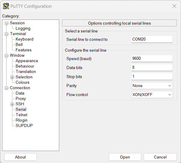
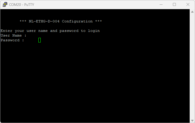
Select the module’s COM port and use the default settings similar to the below images and connect.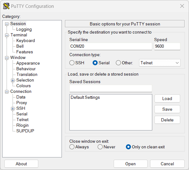
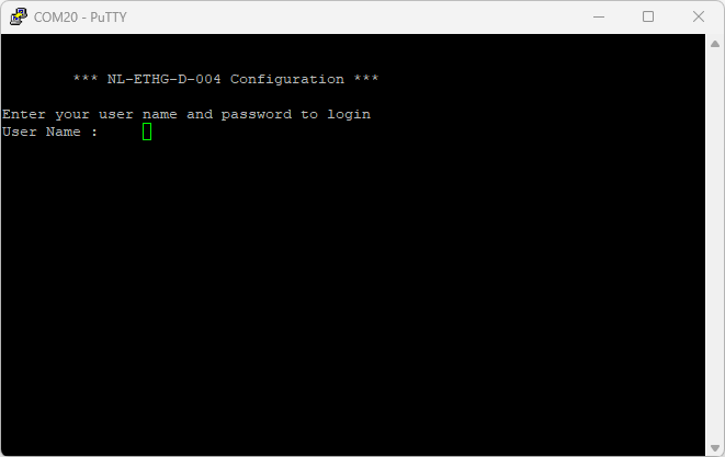
Users will be prompted to enter the User name and Password. The default User name and Password is ‘admin‘. You may change the User name and Password once logged in.
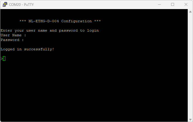
If the user name and password are correct, we will be able to see the login successfully message.
Configuration Command Set
| No. | Command | Example | Description |
| 1 | usr | usr set xxxxxxxx | where x can be any alphanumeric character. The username can be 1-8 characters long. |
| usr get | Read the current username of telnet. The default username is "admin". | ||
| 2 | pass | pass set xxxxxxxx | Sets the new password for telnet, where x can be any alphanumeric character. The password can be 1-8 characters long. |
| pass get | Read the current password of telnet. The default password is "admin". | ||
| 3 | config usr | config usr set xxxxxxxx | Sets the new username for configuration over USB, where x can be any alphanumeric character. The username can be 1-8 characters long. |
| config usr get | Read the current username of configuration over USB. The default username is "admin". | ||
| 4 | config pass | config pass set xxxxxxxx | Sets the new password for configuration over USB, where x can be any alphanumeric character. The password can be 1-8 characters long. |
| config pass get | Read the current password for configuration over USB. The default password is "admin". | ||
| 5 | telnet | telnet auth on/off | Enable and disable the telnet authentication. telnet auth on enabling the telnet authentication and telnet off disabling the telnet authentication. |
| telnet auth get | Read the status of telnet authentication. | ||
| telnet port set xx | Sets the telnet port, where xx can be in the range of 00 to 99. The default value of telnet port is 23. |
||
| 6 | dhcp | dhcp on/off | Enable or disable the DHCP of the module. |
| 7 | ip | ip set xxx.xxx.xxx.xxx | Sets the static IP to the module. Eg: ip set 192.168.5.48 |
| ip get | Read the status of DHCP or the static IP. If DHCP is enabled it will display the DHCP status and if it is disabled it will display the static IP. | ||
| 8 | mac id get | mac id get | Read the MAC id of the module. |
| 9 | reboot | reboot | Exit the configuration interface and enter to the application mode and start the telnet communication. |
| The below commands are supported only in firmware version A0M01.02 and later. | |||
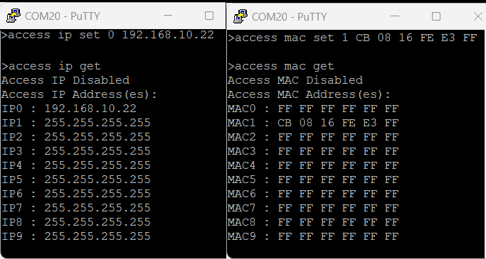
| 10 | access | access ip on/off | Enable or disabling the IP based access to the module, this command adds filtering. Once the command is enabled, the stored IP using the access ip set command will be able to access the module. By default access IP is disabled. |
| access ip set N xxx.xxx.xxx.xxx | Set the acceptable IP in the network and save the same. Where N is the number 0-9, maximum 10 IP we can store in the non-volatile memory. Eg: access ip set 0 192.168.0. 2 |
||
| access ip get | Read the stored IP in the memory. | ||
| access mac on/off | Enable or disabling the MAC-based access to the module, this command adds filtering. Once the command is enabled, the stored MAC using the access mac set command will be able to access the module. By default access MAC is disabled | ||
| access mac set N XX XX XX XX XX XX | Set the acceptable MAC in the network and save the same. Where N is the number 0-9, maximum 10 MAC we can store in the non-volatile memory. Eg: access mac set 0 D4 93 98 D2 4A 34 |
||
| access mac get | Reads the stored MAC in the memory. | ||
Configuration command Images
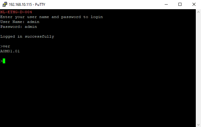
Example commands and results after executing the commands – version A0M01.01.
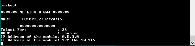
Example commands and results after executing the commands – version A0M01.02 & later.
Powering Up 4 Channel Ethernet DAQ (4ADC-4DAC) Module
Connect a DC power supply and power up the device as mentioned in DC Power Supply section above. A red LED (PWR) will glow which indicates active power. Connect the module to a Switch/Router as mentioned in the Ethernet Interface section above. Run Numato Lab Device Discoverer.jar, and click on Discover Devices. The window will display the IP address, Host Name, MAC Address, and Other information.
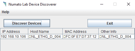
The MAC address of the Module is printed on a label on the board for your convenience. Use the IP address obtained in order to access the device.
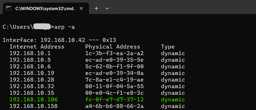
In version A0M01.02 the IP Address and MAC Address can be seen in the command prompt also, only after connecting the module through the web page. Open the command prompt and type the command ‘arp -a‘. This will display the available network interfaces and connected devices along with the MAC address and IP address of each device. Look for the IP address that corresponds to your device’s MAC address.
Accessing the Module
The module can be controlled by using all of the three interfaces below.
- Through HTML/Web Page served from the device.
- Through a Serial Terminal Emulator that supports TELNET (Eg: Hyper terminal, Teraterm, PUTTY…)
- Through HTTP commands
Accessing the module using web interface
The easiest method for controlling the module is through web page served from the device. To open the administration web page, type in the IP address in to the address bar of any web browser and press enter.
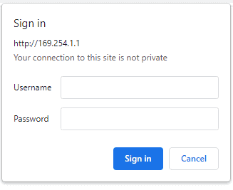
You will prompted to enter User name and Password. The default User name and Password is ‘admin’. You may change the User name and Password once logged in.
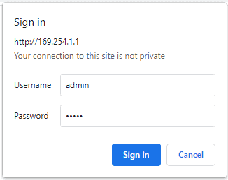
Enter the default User name and Password then click OK.
You will be presented with the device home page that shows the status of ADCs and DACs
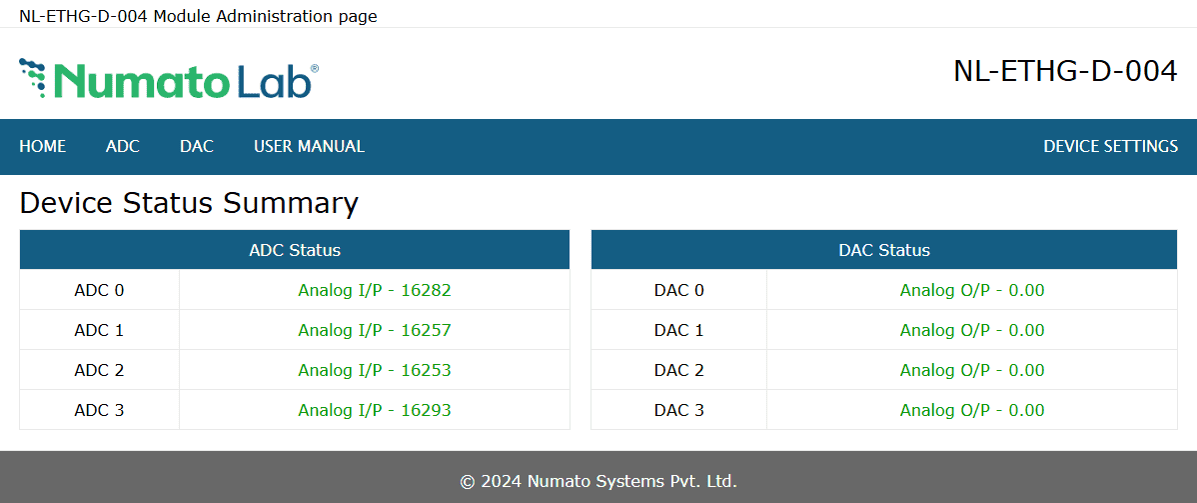
The USER MANUAL link on the menu bar is only present in version A0M01.02 and later.
ADC and DAC
This board has 4 analog inputs and 4 analog outputs. Click on the ADC link on the menu bar to access ADC configuration page. Click on the DAC link on the menu bar to access DAC configuration page.
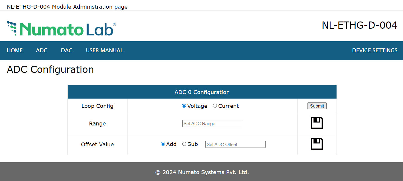
Analog Input (ADC)
The value of the analog inputs is displayed in this section.
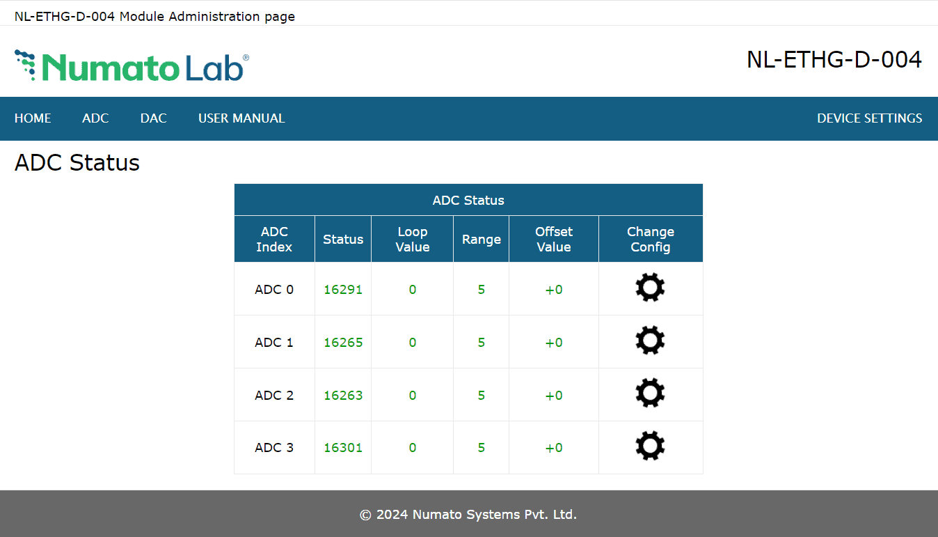
The ADC input range is -10.24V to +10.24V, the default range is 5(0 to +10.24V). The ADC can acquire analog signal at the resolution of 16 bits per sample. It is recommended to use a series resistor with the ADC pins when interfacing with other circuits.
Loop config can be selected and the range, offset value recommended in the command set can be set to the ADCs.
In version A0M01.02 and later to configure an ADC’s loop, range and offset, click on the corresponding ADC’s Change Config button. Select voltage or current radio and click the Submit button. Enter the ADC range in the input box and click the Save icon. Select Add or Sub radio, entyer offset value and click the Save icon.
The USER MANUAL link on the menu bar is only present in version A0M01.02 and later.
Analog Output (DAC)
Analog Outputs are displayed on the webpage.
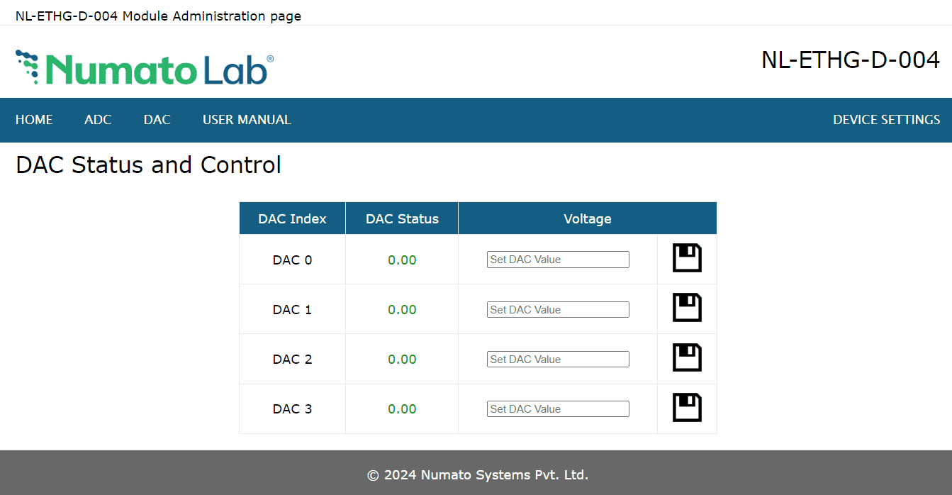
The DAC input range is 0 to +10V. The DAC can acquire input signal at the resolution of 12 bits per sample.
The USER MANUAL link on the menu bar is only present in version A0M01.02 and later.
Device Settings
Device Settings page displays the current firmware version, Device ID, Account Settings and Basic Network Settings. A logged-in user can change and save the Device ID, User name, Password and network settings.
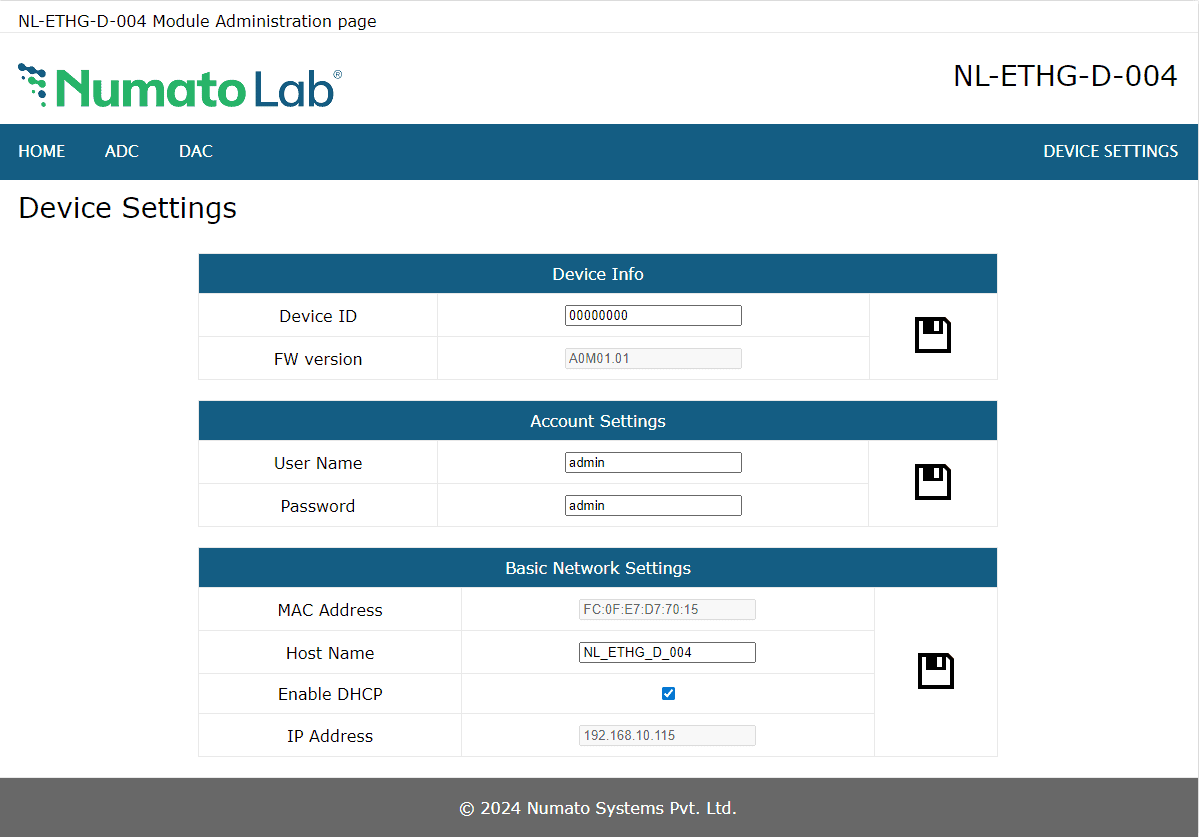
In the above image, the firmware version is displayed as A0M01.01, default device ID 00000000, default User name and Password as ‘admin’. The user can change and save the Device ID, User name and Password as explained in command set or changing the appropriate field on this page and clicking on the save button on the right side. The User name and Password can be reset to factory defaults via Factory Reset explained elsewhere in this document. The Basic Network Settings Shows the Device MAC address, Host Name, and IP Address. The default hostname and IP Address can also be changed according to the user’s wish. After saving changes the board will reboot with the new network settings.
The USER MANUAL link on the menu bar is only present in version A0M01.02 and later.
Controlling the module through TELNET interface
The simple set of ASCII based human readable command sets supported by this module makes controlling relays easy via TELNET protocol very easy. The following sections give examples of how to use the module with PuTTY and TeraTerm.
To use this module with PuTTY, please follow the steps below.
- Connect the module to the LAN.
- Open PuTTY and enter the IP address corresponding to the module, leaving the port number as 23.
- Click Open.
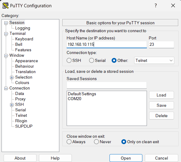
- If everything goes well, you should be presented with a screen as below.
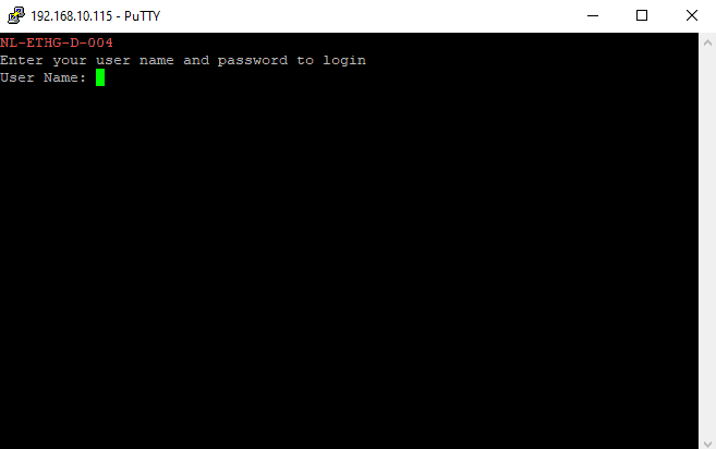
- Type in the TELNET User name and Password when asked and press enter key.
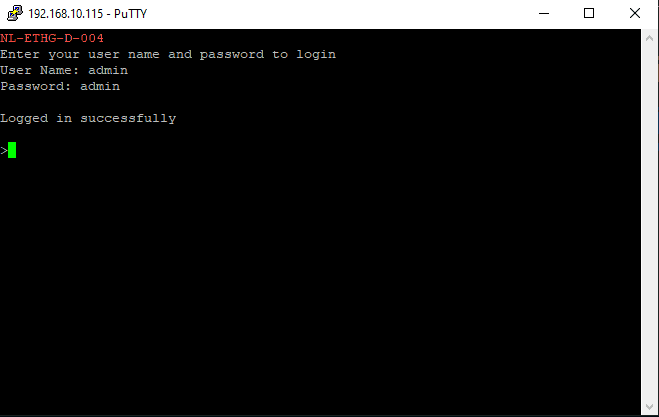
- Commands listed in the table in section “Sending Commands” can be entered here now. For example, here is the response for “ver” command.
Using this module with TeraTerm is just as easy. Please follow the steps below.
TeraTerm is an open source software. A free copy can be downloaded from http://en.sourceforge.jp/projects/ttssh2/releases/
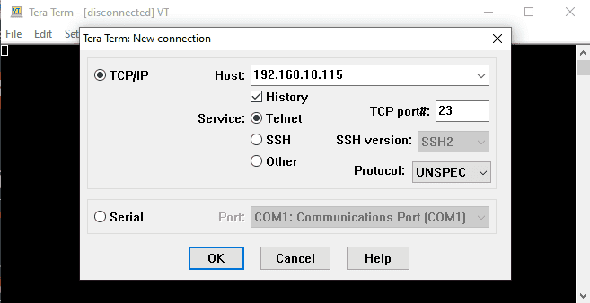
- Run TeraTerm and type in the IP address corresponding to the module in the “New connection” dialog and click OK.
- Then select the terminal setup from the setup button and make sure the settings are as shown below, and press OK.
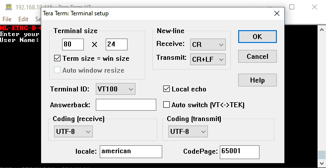
- Type the User name and Password when asked.
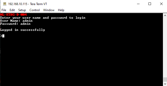
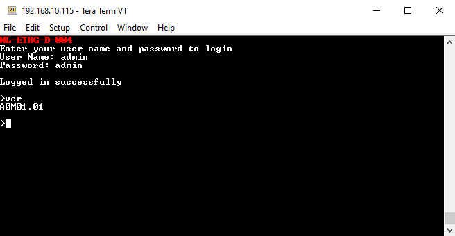
- Press ENTER key and the command prompt should appear. Commands listed in the table in section “Sending Commands” can be entered here now. For example, here is the response for “ver” command.
Sending Commands
One of the most powerful features of this module is the simple easy to use command set it supports. This command set allows for a very simple interface to access the features of the module through the TELNET protocol. The following sections give details of the command set and how to use the command set.
The Commands Set
This product supports a very simple command set that is designed to be less cryptic and easy to use manually (using serial terminal emulation programs that support TELNET) or through a program written in many supported languages.
List of currently supported commands.
| No. | Command | Parameters | Usage | Description |
|---|---|---|---|---|
| 1 | ver | none | ver | Returns firmware version |
| 2 | id | get | id get | Reads Module ID |
| set xxxxxxxx | id set 12345678 | Assign ID to the module | ||
| 3 | usr | get set xxxxxxxx | usr get usr set admin | Read user name of the module Set user name of the module |
| 4 | pass | get set xxxxxxxx | pass get pass set admin | Read password of the module Set password of the module |
| 5 | adc | range set xxx z | adc range set 003 2 | ADC voltage range selection |
| range get xxx | adc range get 001 | Returns ADC voltage range value | ||
| read xxx | adc read 003 | Returns ADC value | ||
| config set x | adc config set 1 | ADC configuration selection | ||
| config get | adc config get | Retuns ADC configuration value. | ||
| offset set xxx z XXX | adc offset set 002 0 0100 | Setting ADC offset state & value | ||
| offset get xxx | adc offset get 001 | Returns ADC offset state and value | ||
| 6 | dac | set xxx XXXX | dac set 002 4.56 | Setting DAC output voltage |
| read xxx | dac read 001 | Reads DAC output value | ||
| 7 | reboot | None | reboot | Exit the application mode and enter to the configuration interface and start the configuration via USB. |
| The command shown below is supported only in firmware version A0M01.02 and later | ||||
| 8 | info | None | info | Displays device information like Name, IP address, MAC ID, etc.. |
The table below has more detailed information about available commands.
| No. | Command | Usage | Description |
|---|---|---|---|
| 1 | ver | ver | Returns firmware version. |
| 2 | id | id get | Reads the module ID. |
| id set xxxxxxxx | Assign an 8-digit ID to the module, where ‘x’ can be any alphanumeric character. | ||
| 3 | usr | usr get | Reads the user name of the module. |
| usr set xxxxxxxx | Set new user name to the module. “x” stands for alphanumeric characters including symbols. The user name can be 1 – 8 characters length. |
||
| 4 | pass | pass get | Reads the password of the module. |
| pass set xxxxxxxx | Set new password to the module. “x” stands for alphanumeric characters including symbols. The password can be 1 – 8 characters length. |
||
| 5 | adc | adc range set xxx z | ADC “xxx”s voltage range is set to “z”. The default voltage range is 5. Where, xxx - adc number, 000 to 003. z - voltage range select option, 0 to 8. z values & voltage ranges ---------------------------------- 0 - ±10.24V 1 - ±5.12V 2 - ±2.56V 3 - ±1.28V 4 - ±0.64V 5 - 0 to 10.24V 6 - 0 to 5.12V 7 - 0 to 2.56V 8 - 0 to 1.28V adc range set 001 4 – The ADC 1 is set to voltage range 4. |
| adc range get xxx | Reads the range status of the ADC Number ‘xxx’. adc range get 002 – Returns the range of the ADC number 2. Where, xxx = 000 to 003. |
||
| adc read xxx | Read the input status present at ADC ‘xxx’. adc read 003 – Read input status of ADC3 and print. xxx can be 000 – 003 |
||
| adc config set x | Set ADC config status to ‘x’. The default adc config state is 0 i.e voltage loop. Each bit position of x corresponds to ADC0 to 3. A 0 in bit position indicates that the particular adc pin is in voltage loop and 1 it indicates the particular adc pin is in current loop. adc config set 1 – the value 1 (0001) changes ADC 0 config state to current loop 4 - 20mA. x can be in range - 0 to F. |
||
| adc config get | Returns the ADC configuration value. The output returned will be based on the loop ADC is configured. The value 0 in bit position indicates that the ADC is configured in ‘Voltage’ loop and value 1 indicates ‘Current’ loop. |
||
| adc offset set xxx z XXXX | Setting adc offset value ‘XXXX’. The default state will be z-0, XXXX-0000. adc offset set 002 0 100 – Adding value 100 to ADC 2. Where, xxx – Adc number, 000 – 003. z – Offset add/subtract, 0 – Add; 1 – Subtract. XXXX – Offset Value, 0000 – 9999. |
||
| adc offset get xxx | Returns the offset value set to the ADC number ‘xxx’. The state +/-(Addition/Subtraction) of offset is also returned. adc offset get 003 – returns +/- and value of offset. Where, xxx = 000 to 003. |
||
| 6 | dac | dac set xxx XXXX | Setting the DAC voltage input value ‘XXXX’ to DAC ‘xxx’. dac set 001 2.33 – Setting the DAC 1 output to 2.33V. Where, xxx - DAC number, 000 – 003. XXXX – DAC voltage value 0 – 10V (floating). |
| dac read xxx | Read DAC ‘xxx’ status. dac read 002 – Reads DAC 2 status and prints the output voltage value. Where, xxx = 000 to 003. |
||
| 7 | reboot | reboot | Exit the application mode and enter to the configuration interface and start the configuration via USB. |
| The command shown below is supported only in firmware version A0M01.02 and later | |||
| 8 | info | info | Displays device information like Name, IP address, MAC ID, etc.. |
NOTE!
- For the command adc offset set, set the offset value based on the ADC value, while subtracting the offset value must be less than the ADC read value.
Egs :- adc offset set 000 1 10, if the value of ADC 0 is 100. Subtracting 10 from 100, the ADC 0 value becomes 90. - The Maximum ADC value is 65535, No offset value should be added. The value of offset added should not make ADC value exceed 65535.
Egs :- adc offset set 000 0 20, if the value of ADC 0 is 65500, Adding 20 to 65500, the ADC 0 value becomes 65520.
Controlling through HTTP commands
This module supports HTTP commands.
Refer to the ‘HTTP Command Set‘ knowledge base to know more.
Below are some of the images related to controlling this modules through HTTP commands.
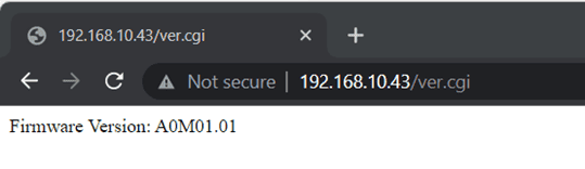
fig 1: Displays firmware version
fig 2: Displays device ID
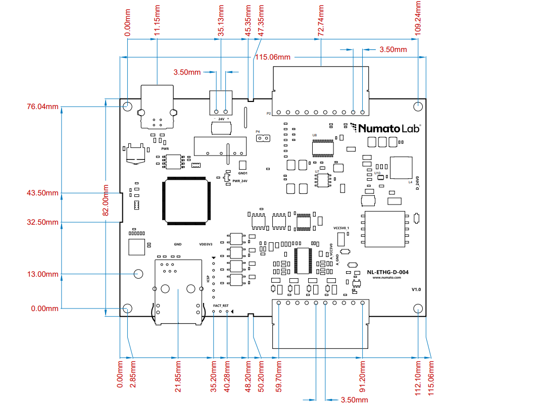
Mechanical Dimensions