Introduction
Mimas ECP5 Mini FPGA Development board is a simple FPGA board having Lattice ECP5 FPGA (LFE5U-45F-7BG256I package) with FTDI’s FT2232H Dual-Channel USB device. The Lattice ECP5 FPGA family is renowned for breaking the rules of power, size, and cost in your connectivity and acceleration applications. The USB 2.0 host interface based on the popular FT2232H offers high bandwidth data transfer and board programming without the need for any external programming adapters.
Board Features
- Device: Lattice ECP5 FPGA (LFE5U-45F-7BG256I)
- DDR3: 2Gb DDR3 (MT41J128M16JT-125 or equivalent)
- Built-in programming interface. No expensive JTAG adapters are needed for programming the board
- Onboard 128Mb flash memory for FPGA configuration storage and custom user data storage
- High-speed USB 2.0 interface for Onboard flash programming.
- 4 LEDs, 1 RGB LED, and 4 Push Buttons for user-defined purposes
- FPGA configuration via JTAG and USB
- Maximum IOs for user-defined purposes
- FPGA – 70 IOs (35 professionally length matched Differential Pairs) and two 2×6 Expansion Headers
Applications
- Product Prototype Development
- Accelerated computing integration
- Development and testing of custom-embedded processors
- Communication devices development
- Educational tool for Schools and Universities
How to use Mimas ECP5 mini FPGA development Board
The following section describe in detail how to use this module
Hardware Accessories Required
For easy and fast installation, you may need the following items along with the Mimas ECP5 Mini module.
- USB-C type cable
- DC Power Supply
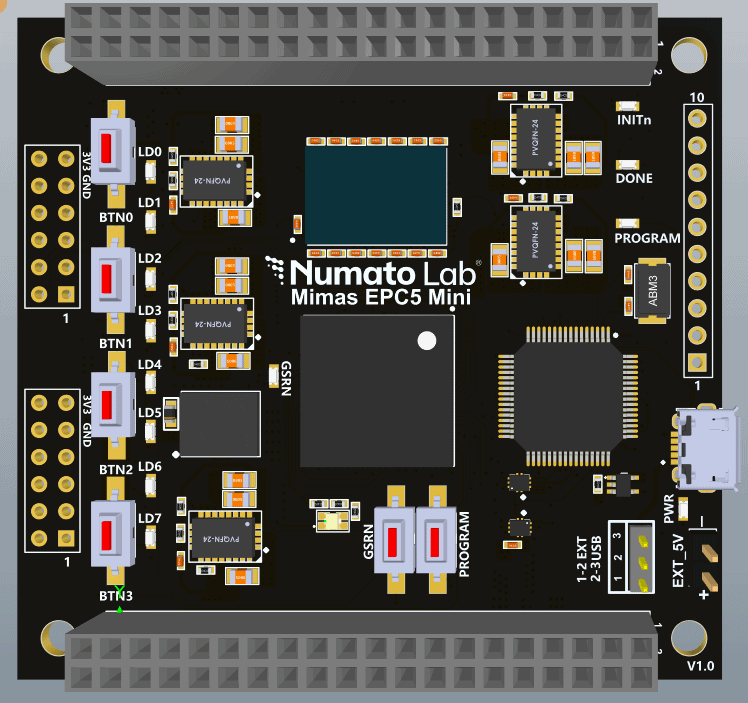
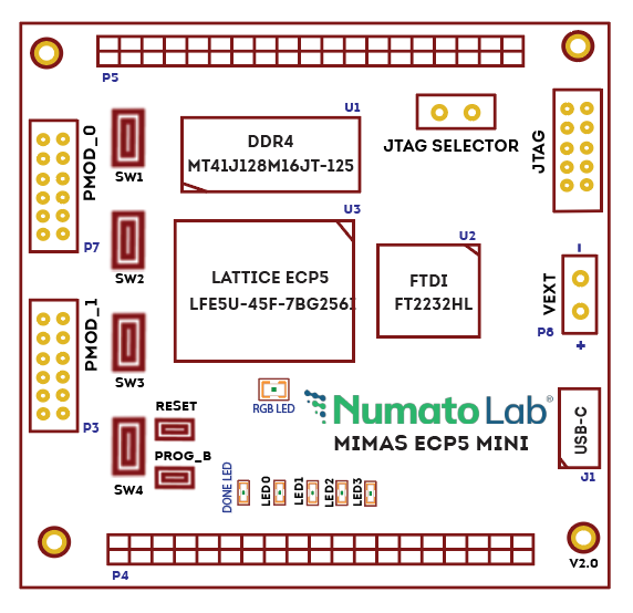
Connection Diagram
The following connection diagram should be used for reference only. The schematics are available at the end of this document for detailed information.
USB Interface
The onboard full-speed USB controller helps a PC/Linux/Mac computer to communicate with this module.
By default, the module is powered by USB, so make sure not to overcrowd unpowered USB hubs.
Note: Mimas ECP5 Mini ships with FT2232H Channel A dedicated to JTAG Programming.
External Power Supply
The board can be configured to use an External power supply by connecting it to the External +5V supply. Please refer to the marking on the board for more details (the picture on the right shows the External +5V supply connector).

PROG_B and Reset Buttons
Mimas ECP5 Mini features a Push-button PROG_B normally used as a “PROG_B” signal for configuration reset. Push-button PROG_B is connected to FPGA pin R9. For enabling manual configuration reset, push-button PROG_B is connected to GND. The user can reconfigure the FPGA manually, by pressing this push-button PROG_B.
“PROG_B” controls the configuration logic. When the PROG_B pin is de-asserted, it resets the FPGA and initializes the new configuration.
Mimas ECP5 Mini features a Push-button RESET normally meant to be used as a “Reset” signal for designs running on FPGA. Push-button RESET is connected to FPGA pin A4. Push-button RESET is active-high. This push button can also be used for any other input and is not limited to being used as a Reset signal.
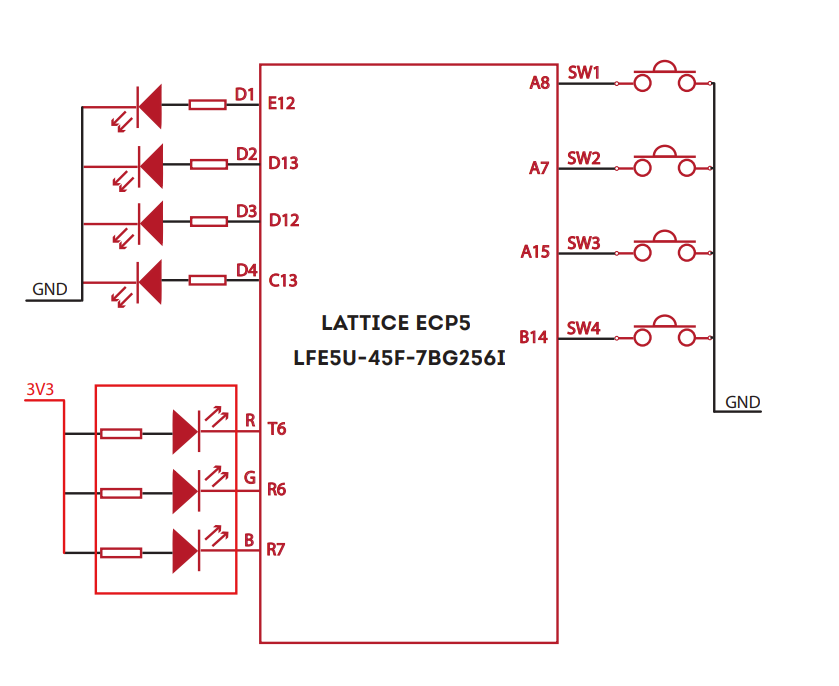
LEDs, RGB LED and Push Button
Mimas ECP5 Mini Development Board has four push-button switches, one RGB LED, and four LEDs for human interaction. All switches are directly connected to Lattice ECP5 FPGA and can be used in your design with minimal effort.
GPIOs
This device is equipped with a maximum of 70 user IO pins that can be used for various custom applications. All user IOs are length matched and can be used as differential pairs.
Header P4
| Pin No. On the Header | GPIO Pin Name | ECP5 (7BG256I) Pin No. | Pin No. On the Header | GPIO Pin Name | ECP5 (7BG256I) Pin No. |
|---|---|---|---|---|---|
| 2 | GND | 1 | VCCIO | ||
| 4 | GPIO_1_P | B16 | 3 | GPIO_1_N | B15 |
| 6 | GPIO_2_P | C16 | 5 | GPIO_2_N | C15 |
| 8 | GPIO_3_P | D16 | 7 | GPIO_3_N | E15 |
| 10 | GPIO_4_P | G12 | 9 | GPIO_4_N | G13 |
| 12 | GPIO_5_P | F16 | 11 | GPIO_5_N | G15 |
| 14 | GPIO_6_P | G16 | 13 | GPIO_6_N | H15 |
| 16 | GPIO_7_P | H12 | 15 | GPIO_7_N | H13 |
| 18 | GPIO_8_P | K13 | 17 | GPIO_8_N | K12 |
| 20 | GPIO_9_P | J16 | 19 | GPIO_9_N | J15 |
| 22 | GPIO_10_P | J14 | 21 | GPIO_10_N | K14 |
| 24 | GPIO_11_P | K16 | 23 | GPIO_11_N | K15 |
| 26 | GPIO_12_P | L16 | 25 | GPIO_12_N | L15 |
| 28 | GPIO_13_P | N16 | 27 | GPIO_13_N | P15 |
| 30 | GPIO_14_P | P16 | 29 | GPIO_14_N | R16 |
| 32 | GPIO_15_P | N13 | 31 | GPIO_15_N | P14 |
| 34 | GPIO_16_P | P13 | 33 | GPIO_16_N | R14 |
| 36 | GPIO_18 | R12 | 35 | GPIO_17 | T13 |
| 38 | GPIO_20 | N11 | 37 | GPIO_19 | M11 |
| 40 | GND | 39 | VCCIO |
Header P5
| Pin No. On the Header | GPIO Pin Name | ECP5 (7BG256I) Pin No. | Pin No. On the Header | GPIO Pin Name | ECP5 (7BG256I) Pin No. |
|---|---|---|---|---|---|
| 2 | VCCIO | GND | |||
| 4 | GPIO_22 | E16 | 3 | GPIO_21 | C14 |
| 6 | GPIO_24 | F15 | 5 | GPIO_23 | D14 |
| 8 | GPIO_26 | E14 | 7 | GPIO_25 | F14 |
| 10 | GPIO_28 | F12 | 9 | GPIO_27 | F13 |
| 12 | GPIO_30 | C9 | 11 | GPIO_29 | B9 |
| 14 | GPIO_32 | E9 | 13 | GPIO_31 | D9 |
| 16 | GPIO_34 | C8 | 15 | GPIO_33 | B8 |
| 18 | GPIO_36 | E8 | 17 | GPIO_35 | D8 |
| 20 | GPIO_38 | J13 | 19 | GPIO_37 | J12 |
| 22 | GND | 21 | GND | ||
| 24 | GPIO_40 | L13 | 23 | GPIO_39 | L12 |
| 26 | GPIO_42 | M12 | 25 | GPIO_41 | N12 |
| 28 | GPIO_44 | P12 | 27 | GPIO_43 | P11 |
| 30 | GPIO_46 | M14 | 29 | GPIO_45 | M13 |
| 32 | GPIO_48 | R13 | 31 | GPIO_47 | N14 |
| 34 | GPIO_50 | L14 | 33 | GPIO_49 | M15 |
| 36 | GPIO_52 | T15 | 35 | GPIO_51 | T14 |
| 38 | GPIO_54 | M16 | 37 | GPIO_53 | R15 |
| 40 | VCCIO | 39 | GND |
Header P10 (2x6 Expansion Header)
| Pin No. On the Header | GPIO 2x6 CONNECTOR Pin Name | ECP5 (7BG256I) Pin No. | Pin No. On the Header | GPIO 2x6 CONNECTOR Pin Name | ECP5 (7BG256I) Pin No. |
|---|---|---|---|---|---|
| 6 | VCC | 12 | VCC | ||
| 5 | GND | 11 | GND | ||
| 4 | CONN1_D3 | C10 | 10 | CONN1_D7 | A14 |
| 3 | CONN1_D2 | B10 | 9 | CONN1_D6 | A13 |
| 2 | CONN1_D1 | E10 | 8 | CONN1_D5 | A12 |
| 1 | CONN1_D0 | D10 | 7 | CONN1_D4 | A11 |
Header P7 (2x6 Expansion Header)
| Pin No. On the Header | GPIO 2x6 CONNECTOR Pin Name | ECP5 (7BG256I) Pin No. | Pin No. On the Header | GPIO 2x6 CONNECTOR Pin Name | GPIO 2x6 CONNECTOR Pin Name |
|---|---|---|---|---|---|
| 6 | VCC | 12 | VCC | ||
| 5 | GND | 11 | GND | ||
| 4 | CONN0_D3 | A10 | 10 | CONN0_D7 | G14 |
| 3 | CONN0_D2 | A9 | 9 | CONN0_D6 | H14 |
| 2 | CONN0_D1 | E11 | 8 | CONN0_D5 | C12 |
| 1 | CONN0_D0 | D11 | 7 | CONN0_D4 | B12 |
FT2232H – ECP5(7BG256I) FPGA Connection Detail
| FTDI Pin No. | Pin Function (245 FIFO) | ECP5 (7BG256I) Pin No. |
|---|---|---|
| 38 | FTDI_D0 | E6 |
| 39 | FTDI_D1 | D6 |
| 40 | FTDI_D2 | A5 |
| 41 | FTDI_D3 | A6 |
| 43 | FTDI_D4 | C5 |
| 44 | FTDI_D5 | B5 |
| 45 | FTDI_D6 | E5 |
| 46 | FTDI_D7 | D5 |
| 48 | FTDI_RXE_N | C4 |
| 52 | FTDI_TXE_N | B4 |
| 53 | FTDI_RD_N | E4 |
| 54 | FTDI_WR_N | D4 |
| 55 | FTDI_SIWUA_N | A3 |
Driver Installation
Windows
This product requires a D2XX driver to be installed for proper functioning when used with Windows. The driver can be downloaded from D2XX drivers. When the driver installation is complete, the module should appear in FT_Prog Tool as Mimas ECP5 Mini FPGA Development Board.
Linux
The Linux ships with the drivers required for Mimas ECP5 Mini.
Programming Mimas ECP5 Mini
Step 1:
Before Programming make sure to populate Jumper P1. Power up Mimas ECP5 Mini Development board by connecting the USB C cable.
Step 2:
Open “Diamond Programmer.
![]()
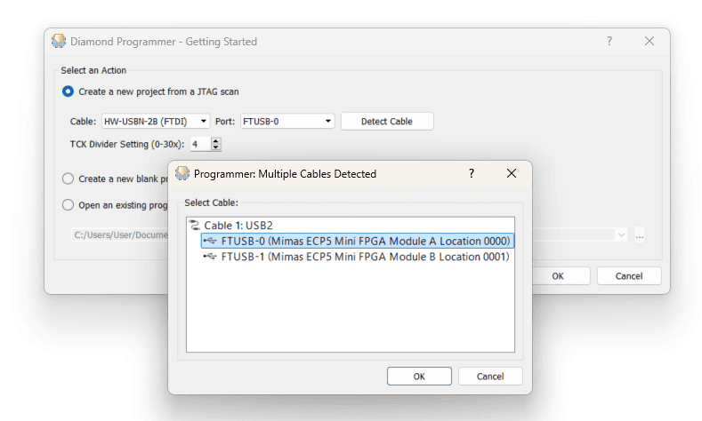
Step 3:
Click on “Detect Cable” and select the correct port. Click “OK”
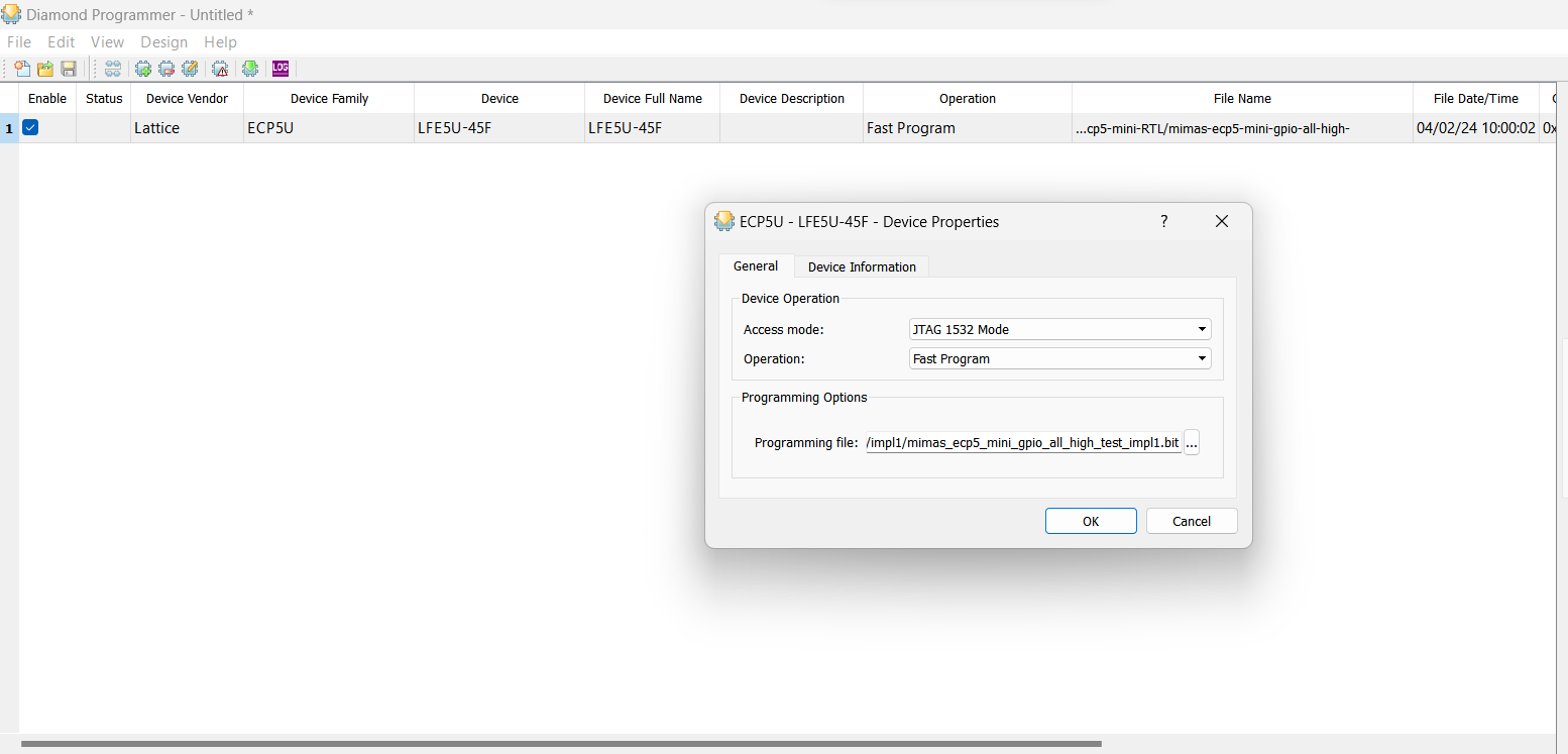
Step 4:
Select the Operation as “Fast Program” and browse the Corresponding Bitstream file in the File Name box.
Step 5:
For programming SPI Flash Select the “Operation” as given below.
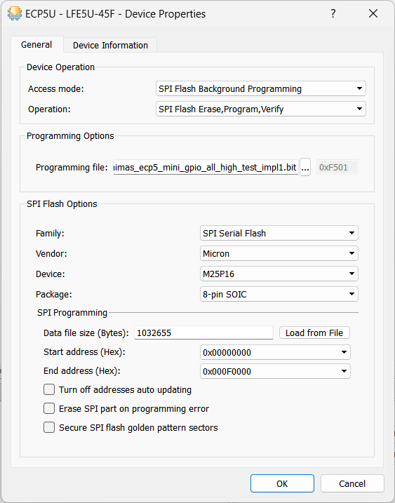
Step 6:
Finally, click on “Program” (![]() ).
).
Note: SPI Flash Background Programming is only possible when the ECP5-5G device is erased or when the active design has the MASTER_SPI_PORT mode enabled. Therefore, when performing SPI Flash Background Programming, ensure the PROGB button is held down until programming is completed.
Technical Specifications
| Parameter * | Value | Unit |
|---|---|---|
| Basic Specifications | ||
| Number of GPIOs | 70 | |
| On-board oscillator frequency (ASEM1-100.000MHZ-LC-T) | 100 | MHz |
| DDR3 SDRAM (MT41J128M16JT-125 or equivalent) | 2 | Gb |
| Quad SPI Flash Memory (M25P16) | 128 | Mb |
| Power supply voltage (USB or External) | 5 | V |
| Number of LEDs | 4 | |
| Number of Push Buttons | 4 | |
| FPGA Specifications | ||
| Internal supply voltage relative to GND | -0.5 to 1.1 | V |
| Auxiliary supply voltage relative to GND | -0.5 to 2.0 | V |
| Output drivers supply voltage relative to GND | -0.5 to 3.6 | V |
| Temperature range | 0 to 70 | °C |
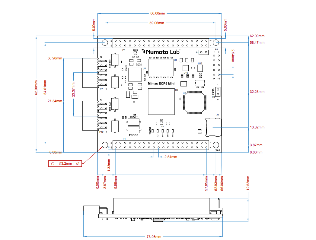
Physical Dimensions