1.Introduction
64 Channel USB MOSFET Switch is a highly adaptable solution for remotely managing electrical and electronic devices via a PC through a USB connection. The foremost objectives in its design are user-friendliness and broad compatibility with operating systems. Featuring built-in USB-to-serial conversion, the module can be utilized effortlessly without necessitating specialized USB expertise. This simplicity allows the use of readily available Terminal Emulation software like HyperTerminal and PuTTY, facilitating control through a straightforward array of human-readable commands. Furthermore, for advanced users, this module can be seamlessly integrated into programs crafted in diverse programming languages.
Features:
- 64 Channel MOSFET Outputs
- LEDs for each output
- USB interface with CDC support. As easy as using a serial port, no USB knowledge is required
- Can be powered from USB or external power supply
- Can be controlled by using standard serial console applications or custom applications
Some of the possible uses of this module include:
- Industrial Automation
- Process Control Systems
- Motor Control
- Test and Measurement Equipment
- Lighting Control
This product is compatible with the following operating systems:
- Windows XP and later versions (Windows 7, 8/8.1, 10 and future versions)
- Windows 7 Embedded and later
- Linux
- Mac OS X
- Android
- Or any other operating system that supports USB CDC devices.
And these are some of the languages that can be used for programming:
- C/C++
- Visual Basic (VB6, VB2008, VB2010 express and other editions)
- Visual Basic for Applications (Microsoft Office VBA)
- Perl
- Python
- JAVA
- Android
- Javascript (Node.js)
- And many more…
This module has 64 onboard MOSFET Switches each available on easy-to-plug headers and associated drivers capable of controlling a large number of devices. The module communicates with the host PC over a full-speed USB link. When connected to a PC, the module will appear as a serial port in Windows Device Manager (or a serial tty device in Linux and Mac).
2.How to Use 64 Channel USB MOSFET Switch
Using this product is very easy, thanks to the human readable and easy to use command set and the USB CDC interface that allows the device to be used with most readily available serial terminal software such as Tera Term or HyperTerminal. Some of the software are mentioned below.
- Windows
- Tera Term
- Linux
- GNU Screen
- PuTTY
- Mac OS X
- Screen Command
- CoolTerm
- goSerial
Using this product involves the following simple steps.
- Connect the device to a USB port on the host system
- Install driver (Only needed for Windows)
- Open the COM port corresponding to the device using a Serial Terminal software
- Enter commands (Very similar to entering commands at DOS prompt or Bash prompt)
- Optionally write a script or application to automate your task (More info on custom programming/scripting is available in this document.
All aspects of the above steps are covered in the following sections including step by step demonstration.
2.1.Components/Tools Required
Along with the module, you may need the items in the list below for easy and fast installation.
1. USB A to USB B cable.
2. Small screwdriver.
2.2.USB Interface
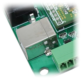 The onboard full-speed USB controller helps a PC/Linux/computer to communicate and control this module seamlessly. Use a USB A to USB B cable to connect with a PC. Please visit Cables|Numato Lab to buy cables and accessories for this product. By default, the logic section of the module is powered from USB so make sure not to overcrowd unpowered USB hubs (the picture on the right shows USB B connector).
2.3.DC Power Supply
This module uses a +5V power supply to function properly. By default, the board is configured to use a +5V supply from USB. In most cases, USB ports are capable of providing enough current for the module. So external power is not required unless the USB port is unable to supply enough current. If needed, connect a +5V power supply to the ‘EXT_5V’ terminal on the module. Make sure to connect the power supply to the correct polarity. It has an onboard DC Barrel Jack Adapter, so we can directly connect the power supply which has a Barrel Jack connector.
2.4.Connection Details
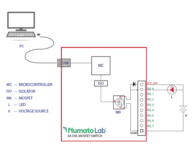
The picture above shows the basic connection diagram. Use a USB A to B cable to connect with a PC. It is important to make sure that the wires used to connect loads are sufficiently rated to handle the expected load current. Exercise caution while working with high voltages. Short circuits can cause damage to the module and the PC.
3.Driver Installation
3.1.Installing Numato Lab CDC Driver - Windows Desktop and Server Editions
To install the driver, attach a USB cable to the PC, and when asked by the Windows device installation wizard, point to the folder where the Numato Lab USB CDC Driver files are present. When driver installation is complete, the module should appear in Windows Device Manager as a serial port. The picture below shows a 64-channel USB MOSFET Switch(NL-USBG-M-064) visible in Windows Device Manager. For other devices, the name will be different but how the device is displayed and used is the same.
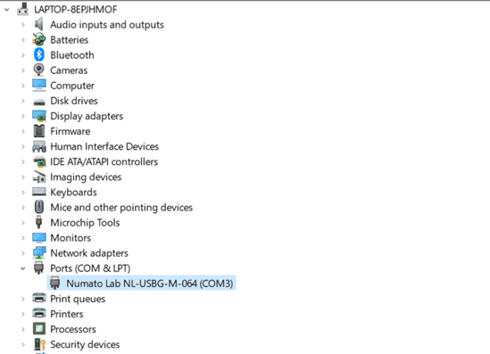
Note down the name of the serial port (COM1, COM2 etc..). This information is required to control the module from the PC.
You may notice that the driver package does not come with a .sys or .exe file as most driver packages do and is expected to be that way. The driver binary necessary in this case is shipped with all copies of windows Desktop/Server editions and gets installed automatically while Windows is installed for the first time. The .inf and .cat files present in the driver package downloaded from http://numato.com merely associate this pre-existing driver with the attached Numato Lab device.
The following video demonstrates how to install the driver on Windows 10.
3.2.Installing on Windows Embedded Editions
Windows Embedded editions do not install the infrastructure necessary for USB CDC by default in favor of a smaller footprint. This will cause the driver install to fail unless the necessary files are manually installed prior to installing the driver. Please follow the steps below to install the prerequisites and driver correctly. These steps are tested on Windows 7 Embedded Edition.
- Locate winemb-inf-mdmcpq.cab on Win 7 Embedded DVD/ISO image
- Copy winemb-inf-mdmcpq.cab to a folder Ex: C:Temp
- Run command DISM.exe /online /Add-Package /PackagePath:C:Temp
- Wait for Windows to restart (Restart machine manually if DISM does not restart the machine automatically)
- After reboot is complete, plug the device to a USB port and install driver normally (Driver is available for download at the product page)
3.3.Installing on Mac OSX
Mac OSX is usually shipped with USB CDC driver pre-installed. When connected to a Mac computer, this product should appear as a serial port under /dev directory. Usually the name of the device will be tty.usbserialportx or similar. The name may be different depending on the Mac OSX version you have. The image below shows the result of ls /dev/*usb* command on a Mac OSX Yosemite system with a USB GPIO/Relay device attached.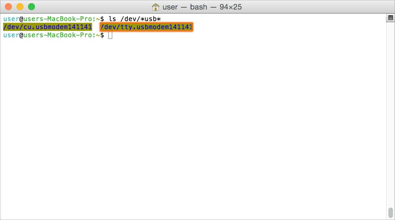
In this particular case, the device shows up as tty.usbmodem141141 (highlighted on orange color) but it could be any name starting tty.usbmodem or even a completely different name depending on the exact version of operating system and other connected devices. Once the device is visible under /dev directory, it can be treated just like any other serial device. Commands can be sent to the device using any mechanism that is valid for regular serial ports such as screen command or Serial Terminal Emulation applications. If there are more than one devices connected to the same host computer, each device will be displayed as separate serial devices with unique names. These separate serial devices can be used to control individual devices attached.
3.4.Installing CDC Devices On Android
Most Android versions has built in driver that supports external USB Devices. Due to the presence of built-in driver any external USB device including Numato Lab’s USB GPIO/Relay products connected to Android based gadget will be enumerated by Android OS. Such enumerated devices can be listed/viewed by using apps such as USB Device Info. The image below shows info about a Numato Lab USB device printed by USB Device Info app.
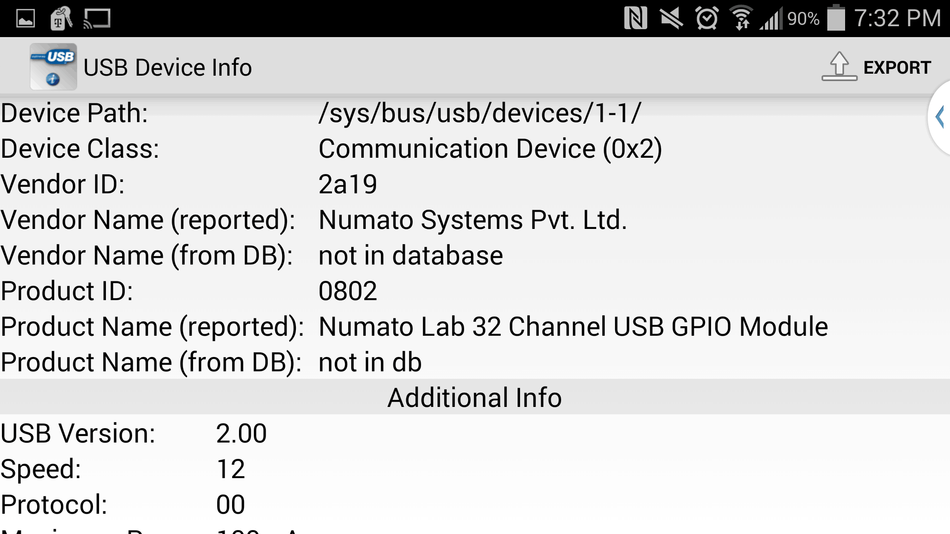
Devices detected by Android can be controlled by using any off the shelf Serial Terminal App such as USB Serial Terminal Lite.
4.Sending Commands
One of the most powerful features of this module is the simple easy to use command set it supports. This command set hides the complex USB protocol and gives a very simple interface to access the features of the module. The following sections give details of the command set and how to use the command set.
4.1.The Commands Set
This product supports a very simple command set that is designed to be less cryptic and easy to use manually (using serial terminal emulation programs) or through a program written in many supported languages.
List of currently supported commands.
| No. | Command | Parameters | Example | Description |
|---|---|---|---|---|
| 1 | ver | none | ver | Returns firmware version. |
| 2 | id | get/set xxxxxxxx | id get, id set 12345678 | Reads/Writes ID of the module |
| 3 | gpio | set/clear/status/readall/ writeall/poweron/iomask, gpio number | gpio set 000 | Control General Purpose Input/Output |
| 4 | info | none | info | Display information about the module including GPIO power-on status. |
The table below has more detailed information about available commands.
| No. | Command | Example | Description |
|---|---|---|---|
| 1 | ver | ver | Returns current firmware version. |
| 2 | id | id get | Reads the module ID. |
| id set xxxxxxxx | To assign a new ID to the module. “x” stands for alphanumeric characters including symbols. The new ID must be exactly 8 characters in length. |
||
| 3 | gpio | gpio set xxx | Sets the output status to high. “xxx” is the output number. The GPIO number can be in the range 000 – 063 Please see the examples below – gpio set 000 – Sets MOSFET output 0 to high state. gpio set 009 – Sets MOSFET output 9 to high state |
| gpio clear xxx | Sets the output status to low. “xxx” is the output number. The GPIO number can be in the range 000 – 063 Please see the examples below – gpio clear 000 – Sets output 0 to low state. gpio clear 002 – Sets output 2 to low state |
||
| gpio status xxx | Read the output status present at ‘xxx’. The GPIO number can be in the range 000 – 063 The response will be either “1” or “0” depending on the current digital state of the output. Please see the examples below – gpio status 003 – Read the status of output 3 gpio status 005 – Read the status of output 5 |
||
| gpio iomask xxxxxxxxxxxxxxxx | Set mask for selectively update multiple GPIOs with writeall command. “xxxxxxxxxxxxxxxx” is a hexadecimal value with desired bit positions set to 0 or 1. A value of 0 at a bit position masks the corresponding GPIO and any update to that GPIO is ignored during the writeall command. A value of 1 at a bit position unmasks the corresponding GPIO and any update to that GPIO will be applied during the writeall command. This mask does not affect the operation of set and clear commands. Please see the examples below – gpio iomask ffffffffffffffff – Unmask all GPIOs gpio iomask 0000000000000000 – Mask all GPIOs. |
||
| gpio readall | Read the status of all outputs in a single operation. gpio readall - Read all output’s status and print (xxxxxxxxxxxxxxxx) xxxxxxxxxxxxxxxx is a hexadecimal value, with binary 1 at positions for outputs in HIGH and 0 for outputs in the LOW state. |
||
| gpio writeall xxxxxxxxxxxxxxxx | Control all outputs in a single command. A hexadecimal value must be specified with desired bit positions set to 0 or 1. A value of 0 at a bit position will set the corresponding output to low. A value of 1 at a bit position will set the corresponding output to high. Please see the examples below – gpio writeall ffffffffffffffff – Set all outputs to high |
||
| gpio poweron xxxxxxxxxxxxxxxx | Assign power-on status for all outputs. “xxxxxxxxxxxxxxxx” is a hexadecimal value with desired bit positions set to 0 or 1 on power-on. A value of 0 at a bit position will set the corresponding output to low. A value of 1 at a bit position will set the corresponding output to high. Please see the examples below – gpio poweron ffffffffffffffff – Set all outputs to high on power-on |
||
| 4 | info | none | Display information about the module including GPIO power-on status. |
NOTE!
Refer Understanding readall/writeall commands for GPIO Modules to know more.
5.Accessing the 64 Channel USB MOSFET Switch
5.1.Using the Serial Terminal Emulator Software (Windows)
5.1.1.TeraTerm
Using the GPIO module with Tera Term is just as easy. Please follow the steps below.
Tera term is an open-source software. A free copy can be downloaded from http://en.sourceforge.jp/projects/ttssh2/releases/
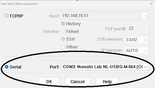
- Run the Tera term application. Select the port corresponding to the GPIO module in the “New connection” dialog and click OK.
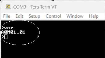
- Press ENTER key on the main window and a command prompt should appear as in the image below.
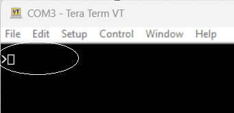
- Enter the command at the command prompt. Example “ver” command and response is in the image below.
5.2.Using Serial Terminal Software on Linux
5.2.1.GNU Screen
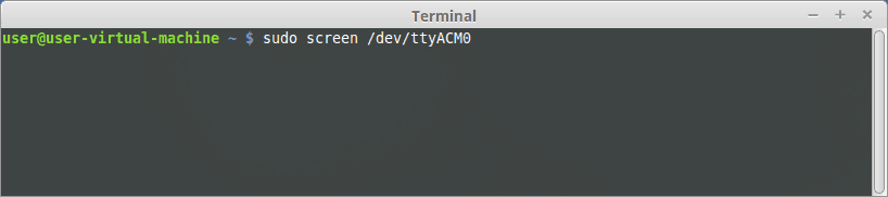
GNU Screen is a full-screen Window Manager that works with Serial Terminals as well. This makes GNU Screen a very handy tool to communicate with Numato Lab’s USB GPIO/Relay modules and other products. Please visit this document for details on how to install GNU Screen on your Linux machine. Run the command screen /dev/ttyACM0 as shown in the image below. Please don’t forget to replace the device name with device name retrieved from your system. Use sudo or set appropriate permissions for the device where necessary.
When the screen command is executed, you will be presented with an empty screen. Press ENTER key to see the command prompt. At the command prompt enter any command supported by the device. All commands must be completed by ENTER key press. Please see the list of available commands in the command set.
5.2.2.PuTTY
PuTTY is a free SSH/TELNET client that works with Serial Terminals as well. This makes PuTTY a very handy tool to communicate with Numato Lab’s USB GPIO/Relay modules and other products. Please visit this document for details on how to install PuTTY on your Linux machine. Start PuTTY by running the command putty at the terminal or double clicking the PuTTY icon. Use sudo or set appropriate permissions for the device where necessary. You will see a screen similar to the below image when PuTTY is started.
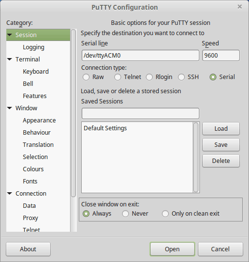
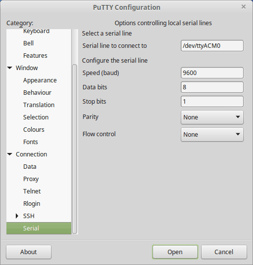
Leave settings as shown in the images above. Please don’t forget to replace the device name with device name retrieved from your system. Click Open button to start PuTTY session. PuTTY will start with an empty screen. Press ENTER key to show the command prompt. At the command prompt enter any command supported by the device. All commands must be completed by ENTER key press. Please see the list of available commands in the command set.
5.3.Using Serial Terminal Software on Mac OS X
5.3.1.The Screen Command
Mac OSX provides a built in command/program called screen that can be used to communicate with any serial device attached to a Mac device. The screen program is a light weight Terminal Emulator that is very easy to use. Run the command screen /dev/tty.usbmodem141141 as shown in the image below. Please don’t forget to replace the device name with device name retrieved from your system.
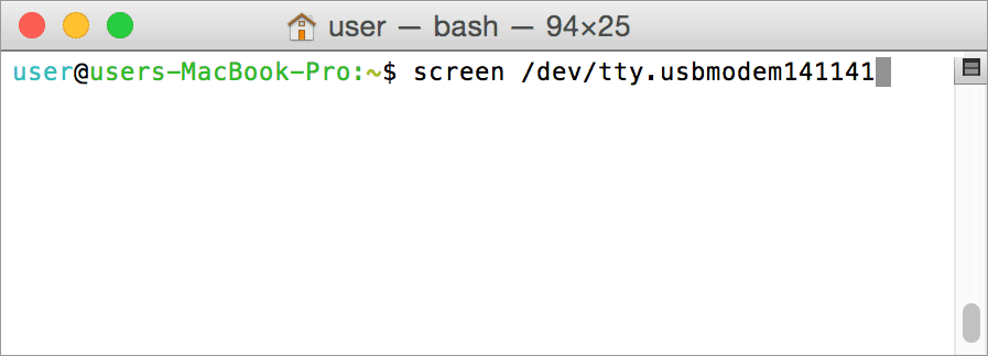
When the screen command is executed, you will be presented with an empty screen. Press ENTER key to see the command prompt. At the command prompt enter any command supported by the device. All commands must be completed by ENTER key press. Please see the list of available commands in the command set.
5.3.2.CoolTerm
CoolTerm is a free Serial Port Terminal application available for Mac OSX . Download and install CoolTerm on your Mac and run.
Select the appropriate serial port corresponding to your attached device. In the image below /dev/tty.usbmodem141141 is selected. Please don’t forget to select the correct port name corresponds to your device and leave all other settings as in the image below. Once all correct settings are selected, click the OK button to open the port.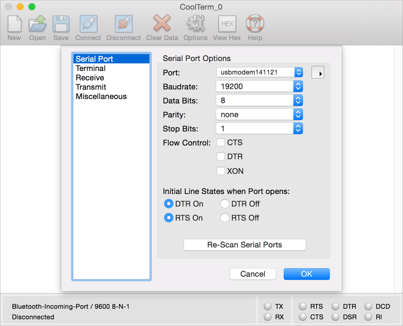
If the port opened successfully, you will be presented with an empty screen. Press ENTER key to see the command prompt. At the command prompt enter any command supported by the device. All commands must be completed by ENTER key press. Please see the list of available commands in the command set.
5.3.3.goSerial
goSerial is a free Serial Port Terminal application available for Mac OSX . Download and install goSerial on your Mac and run.
Select the appropriate serial port corresponding to your attached device. In the image below /dev/tty.usbmodem141141 is selected. Please don’t forget to select the correct port name corresponds to your device and leave all other settings as in the image below. Once all correct settings are selected, click the OK button to open the port.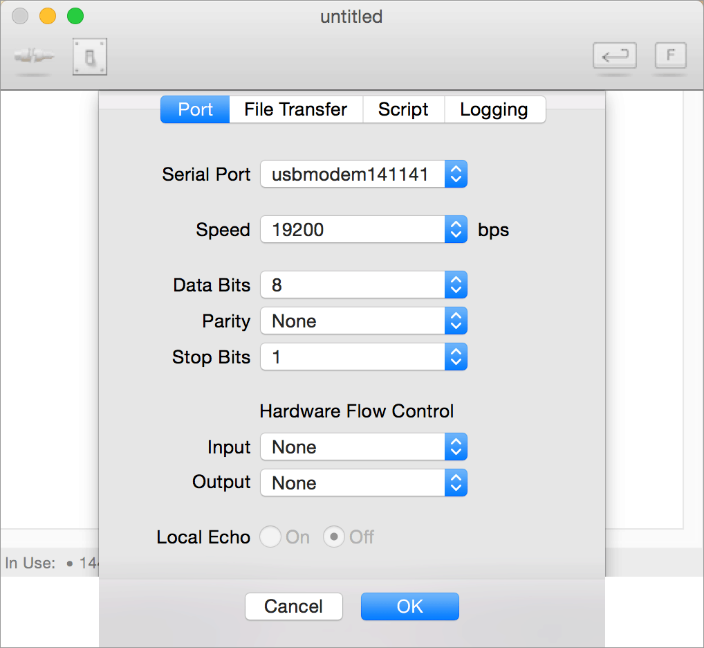
If the port opened successfully, you will be presented with an empty screen. Press ENTER key to see the command prompt. At the command prompt enter any command supported by the device. All commands must be completed by ENTER key press. Please see the list of available commands in the command set.
5.4.Using Serial Terminal Software on Android
5.4.1.USB Serial Terminal
Devices detected by Android can be controlled by sending commands using USB Serial Terminal Lite. Once connected to the device, enter commands to the command window and press the send button to execute. The commands and the results will be printed in the log window.
5.5.Using Custom Program and Script
This GPIO module can be controlled using custom programs written in many languages. Almost any language can be used as long as it supports some sort of serial communication method. Some of the supported languages include
- C/C++
- Visual Basic
- Visual Basic for Applications (Microsoft Office VBA)
- Perl
- Python
- JAVA
- And a lot more…
The APIs need to be used may be different depending on the target operating system even when the same language is used. For example when using C/C++ on Windows, Win32 Serial Communication APIs along with File IO APIs (CreateFile, ReadFile, WriteFile, etc…) needs to be used (see Microsoft Developer Page on serial communications). But when C/C++ is used on Linux operating system “termios”, APIs can be used for serial communication. Please refer to your compiler/language documentation for more details about serial port communication.
Specific details of programming may vary depending on the language and operating system of choice. But the fundamental steps for writing a program to control the GPIO module can be more or less the same. Here is the list of steps that you may need to follow while writing your own program.
- Open the serial port for communication.
- Set port parameters. Most of the parameters can be left to defaults except Flow Control, which needs to be set to “none”.
- To send a command to the module, use an API equivalent to write/writefile and pass the buffer/string containing the command. It is important to append Carriage Return (ASCII 13) to emulate the ENTER key.
- If return data is expected (Eg: “ver” command), try to read the characters from the serial port input buffer. APIs equivalent to Read/ReadFile can be used to read data from the module. Please note that the return data will include the command itself (since the module echoes everything back), the result, carriage return and the “>” symbol.
6.Technical Specifications
| Parameter | Value | Unit |
|---|---|---|
| Number of MOSFET outputs | 64 | |
| Digital circuit power supply voltage (USB or external) | 5 | V |
| Maximum current drawn by digital circuitry | 1 | A |
| Maximum switching voltage | 30 | V |
| Maximum load current per MOSFET | 1 | A |
| Maximum load per MOSFET(12V, 1A) | 12 | W |
| Operating Temperature | 0-80 | degrees Celsius |
| Connector details | ||
| Connector on board - Part Number | OSTOQ101251 | |
| Compatible plug – Part Number | 1840447 | |
NOTE!
Maximum load current (suggested) : 10A
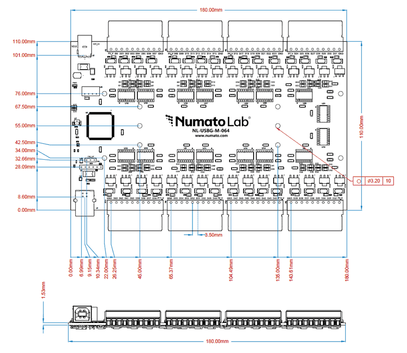
7.Mechanical Dimensions