Introduction
Numato Lab’s 2 Channel Programmable Relay Module is a feature rich product that can be programmed with Arduino IDE. The USB to Serial Chip FT232RL helps uploading sketches quickly to the board. This programmability gives this board ultimate flexibility compared to other relay modules where features depend on the preprogrammed firmware and offer limited customizability. The on board programmable relays, digital I/O’s, analog inputs, Real Time Clock(RTC) and Micro SD memory card slot makes this module useful for learning as well as making sophisticated applications.
Applications
- Home Automation
- Lighting Control
- Garden Equipment Control
- Industrial Automation
- Test Fixtures
- DIY and Hobby
- Relay operation by RTC circuit
- Data logging
Board Features
- Atmega328p Micro controller with 32KBytes flash memory
- Arduino IDE Compatible
- FT232RL chip for USB to Serial Interface
- 2 SPDT 12V Mechanical Relays
- 4 Digital I/O’s
- 2 PWM outs
- 4 Analog Inputs
- I2C Interface
- Real Time Clock(RTC) via I2C Interface
- Battery backup for RTC
- Micro SD Card Slot via SPI Interface
- Indication LED for Power, TX, RX and Relays
- ISP for doing custom boot loader
- 16 MHz Crystal
- USB mini Connector for Connecting with PC
This product is compatible with the following operating systems.
- Windows XP and later
- Linux
- Mac
- And any other operating system that supports USB CDC devices.
This module has two on board SPDT 12V mechanical relays and associated drivers capable of controlling a large number of devices including lamps, motors, locks etc…(Please see recommendations for using this product with inductive loads elsewhere in this document). By default the board burned with Arudino Duemilanove w/ Atmega328 boot loader using the Arudino IDE. This module also includes Digital I/Os(multiplexed with PWM outputs), analog inputs, I2C Interface, Real Time Clock using DS1307, Micro SD Card Slot for storage, these can be accessed over USB interface and program easily with Arduino IDE for extended functionality. The module communicates with host PC over full speed USB link. When connected to PC, the module will appear as a serial port in Windows Device Manager (or a serial tty device in Linux and Mac).
How to Use 2 Channel Programmable Relay Module
Components/Tools Required
Along with the module, you may need the items in the list below for easy and fast installation.
1. USB A to Mini B cable.
2. Medium size Philips screw driver.
3. 12V Power supply.
Connection Details
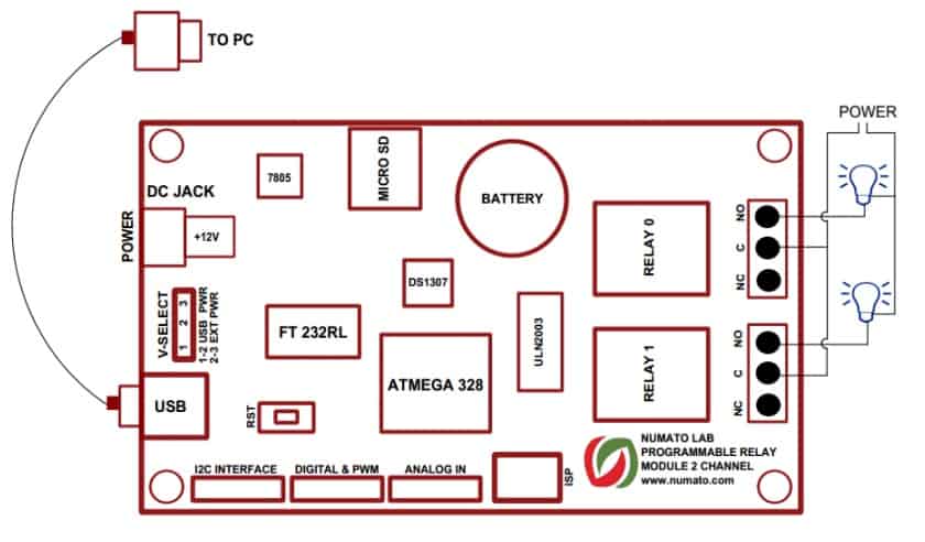
Connection Diagram
Above image shows basic connection diagram that can be used in most of the situations. The connection diagram is same for both AC and DC loads. Please make sure to use a freewheeling diode or snubber circuit if the load is inductive. More details about using inductive loads is available elsewhere in this document. Use a USB A to Mini B cable for connecting with PC. It is important to make sure that the wires used to connect loads are sufficiently rated to handle expected load current. Exercise caution while working with high voltages. Short circuits can cause damage to the module and the PC. The following sections identify individual connections in detail.
USB Interface
The on board full speed USB controller that helps a PC/Linux/Mac computer to communicate and control this module seamlessly. Use a USB A to Mini B cable to connecting with a PC. By default, the logic section of the module is powered from USB so make sure not to overcrowd unpowered USB hubs. Visit http://numato.com/cables-accessories to buy cables and accessories for this product
Relay Contacts
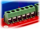 All contacts on each relay is available externally on screw terminals for easy user access. The relays are rated for AC and DC supply voltages. Please see the electrical parameter table for more details. Each relay has three contacts(C, NO and NC). C is the common terminal and is used in both normally open and normally closed positions. The contacts NC and C will be connected when the relay is turned off and will be disconnected when relay is turned on. And vice versa, the contacts C and NO will be disconnected when relay is turned off and will be connected when the relay is turned on. Table below summarizes possible relay contact positions.
| Relay State | Connection between NC and C | Connection between NO and C |
|---|---|---|
| OFF | Close | Open |
| ON | Open | Close |
DC Power Supply
This module uses external +12V power supply to function properly. External +12V supply can be given through the DC jack on the board. Logic circuit can be powered from USB or on board 5V regulator from external +12V. The logic circuit uses +5V supply and the relay coils uses +12V supply. By default the board is configured to use +12V supply. So an external +5V power is not required unless USB port is unable to supply enough current. In most cases USB ports are capable of providing enough current for the module. The +12V supply for the relay coils is not optional and the relay will not switch without this supply. Any off the shelf 12V DC power supply can be used for this purpose. Make sure to connect the power supply in correct polarity. If for any reason, an external 5V power supply needs to be used for the logic section of the module, the Jumper V-Select should be configured properly before connecting the power supply. Please refer to the marking on the board for more details.
On Board Relays
The board has two 12VDC SPDT mechanical relays that can switch up to 10A DC/12A AC. The popular ULN2003 IC is used to drive the relays individually, the inputs of the ULN2003 IC are connected to the Atmega328P digital pins(PD2,PD3) and the outputs of the ULN2003 IC are connected to relays(0, 1) respectively. Writing HIGH to these digital pins makes corresponding relay to ON and vice versa writing LOW to these digital pins makes corresponding relay to OFF. Sample sketch for testing Relay is available in our website. The table below summarizes the digital I/O’s used for relay triggering.
| PROGRAMMABLE RELAY MODULE | ARUDINO UNO PIN | Atmega328P |
|---|---|---|
| Relay 0 | 2 | PD2 |
| Relay 1 | 3 | PD3 |
Digital I/O's
In addition to on board relays, this board has four Digital IO pins that can be used for various custom applications. Digital IO 5th and 6th are multiplexed with PWM outputs. All IO pins support 5V TTL signals. In output mode, each DIGITAL IO can source up to 40mA. So no additional circuitry is needed to drive regular LED’s. A 470 Ohms series resistor is recommended for current limiting when connecting LED to a DIGITAL IO. Sample sketch for testing Digital I/O’s is available in our website. The table below summarizes the Digital and PWM input positions on the header.
| PROGRAMMABLE RELAY MODULE | ARUDINO UNO PIN | Atmega328P | PWM |
|---|---|---|---|
| 4 | 4 | PD4 | NO |
| 5 | 5 | PD5 | YES |
| 6 | 6 | PD6 | YES |
| 7 | 7 | PD7 | NO |
Analog Input
The board have 4 analog input pins multiplexed with ADC. Analog inputs can read voltages at any level between 0 to 5 volts. It is recommended to use a series resistor to protect the input from stray voltages and spikes. The internal Analog To Digital converter supports 10 bits resolution which is adequate for most applications. Sample sketch for testing Analog In is available in our website. The table below summarizes the Analog and ADC input positions on the header.
| PROGRAMMABLE RELAY MODULE | ARUDINO UNO PIN | Atmega328P |
|---|---|---|
| A0 | A0 | PC0/ADC0 |
| A1 | A1 | PC1/ADC1 |
| A2 | A2 | PC2/ADC2 |
| A3 | A3 | PC3/ADC3 |
Real Time Clock input
The DS1307 serial real-time clock (RTC) with low power, full binary-coded decimal (BCD) clock/calendar plus 56 bytes of NV SRAM. Address and data are transferred serially through an I2C, bidirectional bus. The clock/calendar provides seconds, minutes, hours, day, date, month, and year information. The end of the month date is automatically adjusted for months with fewer than 31 days, including corrections for leap year. The clock operates in either the 24-hour or 12-hour format with AM/PM indicator. The chip has a built-in power-sense circuit that detects power failures and automatically switches to the backup supply. Timekeeping operation continues while the part operates from the backup supply. Sample sketch for testing RTC, RTC with Relay is available in our website. The table below summarizes the I2C pins used for RTC functioning.
| PROGRAMMABLE RELAY MODULE | ARUDINO UNO PIN | Atmega328P |
|---|---|---|
| SDA | A4 | PC4/ADC4 |
| SCL | A5 | PC5/ADC5 |
Micro SD Card Slot
The Micro SD uses SPI Communication which takes place on digital pins PB3(11), PB4(12), and PB5(13) of Atmega328P with MOSI, MISO, & SCK. The CS pin is connected to the PB0(8) of Atmega328 digital pin. Please refer the following link before you are start working with Micro SD Card http://arduino.cc/en/Reference/SDCardNotes. Arduino having SD card library. Once the board is connected try the example codes in Arduino SD library. The example ‘info’ will gives the details of SD card inserted. Sample sketch for testing Micro SD Card is available in our website.
The table below summarizes the SPI pins used for Micro SD Card functioning.
| PROGRAMMABLE RELAY MODULE | ARUDINO UNO PIN | Atmega328P |
|---|---|---|
| MOSI | 11 | PB3/MOSI |
| MISO | 12 | PB4/MISO |
| SCK | 13 | PB5/SCK |
| CS | 8 | PB0 |
I2C Interface
Using this interface the board can communicate with a wide variety of chips that support I2C communication. Interfacing with various shields, sensors etc are major applications of this. The table below summarizes the I2C input positions on the header. Please aware that the I2C interface pins and RTC operations can’t use simultaneously since both are using I2C communication.
| PROGRAMMABLE RELAY MODULE | ARUDINO UNO | Atmega328P |
|---|---|---|
| SDA | A4 | PC4/ADC4 |
| SCL | A5 | PC5/ADC5 |
In System Programmer(ISP)
ISP on the board can be act as AVR ISP. This feature on the board helps to burn boot loader on AVR(Atmega168/Atmega328). For additional information on burning the boot loader, see this link http://arduino.cc/en/Tutorial/ArduinoISP. The ISP pins PB3,PB4,PB5 can also be used as digital I/O’s when it is not using for Micro SD Card since it shares the same pins for SPI communication.
| PROGRAMMABLE RELAY MODULE | ARUDINO UNO PIN | Atmega328P |
|---|---|---|
| GND | GND | GND |
| PB4 | 12 | PB4/MISO |
| VCC | 5V | 5V |
| RST | RESET | RESET |
| PB3 | 11 | PB3 |
| PB5 | 13 | PB5 |
Driver Installation
Installing on Windows
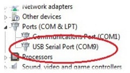 This product requires a driver to be installed for proper functioning when used with Windows. The driver package can be downloaded from http://www.ftdichip.com/FTDrivers.htm. To install the driver, unzip the contents of the downloaded driver package to a folder. Attach USB cable to the PC and when asked by Windows device installation wizard, point to the folder where driver files are present. When driver installation is complete, the module should appear in Windows Device Manager as a serial port (see the picture on the right). Note down the name of the serial port (COM9). This information is required to control the module from the PC.
The following video demonstrates how to install the driver on Windows 10.
Installing on Linux
To use this product with Linux, USB CDC driver needs to be compiled in with the kernel. Fortunately, most Linux distributions (Ubuntu, Redhat, Debian etc..) has this driver pre-installed. The chances of you requiring to rebuild the kernel to include the USB CDC driver is very slim. When connected to a Linux machine, this product should appear as a serial port in the /dev directory. Usually the name of the device will be “ttyACMx” or similar. The name may be different depending on the Linux distribution you have.
Installing on Mac
Similar to Linux, Mac operating system comes with the required drivers pre-installed. When connected to a Mac computer, the device should appear as a serial port.
Powering up Programmable Relay Module 2 Channel
1. Select the appropriate jumper selection on the V-Select (Default jumper settings should work in most situations).
2. Connect +12V DC Supply to the DC-Jack (Optional if you are not planning to use relays).
3. Connect the board to the host PC using USB Cable.
4. Install driver when asked.
5. Download the demo code for the relay from http://numato.com/ 2-channel-programmable-relaymodule.
6. Open the code in Arduino IDE (Download link. http://arduino.cc/en/main/software).
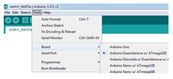
7. Select the Board “Arduino Duemlanove w/Atmega328 board” from tools menu. (see the image below).
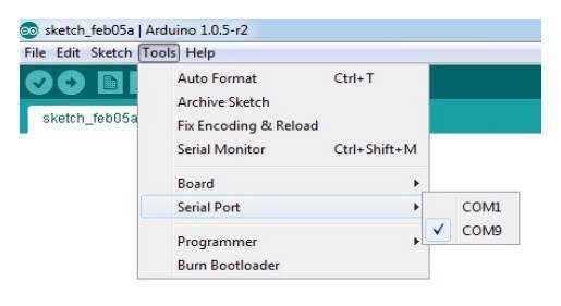
8. Also select the serial port from the tools menu (see the image below).
9. Compile and upload code to the board.
10. Individual relays can be controlled by sending simple numbers to the Arduino serial monitor. The
table below summarizes the input number to serial monitor and corresponding state change of relay.
These commands will work only if the relay control sketch is uploaded to the board.
| RELAY | command | Relay state |
|---|---|---|
| Relay 0 | 01 | on |
| Relay 1 | 11 | on |
| Relay 0 | 00 | off |
| Relay 1 | 10 | off |
Additional Information
Analog to Digital Converter
2 Channel Programmable Relay Module do support Analog to Digital Conversion on some of the IO terminals. A list of analog input pins that supports analog function in this product is listed in Analog Input in this document. There is no special command is required to execute to switch between analog and digital mode. The input voltage range of the ADC is 0 – VDD (this product uses 5V power supply, so the range will be 0 – 5V). The result will be returned as a number starting at zero and ending at 1023. Zero indicates zero volts at the ADC input and 1023 indicates VDD (5V for this product) at ADC input.
Using DIGITAL I/Os with Switches
It is possible to read the position of a switch that is connected to a DIGITAL IO. A SPST or SPDT switch is recommended to use with DIGITAL IOs. Push switches do maintain the contacts closed only for a very short time so using them is discouraged. The fundamental idea of using a switch with DIGITAL IO is to have the switch cause a voltage level change at the DIGITAL IO pin when pressed. Usually this is achieved by using an external pull-up resistor along with the switch. The pull up resistor is connected between the DIGITAL IO and VDD and the switch is connected between the DIGITAL IO and ground. When the switch is not pressed, the pull-up resistor will cause the DIGITAL IO to stay at VDD voltage level. When the switch is pressed, the DIGITAL IO is short circuited to ground and stays at zero voltage. This change in voltage and thus the position of the switch can be read using “DIGITAL IO read” command. Please see the recommended connection diagram below.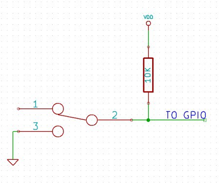
Using Relay Modules with Inductive Loads
Using relay modules with inductive loads It is important to take additional care when using relays with inductive loads. An inductive load is pretty much anything that has a coil and works based on magnetic principles like Motors, Solenoids and transformers. Inductive loads produce back emf when the magnitude of the load current changes. The back emf can be in the order of tens or even hundreds of voltage (See this Wikipedia article http://en.wikipedia.org/wiki/Counter-electromotive_force). This effect is most severe when power is disconnected from inductive load because the rate of change of current is maximum at that point. Even though the back emf lives only for a very short time (a few milliseconds) it can cause sparks between the relay contacts and can deteriorate the contact quality over time and reduce the life span for the relays considerably.
So it is important to take countermeasures to suppress the back emf to acceptable levels to protect relay contacts. Usually this requires connecting electronic devices in parallel with the load such that they absorb the high voltage components generated by the load. For solenoids, connecting a diode (fast switching diode is recommended) in parallel to the load (in reverse direction to the load current) is very effective. A diode used for this purpose is usually called a freewheeling diode. Please see the diagram on the right for connection details.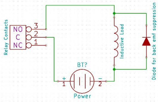
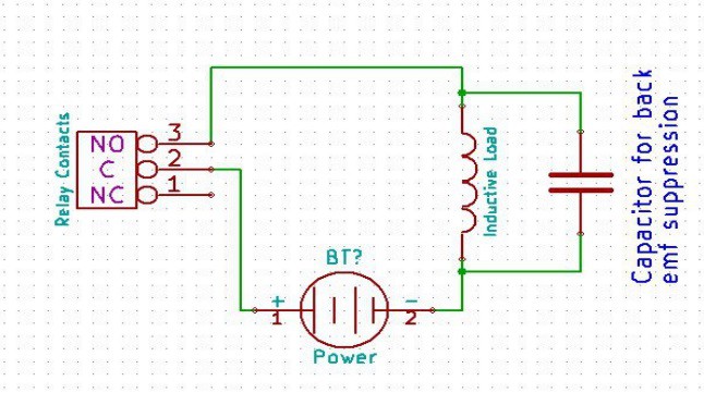
A capacitor with proper rating is recommended for protecting the relay contacts when a motor is used as load. The capacitor should be rated enough to withstand the back emf that is generated by the motor. Please see the diagram below for connection details.
Please note that the relay modules are NOT shipped with back emf suppression devices pre-installed. The exact kind of suppression device and the parameters of the selected device can vary depending on the load itself. Some of the parameters that affects the suppression device selection are the inductance of the load, power supply voltage, load current, physical size/structure of the load etc.. It is obvious that it is impossible for us to predict these parameters and design required back emf suppression device and incorporate that on the board. So we believe this is a task best left to the module user. There is an excellent article on designing back emf suppression on Wikipedia at http://en.wikipedia.org/wiki/Flyback_diode
Technical Specifications
| Parameter | Value | Unit |
|---|---|---|
| Number of relays | 2 | |
| Number of Digital I/Os | 4 | |
| Digital I/Os(multiplexed with PWM outputs) | 2 | |
| Number of Analog Inputs | 4 | |
| Digital circuit power supply voltage (USB or external) | 5 | V |
| Maximum current drawn by digital circuitry | 200 | mA |
| IO Specifications | ||
| Maximum IO source current | 40 | mA |
| Maximum IO sink current | 40 | mA |
| DIGITAL IO input low voltage | 0.8 | V |
| DIGITAL IO input high voltage | 5 | V |
| DIGITAL IO output low voltage | 0 | V |
| DIGITAL IO output high voltage | 5 | V |
| ADC Specifications | ||
| Resolution | 10 | bits |
| Full scale range | 0 – VDD | V |
| Reference voltage | VDD | V |
| Recommended Impedance of Analog Voltage Source | 2.5 | KΩ |
| Relay Specifications | ||
| Nominal relay coil voltage | 12 | V |
| Nominal coil power consumption (per relay) | 360 | mW |
| Relay contact material | Silver Alloy | |
| Contact rating | 1C: 7A 240VAC/ 10A 120VAC | |
| Maximum switching voltage | 250VAC/ 30VDC | |
| Maximum switching current | 10 | A |
| Maximum switching power | 2770VA/ 240W | |
| Contact resistance (initial) | 100 Min at 6VDC 1A | mΩ |
| Life expectancy (Electrical) | 100,000 | Operations |
| Life expectancy (Mechanical) | 10,000,000 | Operations |
| Nominal insulation resistance | 100 Min at 500VDC | MΩ |
| Maximum switching on response time | 10 | mS |
| Maximum switching off response time | 5 | mS |
| Real Time Clock(RTC) Specifications | ||
| Real Time Clock Chip | DS1307 | |
| Supply Voltage | 5 | V |
| V-BAT Battery Voltage | 3 | V |
| Battery Back-up current | 500 | nA |
| Oscillator frequency | 32 | KHz |
| Communication Interface | I2C | |
| Micro SD Card Slot Specifications | ||
| Supply Voltage | 3.3 | V |
| Communication Interface | SPI | |
| Card Slot type | Push through | |
Frequently Asked Questions (FAQs)
Q. What are the serial parameters I need to use when communicating with this board?
A. Since this module uses USB as the underlying transport mechanism, most of the serial parameters do not affect the communication. You can leave all parameters to any legal value (Eg: 2400, 4800, 9600 etc… for baud rate) except Flow control. Flow control needs to be set to “None”.
Q. Where do I find driver for this product?
A. http://www.ftdichip.com/FTDrivers.htm Visit and navigate driver page. There will be a link to download windows driver. Linux and Mac does not require driver installation since in most cases they are shipped with the driver pre-installed.
Q. The DIGITAL IO looses its previously set value when trying to read the status. Why it is so?
A. When a DIGITAL IO is to output a value (high/low), that particular DIGITAL IO is put to output mode. When you are trying to read the DIGITAL IO, it needs to be put in input mode. In input mode, the DIGITAL IO will go to high impedance state and thus looses the previously set value.
Q. What is the connector marked as ISP on this module?
A. This connector is used to program the on-board micro controller. This connector is primarily intended for factory use.
Q. I need a customized version of this product, can Numato do the customization for me?
A. Yes, we can definitely do customization but there may be minimum order requirements depending on the level of
customization required. Please write to sales@numato.com for a quote.
Q. Where can I buy this product?
A. All Numato products can be ordered directly from our web store http://www.numato.com. We accept major credit cards and Paypal and ship to almost all countries with a few exceptions. We do have distributors in many countries where you can place your order. Please find the current list of distributors at http://numato.com/distrib.
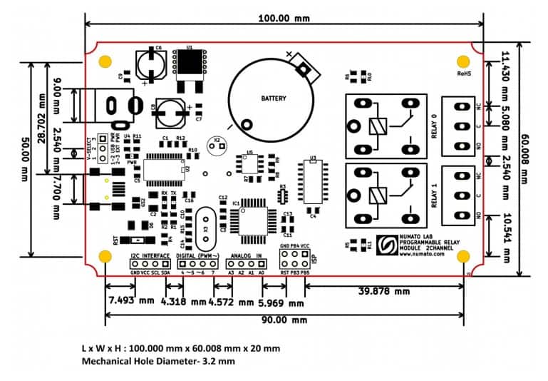
Mechanical Dimensions