Introduction
Welcome to the world of electronics, where circuits come alive and innovation knows no bounds! In this introduction, we’ll embark on a journey through electronics. Electronics forms the foundation of modern technology, encompassing the study and application of electrical circuits and devices. From smartphones to satellites, electronics power our interconnected world, driving innovation and shaping the future.
To wield the full potential of FPGAs and Verilog, we turn to Vivado—the industry-leading software suite from Xilinx. Vivado offers a comprehensive set of tools for designing, synthesizing, and implementing FPGA projects with ease and efficiency. From schematic entry to high-level synthesis, Vivado empowers designers to turn concepts into reality and push the boundaries of digital innovation. This tutorial is not meant to be an in-depth study about Verilog or FPGAs or anything. Still, just a guide to walk you through different basic things you need to know to design a simple digital circuit in Verilog, simulate it, and implement it on hardware. Vivado version 2023.2.1 is used to demonstrate examples.
Understanding FPGAs
Imagine a digital playground where you have the power to design and implement your digital circuits with unprecedented flexibility and agility. That’s precisely what an FPGA offers. Unlike traditional fixed-function chips, FPGAs are blank slates that can be programmed and reprogrammed for many tasks, making them ideal for prototyping, rapid development, and specialized applications.
Why Choose FPGAs?
The allure of FPGAs lies in their versatility and adaptability. Here’s why they are favored in various industries:
- Flexibility: FPGAs enable you to create custom digital circuits tailored to your specific requirements, from simple logic gates to complex processing units.
- Speed: With their inherent parallelism, FPGAs can execute tasks at blazing speeds, making them suitable for high-performance computing and real-time applications.
- Cost-Effectiveness: For low to medium-volume production, FPGAs offer a cost-effective alternative to custom ASICs, eliminating the need for expensive mask sets.
- Prototyping Power: FPGAs serve as invaluable tools for ASIC prototyping, allowing designers to iterate and refine their designs before committing to silicon.
What is Verilog?
Verilog is a hardware description language (HDL) used in digital circuit design. It provides engineers with a means to describe the behavior and structure of electronic systems, from basic logic gates to complex processors, using a text-based syntax. In simpler terms, Verilog is like a language for writing instructions that define how electronic circuits should function. These instructions can include specifying how signals flow through the circuit, how logic gates combine to perform operations, and how the entire system responds to different inputs.
In the late 1970s and early 1980s, as digital electronics were becoming increasingly prevalent, engineers faced a growing need for a standardized and efficient way to describe and design digital circuits. At the time, hardware design was primarily done using schematic diagrams, which became cumbersome and impractical as designs grew in complexity. In response to these challenges, a team at Gateway Design Automation, led by Phil Moorby, began developing a hardware description language that would streamline the process of digital design. This language would enable engineers to specify the behavior and structure of digital circuits using text-based descriptions, rather than relying solely on schematics. The result of their efforts was Verilog, which was first released in 1985 as a proprietary language by Gateway Design Automation. Verilog quickly gained traction within the electronics industry due to its simplicity, flexibility, and powerful features.
Learning Verilog is not that hard if you have some programming background. VHDL is also another popular HDL used in the industry extensively. Verilog and VHDL share more or less same market popularity, but I chose Verilog since it is easy to learn and its syntactical similarity to C language. Once you are comfortable with Verilog, it should be easy to learn VHDL as well. Want to read more about Verilog? Check out this wiki page (http://en.wikipedia.org/wiki/Verilog) or check this tutorial (http://www.asic-world.com/verilog/index.html).
Getting Started with Mimas S7 Lite
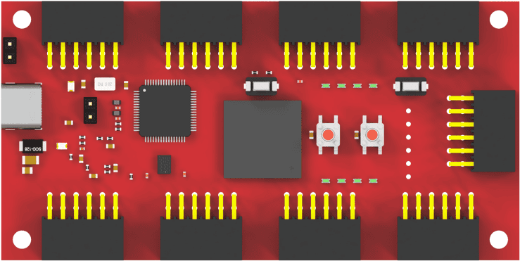
Now, let’s turn our attention to the Mimas S7 Lite FPGA board—a beginner-friendly platform designed to ignite your passion for FPGA development. Here’s what you need to begin your journey:
- Hardware: The Mimas S7 Lite FPGA board, equipped with a Xilinx Spartan-7 FPGA
- Software: Xilinx Vivado Design Suite, a comprehensive toolchain for designing, synthesizing, and implementing FPGA projects.
Starting Your First Project
With the groundwork laid, it’s time to start your FPGA project with the Mimas S7 Lite board. Here’s a glimpse of what awaits:
- Setting up the Environment: Configure your development environment and establish communication with the Mimas S7 Lite board.
- Writing Verilog Code: Craft your digital masterpiece using Verilog, a hardware description language akin to writing software in C.
- Synthesizing and Implementing: Transform your Verilog code into a tangible design by synthesizing and implementing it on the FPGA.
- Testing and Debugging: Validate the functionality of your project and fine-tune it using debugging techniques to ensure optimal performance.
