
Introduction
Numato Lab’s ZRX16/32/64 Channel DIN Rail compatible Modbus RTU/TCP Relay Module with Digital IO and Analog Inputs offers great flexibility at lower cost. Ease of use and wider operating system compatibility are the primary goals behind this product’s design. Built-in USB to serial conversion allows the module to be used without any USB specific knowledge. Industry-standard Modbus protocol support allows this product to be used with most automation software that supports Modbus. For power users, this module can be controlled by writing programs in various programming languages of their choice.
Features:
- Industry-standard Modbus protocol support
- DIN Rail compatible
- 16/32/64 Mechanical Relay with contact rating up to 250V/5A each
- 8 TTL (3.3V) compatible Digital IOs
- 8/6 analog inputs with 12-bit resolution (multiplexed with Digital IOs)
- USB interface with CDC support. As easy as using a serial port, no USB knowledge required
- Fully isolated design with optocouplers and built-in DC-DC converter
- Relay contacts available on easy to access screw terminals
- 12V external power supply (included)
- Can be controlled by using industry-standard automation applications or custom applications
Some of the possible uses of this module include
- Home Automation
- Lighting Control
- Garden Equipment Control
- Industrial Automation
- Test Fixtures
- DIY and Hobby
This product is compatible with the following operating systems:
- Windows XP and later versions (Windows 7, 8/8.1, 10 and future versions)
- Windows 7 Embedded and later
- Linux
- Mac OS X
- Android
- Or any other operating system that supports USB CDC devices.
And these are some of the languages that can be used for programming:
- C/C++
- Visual Basic (VB6, VB2008, VB2010 express and other editions)
- Visual Basic for Applications (Microsoft Office VBA)
- Perl
- Python
- JAVA
- Android
- JavaScript (Node.js)
- LabVIEW
- And many more…
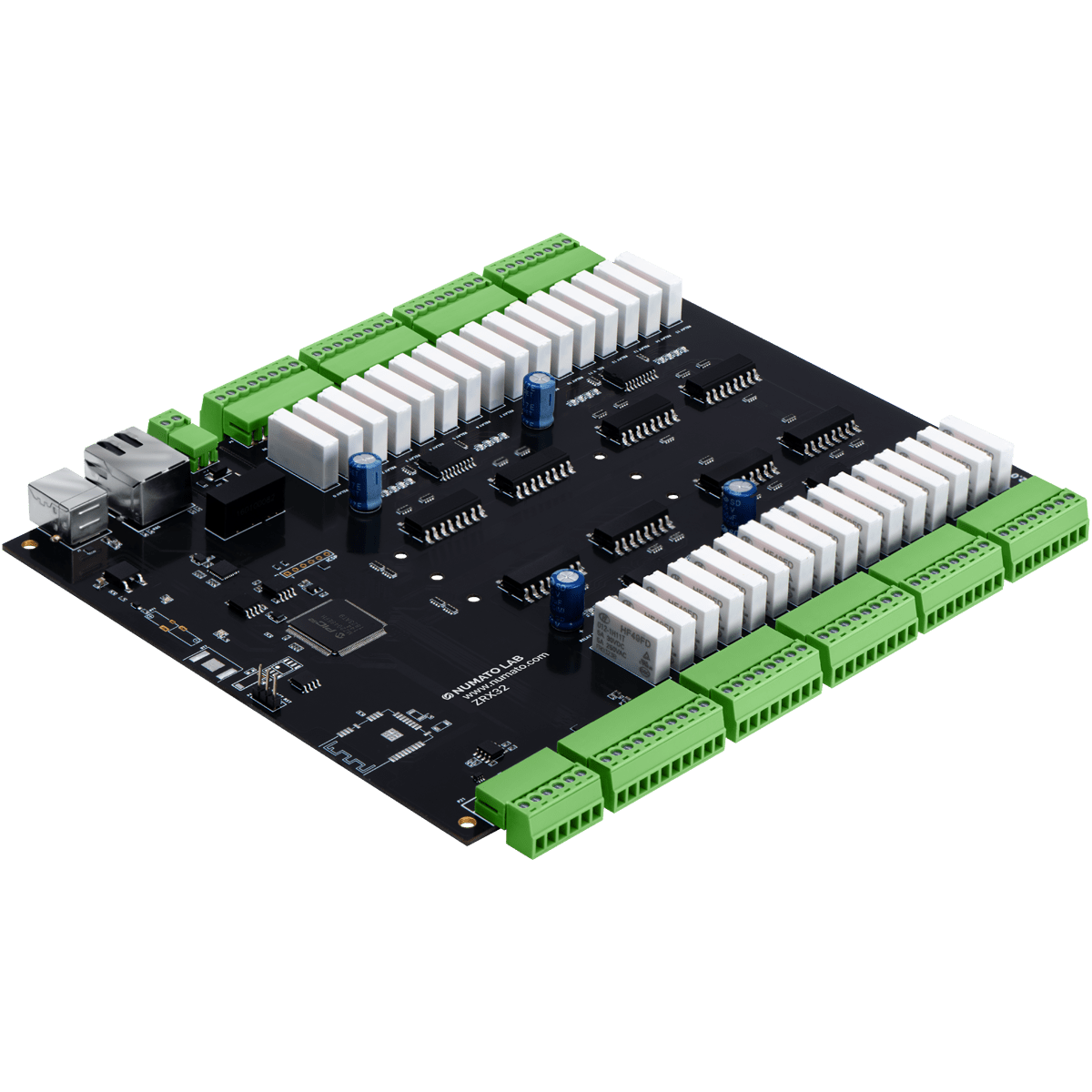
This product has 16/32/64 onboard relays and associated drivers capable of controlling a variety of devices including lamps, motors, locks etc… (Please see recommendations for using this product with inductive loads elsewhere in this document). This module also includes General Purpose I/Os, and analog inputs (multiplexed with GPIOs) that can be accessed over USB interface for extended functionality. The module communicates with host PC over full speed USB link, RS485, and Ethernet interface. When connected to PC using USB/RS485, the module will appear as a serial port in Windows Device Manager (or a serial tty device in Linux and Mac).
How to Use Prodigy Relay Modules
Using this product is very easy, thanks to supporting industry-standard Modbus protocol, the RTU and the TCP/IP network interface that allows the device to be used with most readily available Data Communication Test Software like QModMaster. This document has more information about using this device with the following software. But in no way limited to this software though.
- Windows
- QModMaster
- Radzio! Modbus Master Simulator
- Linux
- Coming soon
- Coming soon
- Mac OS X
- Coming soon
Using this product with RTU involves the following simple steps.
- Connect the device using a USB A to B cable or a USB to RS485 converter to the host system
- Install driver if applicable
- Open the COM port corresponding to the device using software that supports Modbus
- Read/Write Coils and Registers
- Optionally write a script or custom application to automate your task
Using this product with TCP/IP Network interface involves the following steps.
- Connect the device using a CAT 5e Ethernet Cable(Straight through cable) to the host system
- Connect to the IP corresponding to the device using software that supports Modbus TCP
- Read/Write Coils and Registers
- Optionally write a script or custom application to automate your task
All aspects of the above steps are covered in the following sections including step by step demonstration.
Components/Tools Required
Along with your Prodigy ZRXxx device, you will need the items in the list below for easy and fast installation.
1. USB A to B cable (Included) – For USB Interface.
2. CAT 5e Ethernet Cable(Straight through cable) – For Ethernet Interface.
3. USB to RS-485 Converter – For RS485 Interface.
4. 12V Power Supply (Included).
5. Medium size Philips screwdriver.
Connection Details

The picture above shows a basic connection diagram that can be used in most of the situations. The connection diagram is the same for both AC and DC loads. Please make sure to use a freewheeling diode or snubber circuit if the load is inductive. More details about using inductive loads are available elsewhere in this document. Use a USB A to B cable to connect the unit to a PC. It is important to make sure that the wires used to connect loads are sufficiently rated to handle the expected load current. Exercise caution while working with high voltages. Short circuits can cause damage to the module and the PC. The following sections identify individual connections in detail.
USB Interface
 The onboard full-speed USB controller helps a computer to communicate and control this module seamlessly. Use a USB A to B cable (Included) to connect the unit to a PC. The device can be connected directly to the host PC or connected through a compatible USB hub. For high-performance system integration, it is recommended to connect the device directly to one of the root ports.
RS485 Interface
A USB to RS485 converter helps a computer to communicate and control this module seamlessly. Use a USB to RS485 converter to connect the unit to a PC. The device can be connected directly to the host PC or connected through a compatible USB hub. For high-performance system integration, it is recommended to connect the device directly to one of the root ports.
Ethernet Interface
 The onboard Ethernet port supports Ethernet 10Mbps transmission speed that helps a computer to communicate and control this module easily. There are two basic network configurations for this board/can be used in two ways.
- Direct connection to Local Area Network(LAN) via common straight-through Ethernet cable.
Eg: Connecting the module to a switch in a network. - Direct connection to a PC through a cross over Ethernet cable. Eg: Connecting the module directly to the PC. Some PC/Laptops can detect and adapt to the cable type. In such situations, a straight-through cable also can be used.
Relay Contacts
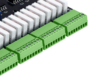 Prodigy ZRX devices have 16/32/64 mechanical relays that can switch up to 5A of current. IN and OUT connections to the relays are available externally on screw terminals for easy user access. The relays are rated for AC and DC supply voltages. Please see the electrical parameter table for more details. Each relay has two contacts(IN, OUT. The contacts IN and OUT will be connected when the relay is turned ON and will be disconnected when the relay is turned OFF. The table below summarizes possible relay contact positions.
| Relay State | Connection between IN and OUT |
|---|---|
| OFF | Open |
| ON | Close |
GPIO/Analog Inputs
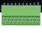 In addition to the onboard relays, this Prodigy ZRX device has 8/6 General Purpose IO pins that can be used for various custom applications. Some of these or all of these pins depending on the device can be used as Analog to Digital Converter inputs as well. All IO pins support 3.3V TTL signals and the ADC input range is 0 to +3.3V. The ADC can acquire the analog signal at the resolution of 12 bits per sample. It is recommended to use a series resistor with the GPIO/ADC pins when interfacing with other circuits. In output mode, GPIOs can source up to 20mA. So no additional circuitry is needed to drive regular LEDs. A 470 Ohms series resistor is recommended for current limiting when connecting LED to a GPIO.
In contrast to GPIOs, Analog inputs can read voltages at any level between 0 to 3.3V. It is recommended to use a series resistor to protect the input from stray voltages and spikes. The internal Analog to Digital converter supports 12 bits resolution which is adequate for most applications. The table below summarizes the GPIO and Analog to Digital Converter input positions of ZRX16/32/64 on the screw terminals.
| GPIO | ZRX16/32 | ZRX64 |
|---|---|---|
| IO0 | ADC0 | ADC0 |
| IO1 | ADC1 | ADC1 |
| IO2 | ADC2 | ADC2 |
| IO3 | ADC3 | ADC3 |
| IO4 | ADC4 | ADC4 |
| IO5 | ADC5 | ADC5 |
| IO6 | ADC6 | - |
| IO7 | ADC7 | - |
| GND | GND | GND |
DC Power Supply
This product requires an external 12V power supply to function. The power supply unit required is included with the product. Connect the power supply to the connector on the product marked as +12V power. This product uses single power supply for the digital circuitry and the relay coils. An internal isolated DC-DC converter and a set of optocouplers ensure galvanic isolation between the digital circuitry and the relay coil driver circuitry.
Driver Installation
Installing Numato Lab CDC Driver - Windows Desktop and Server Editions
The driver package for Numato Lab’s Prodigy models can be downloaded from the product page at https://numato.com. To install the driver, unzip the contents of the downloaded driver package to a folder. Attach the USB cable to the PC and when asked by Windows device installation wizard, point to the folder where driver files are present. When the driver installation is complete, the module should appear in Windows Device Manager as a serial port. The picture below shows a Prodigy ZRX64 visible in Windows Device Manager. For other ZRX devices, the name will be different but how the device is displayed and used is exactly the same.
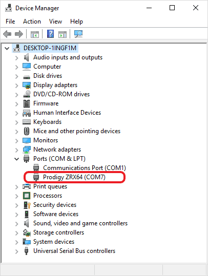
Note down the name of the serial port (COM1, COM2, etc..). This information is required to control the module from the PC.
You may notice that the driver package does not come with a .sys or .exe file as most driver packages do and are expected to be that way. The driver binary necessary in this case is shipped with all copies of Windows Desktop/Server editions and gets installed automatically while Windows is installed for the first time. The .inf and .cat files present in the driver package downloaded from http://numato.com merely associate this pre-existing driver with the attached Numato Lab device.
The following video demonstrates how to install the driver on Windows 10.
Installing on Windows Embedded Editions
Windows Embedded editions do not install the infrastructure necessary for USB CDC by default in favor of a smaller footprint. This will cause the driver install to fail unless the necessary files are manually installed prior to installing the driver. Please follow the steps below to install the prerequisites and driver correctly. These steps are tested on Windows 7 Embedded Edition. The installation procedure may vary for other versions of Windows Embedded. Please contact Microsoft for more information.
- Locate winemb-inf-mdmcpq.cab on Win 7 Embedded DVD/ISO image
- Copy winemb-inf-mdmcpq.cab to a folder Ex: C:Temp
- Run command DISM.exe /online /Add-Package /PackagePath:C:Temp
- Wait for Windows to restart (Restart machine manually if DISM does not restart the machine automatically)
- After the reboot is complete, plug the device to a USB port and install driver normally (Driver is available for download at the product page)
Installing on Linux
To use any device that uses USB CDC protocol with Linux, USB CDC driver needs to be compiled into the kernel. Fortunately, most Linux distributions (Ubuntu, Redhat, Debian, etc..) have this driver pre-installed. The chances of you requiring to rebuild the kernel to include the USB CDC driver is very slim. When connected to a Linux machine, this product should appear as a serial port under /dev directory. Usually, the name of the device will be ttyACMx or similar. The name may be different depending on the Linux distribution you have. The image below shows the result of ls /dev command on a Linux Mint system with a USB GPIO/Relay device attached.
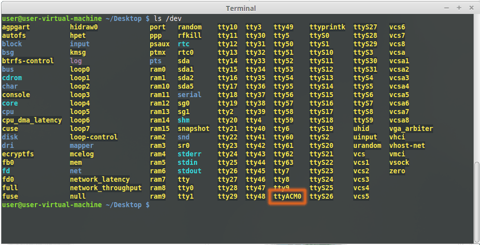
In this particular case, the device shows up as ttyACM0 (highlighted in orange color) but it could be ttyACM1 or ttyACM2, etc… depending on the specific system and other connected devices. Once the device is visible under /dev directory, it can be treated just like any other serial device. Commands can be sent to the device using any mechanism that is valid for regular serial ports such as screen command or Serial Terminal Emulation applications. If there is more than one device connected to the same host computer, each device will be displayed as separate serial devices with unique names. These separate serial devices can be used to control individual devices attached.
Installing on Mac OSX
Mac OSX is usually shipped with USB CDC driver pre-installed. When connected to a Mac computer, this product should appear as a serial port under /dev directory. Usually, the name of the device will be tty.usbserialportx or tty.usbmodemx or similar. The name may be different depending on the Mac OSX version you have. The image below shows the result of ls /dev/*usb* command on a Mac OSX Yosemite system with a USB GPIO/Relay device attached.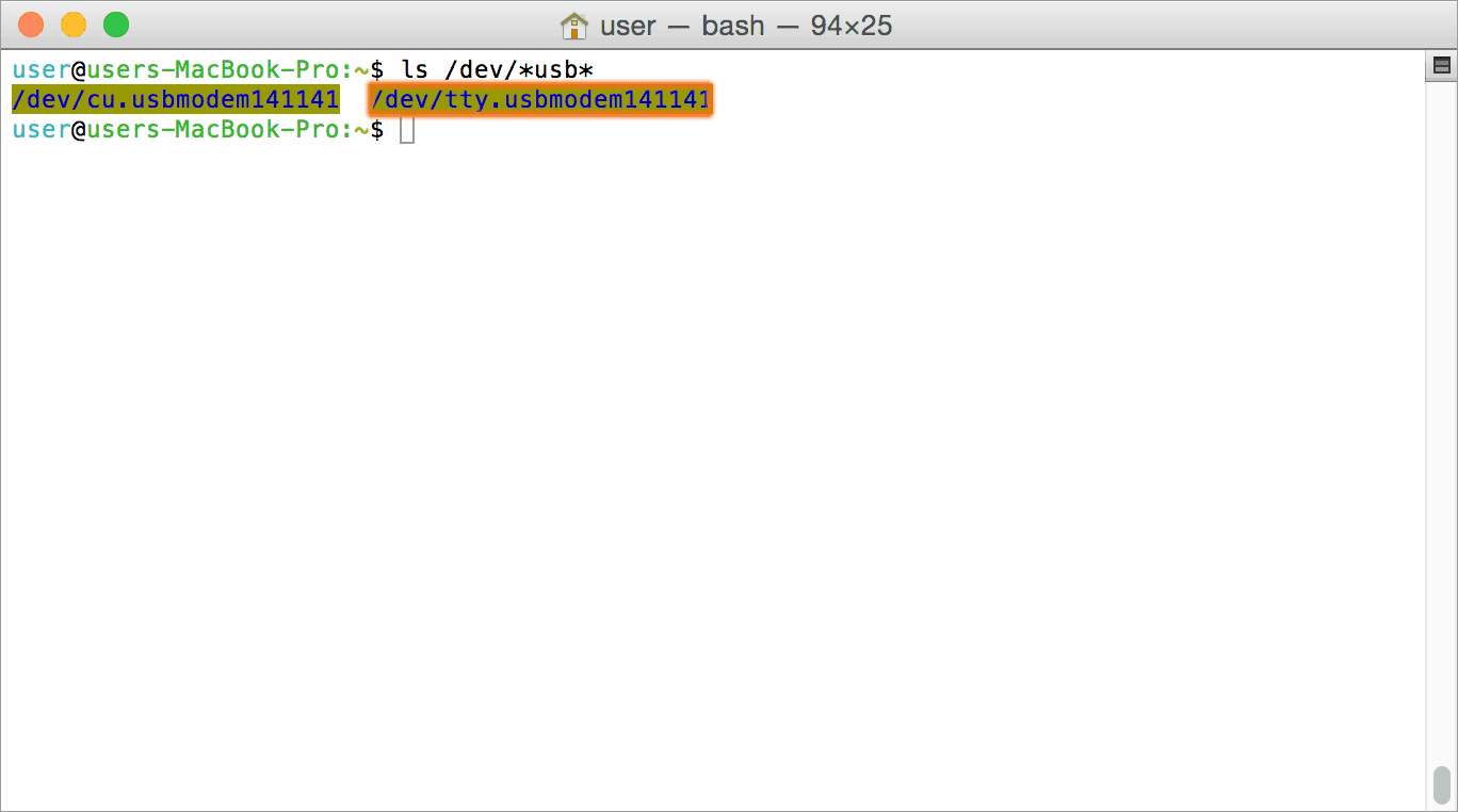
In this particular case, the device shows up as tty.usbmodem141141 (highlighted on orange color) but it could be any name starting tty.usbmodem or even a completely different name depending on the exact version of operating system and other connected devices. Once the device is visible under /dev directory, it can be treated just like any other serial device. If there is more than one device connected to the same host computer, each device will be displayed as separate serial devices with unique names. These separate serial devices can be used to control individual devices attached.
The Modbus Interface
Prodigy ZRX series Modbus Relay Modules use the Modbus protocol for its primary interface. Modbus is a simple yet powerful industry-standard protocol that was originally developed by Modicon systems for transmitting/receiving information over serial links. Prodigy devices use USB/RS485 and TCP/IP as physical interfaces. Since the device uses the USB interface, it represents itself to the operating system as a classic serial device which makes Modbus a very suitable protocol for this product. This also completely hides the complexities of using USB protocol and thus making Prodigy devices as easy to use as a normal serial device.
Modbus Register Map
Coils
Coils are a single bit data type that represents the output state of a single bit entity such as Relay or a GPO. Please note that Coils are always used to represent an output quantity. Writing to a coil will update the output quantity with the value written. Reading a coil will return the data that was previously written. For example, writing “1” to a coil that represents a relay will turn ON the relay and vice versa. Reading from a Coils that represents a turned OFF relay will return value “0”. The Address in the table below shows the position of each coil within the Modbus register map. There are 8 coils corresponding to the 8 GPOs and another set of 16/32/64 coils corresponding to the Relays on ZRX16/ZRX32/ZRX64. The data address of the Coils can be used to access the corresponding Relay or GPO.
| No. | Name | Coil Number | Data Address | Size | Comments |
|---|---|---|---|---|---|
| ZRXxx GPOs | |||||
| 1 | GPO0 | 1 | 0 | 1 | GPO0 ON/OFF |
| 2 | GPO1 | 2 | 1 | 1 | GPO1 ON/OFF |
| 3 | GPO2 | 3 | 2 | 1 | GPO2 ON/OFF |
| 4 | GPO3 | 4 | 3 | 1 | GPO3 ON/OFF |
| 5 | GPO4 | 5 | 4 | 1 | GPO4 ON/OFF |
| 6 | GPO5 | 6 | 5 | 1 | GPO5 ON/OFF |
| 7 | GPO6 | 7 | 6 | 1 | GPO6 ON/OFF |
| 8 | GPO7 | 8 | 7 | 1 | GPO7 ON/OFF |
| ZRXxx Relays | |||||
| 9 | Relay0 | 65 | 64 | 1 | Relay0 ON/OFF |
| 10 | Relay1 | 66 | 65 | 1 | Relay1 ON/OFF |
| 11 | Relay2 | 67 | 66 | 1 | Relay2 ON/OFF |
| - | - | - | - | - | - |
| - | - | - | - | - | - |
| 22 | Relay13 | 78 | 77 | 1 | Relay13 ON/OFF |
| 23 | Relay14 | 79 | 78 | 1 | Relay14 ON/OFF |
| 24 | Relay15 | 80 | 79 | 1 | Relay15 ON/OFF |
| ZRX32/64 Relays Continued | |||||
| 25 | Relay16 | 81 | 80 | 1 | Relay16 ON/OFF |
| 26 | Relay17 | 82 | 81 | 1 | Relay17 ON/OFF |
| 27 | Relay18 | 83 | 82 | 1 | Relay18/ ON/OFF |
| - | - | - | - | - | - |
| - | - | - | - | - | - |
| 38 | Relay29 | 94 | 93 | 1 | Relay29 ON/OFF |
| 39 | Relay30 | 95 | 94 | 1 | Relay30 ON/OFF |
| 40 | Relay31 | 96 | 95 | 1 | Relay31 ON/OFF |
| ZRX64 Relays Continued | |||||
| 41 | Relay32 | 97 | 96 | 1 | Relay32 ON/OFF |
| 42 | Relay33 | 98 | 97 | 1 | Relay33 ON/OFF |
| 43 | Relay34 | 99 | 98 | 1 | Relay34 ON/OFF |
| - | - | - | - | - | - |
| - | - | - | - | - | - |
| - | - | - | - | - | - |
| 68 | Relay60 | 125 | 124 | 1 | Relay60 ON/OFF |
| 69 | Relay61 | 126 | 125 | 1 | Relay61 ON/OFF |
| 70 | Relay62 | 127 | 126 | 1 | Relay62 ON/OFF |
| 71 | Relay63 | 128 | 127 | 1 | Relay63 ON/OFF |
Discrete Inputs
Discrete Inputs are a single bit data type that represents the input state of a single bit entity such as a GPI. For example, by reading the Input bit corresponding to a GPI, the user can get the state of the logic (HIGH/LOW) externally applied to the GPI.
| No. | Name | Input Number | Data Address | Size | Comments |
|---|---|---|---|---|---|
| GPIs | |||||
| 1 | GPI0 | 10001 | 0 | 1 | GPI0 Status High/Low |
| 2 | GPI1 | 10002 | 1 | 1 | GPI1 Status High/Low |
| 3 | GPI2 | 10003 | 2 | 1 | GPI2 Status High/Low |
| 4 | GPI3 | 10004 | 3 | 1 | GPI3 Status High/Low |
| 5 | GPI4 | 10005 | 4 | 1 | GPI4 Status High/Low |
| 6 | GPI5 | 10006 | 5 | 1 | GPI5 Status High/Low |
| 7 | GPI6 | 10007 | 6 | 1 | GPI6 Status High/Low |
| 8 | GPI7 | 10008 | 7 | 1 | GPI7 Status High/Low |
Holding Registers
| No. | Name | Input Number | Data Address | Size | Access | Comments |
|---|---|---|---|---|---|---|
| Relay Related Registers | ||||||
| 1 | Relay Timer Registers | 40001 | 0 | 48 for ZRX16 96 for ZRX32 192 for ZRX64 | WR | 3*16=48 Relay timer registers for 16 relays 3*32 = 96 Relay timer registers for 32 relays 3*64 = 192 Relay timer registers for 64 relays |
| 2 | Relay Fail safe Value Registers | 40257 | 256 | 1 for ZRX16 2 for ZRX32 4 for ZRX64 | WR | Fail Safe value registers for relays. |
| 3 | Relay Power ON value Register | 40261 | 260 | 1 for ZRX16 2 for ZRX32 4 for ZRX64 | WR | Power ON value registers for relays. |
| GPIO Related Registers | ||||||
| 4 | GPO Timer Registers | 40265 | 264 | 24 | WR | 3*8= 24 GPO timer registers for 8 GPOs |
| 5 | GPI Power ON Pullup Value Registers | 40501 | 500 | 1 | WR | Power ON Pull-up value register for GPIs |
| 6 | GPI Fail safe Pullup Value Registers | 40517 | 516 | 1 | WR | Fail Safe Pull-up value register for GPIs |
| 7 | GPI Power ON Pull down Value Registers | 40533 | 532 | 1 | WR | Power ON Pull down value register for GPIs |
| 8 | GPI Fail Safe Pull down Value Registers | 40549 | 548 | 1 | WR | Fail safe Pull down value register for GPIs |
| 9 | GPO Power ON Open drain Value Registers | 40565 | 564 | 1 | WR | Power ON Open drain value register for GPOs |
| 10 | GPO Fail safe Open drain value Registers | 40581 | 580 | 1 | WR | Fail safe Open drain value register for GPOs |
| 11 | GPIO Fail safe Value Registers | 40597 | 596 | 1 | WR | Fail safe value register for GPIOs |
| 12 | GPIO Power ON Value Registers | 40605 | 604 | 1 | WR | Power ON value register for GPIOs |
| Watchdog Configuration Area | ||||||
| 13 | Watchdog Holding Registers | 40613 | 612 | 3 | WR | Watchdog Config, timer, timeout value registers |
| Device Configuration Area | ||||||
| 14 | User ID | 48051 | 8050 | 2 | WR | Two registers (4 bytes) for storing custom user data. |
| 15 | USB Configuration Area | 48101 | 8100 | 2 | WR | Slave ID, protocol config value registers for USB Interface |
| 16 | RS485 Configuration Area | 48165 | 8164 | 2 | WR | Slave ID, Baud rate value registers for RS485 Interface |
| 17 | Ethernet Configuration Area | 48229 | 8228 | 23 | WR & RO | Host name, IP address, MAC etc... for Ethernet Interface |
Input Registers
| No. | Name | Input Number | Data Address | Size | Access | Comments |
|---|---|---|---|---|---|---|
| Device Info Area | ||||||
| 1 | Vendor ID | 38001 | 8000 | 1 | RO | |
| 2 | Product ID | 38002 | 8001 | 1 | RO | |
| 3 | OEM Vendor ID | 38003 | 8002 | 1 | RO | |
| 4 | OEM Product ID | 38004 | 8003 | 1 | RO | |
| 5 | HW major version and Minor version | 38005 | 8004 | 1 | RO | Hardware revision information. |
| 6 | Firmware major, minor version | 38006 | 8005 | 1 | RO | Firmware revision information |
| 7 | Register Map major, minor version | 38009 | 8008 | 1 | RO | Major and Minor versions for Modbus register map |
| ZRXxx Analog Inputs | ||||||
| 8 | ADC0 | 30001 | 0 | 1 | RO | ADC0 Value |
| 9 | ADC1 | 30002 | 1 | 1 | RO | ADC1 Value |
| 10 | ADC2 | 30003 | 2 | 1 | RO | ADC2 Value |
| 11 | ADC3 | 30004 | 3 | 1 | RO | ADC3 Value |
| 12 | ADC4 | 30005 | 4 | 1 | RO | ADC4 Value |
| 13 | ADC5 | 30006 | 5 | 1 | RO | ADC5 Value |
| ZRX16/32 Analog Inputs Continued | ||||||
| 14 | ADC6 | 30007 | 6 | 1 | RO | ADC6 Value |
| 15 | ADC7 | 30008 | 7 | 1 | RO | ADC7 Value |
Register Formats
Let’s look at how to write values to each register.
Holding registers and its format are explained in the table below:-
| No. | Register | Register Format | Comments |
|---|---|---|---|
| Relay Related Registers | |||
| 1 | Relay Timer Value Registers | - 2*16 bit Registers for 32 bit timer value for relays. | Register 1 - Lower Bytes of Timer value. Default Value - 0 Minimum Value to be written - 500h Register 2 - Higher Bytes of Timer Value. Default Value - 0 |
| 2 | Relay Timer Config Register | - 16 bit register - Bit 0 - Enable Timer - Bit 1:2 - Timer Type - Bit 3:4 - Timer Action | Bit 0 :- 0 - Stops Timer 1 - Starts Timer Default Value - 0 ------------------------ Bit 1:2 :- 00 - Single shot Timer 01 - Periodic Timer Default Value - 0 ------------------------ Bit3:4 :- 00 - Relay OFF 01 - Relay ON 10 - Relay Toggle 11 - Reserved Default Value - 0 |
| 3 | Relay Fail Safe Value Register | - 16 bit register for 16 Relays. - Each bit for each relay | Each bit represents relay status. 0 - Relay OFF 1 - Relay ON Default Value - 0 |
| 4 | Relay Power ON Value Register | - 16 bit register for 16 relays - Each bit for each relay | Each bit represents relay status. 0 - Relay OFF 1 - Relay ON Default Value - 0 |
| GPIO Related Registers | |||
| 5 | GPO Timer Value Registers | - 2*16 bit Registers for 32 bit timer value for GPOs. | Register 1 - Lower Bytes of Timer value. Default Value - 0 Minimum Value to be written - 01F4h Register 2 - Higher Bytes of Timer Value. Default Value - 0 |
| 6 | GPO Timer Config Register | - 16 bit register - Bit 0 - Enable Timer - Bit 1:2 - Timer Type - Bit 3:4 - Timer Action | Bit 0 :- 0 - Stops Timer 1 - Starts Timer Default Value - 0 ------------------------ Bit 1:2 :- 00 - Single shot Timer 01 - Periodic Timer Default Value - 0 ------------------------ Bit3:4 :- 00 - GPO OFF 01 - GPO ON 10 - GPO Toggle 11 - Reserved Default Value - 0 |
| 7 | GPI Power ON Pull-Up Value Registers | - 16 bit Register for 16 GPIs - Each bit for each GPI | Each bit to enable/Disable pull-up for the GPIs while power ON. 0 - Pull-Up Disabled 1 - Pull- Up Enabled Default Value - 0 |
| 8 | GPI Power ON Pull-down Value Registers | - 16 bit Register for 16 GPIs - Each bit for each GPI | Each bit to enable/Disable pull-down for the GPIs while Power ON. 0 - Pull-Down Disabled 1 - Pull- Down Enabled Default Value - 0 |
| 9 | GPO Power ON Open Drain Value Register | - 16 bit Register for 16 GPOs - Each bit for each GPO | Each bit to enable/Disable open drain for the GPOs while Power ON. 0 - Open drain Disabled 1 - Open drain Enabled Default Value - 0 |
| 10 | GPI Fail Safe Pull-Up Value Registers | - 16 bit Register for 16 GPIs - Each bit for each GPI | Each bit to enable/Disable pull-down for the GPIs while Fail safe occurs. 0 - Pull-Down Disabled 1 - Pull- Down Enabled Default Value - 0 |
| 11 | GPI Fail Safe Pull-down Value Registers | - 16 bit Register for 16 GPIs - Each bit for each GPI | Each bit to enable/Disable pull-down for the GPIs while Fail safe occurs. 0 - Pull-Down Disabled 1 - Pull- Down Enabled Default Value - 0 |
| 12 | GPO Fail Safe Open Drain Value Register | - 16 bit Register for 16 GPOs - Each bit for each GPO | Each bit to enable/Disable open drain for the GPOs while Fail safe occurs. 0 - Open drain Disabled 1 - Open drain Enabled Default Value - 0 |
| 13 | GPIO Fail Safe Value Registers | - 16 bit Register for 8 GPOs - Bit 0:7 - Each bit for each GPO - Bit 8:15 - Each bit for Input/Output mode of GPIOs | Bit 0:7 :- Each bit represents GPO status. 0 - GPO OFF 1 - GPO ON Default Value - 0 ------------------------ Bit 8:15 :- Each bit represents the Input/Output mode of corresponding GPIOs 0 - Output 1 - Input Default Value - 0 |
| 14 | GPIO Power ON Value Registers | - 16 bit Register for 8 GPOs - Bit 0:7 - Each bit for each GPO - Bit 8:15 - Each bit for Input/Output mode of GPIOs | Bit 0:7 :- Each bit represents GPO status. 0 - GPO OFF 1 - GPO ON Default Value - 0 ------------------------ Bit 8:15 :- Each bit represents the Input/Output mode of corresponding GPIOs 0 - Output 1 - Input Default Value - 0 |
| Watchdog Holding Registers | |||
| 15 | Watchdog config Register | -16 bit register to Enable/Disable watchdog timer - Bit 0 - ON Bit - Bit 1 - Mode Select Bit - Bit 2:15 - Reserved | Bit 0 :- 0 - Disable Watchdog Timer 1 - Enable Watchdog Timer Default Value - 0 ------------------------ Bit 1 :- 0 - Default Mode 1 - Manual Mode(Reserved) Default Value - 0 ------------------------ Bit 2:15 :- XX - Reserved Default Value - 0 |
| 16 | Watchdog timer Value Register | - 16 bit Register for watchdog timer value. | Fail safe occurs when this value reaches the timeout value. Default Value - 0 |
| 17 | Watchdog timeout Value | - 16 bit Register for watchdog timeout value. | Represents at what time the fail safe should occur. Default Value - 0 |
| Common Configuration Holding Registers | |||
| 18 | User ID Holding Register | - 2*16 bit registers for User ID | 4 bytes for User ID. Default Value - 0 |
| USB Configuration Holding Registers | |||
| 19 | Slave ID | - 16 bit register for USB Slave ID | Slave ID can be 1-247. 248-255 - Reserved for special functions Default Value - 1 |
| 20 | Baud Rate | - 16 bit register for USB baud rate | Baud rate can be 9600, 19200, 38400, 57600, 115200 Default Value - 57600 |
| 21 | Protocol Configuration | - 16 bit register for swap between protocols(RTU,JSON,XML) - Bit 0:2 - Config Bit | Bit 0 :- 0 - Disable RTU 1 - Enable RTU Default Value - 1 ------------------------ Bit 1 :- 0 - Disable JSON 1 - Enable JSON Default Value - 0 ------------------------ Bit 2 :- 0 - Disable XML 1 - Enable XML Default Value - 0 |
| RS485 Configuration Holding Registers | |||
| 22 | Slave ID | - 16 bit register for RS485 Slave ID | Slave ID can be 1-247. 248-255 - Reserved for special functions Default Value - 1 |
| 23 | Baud Rate | - 16 bit register for RS485 baud rate | Baud rates - Values ----------- --------- 9600 - 10 or 0x000A 19200 - 11 or 0x000B 38400 - 12 or 0x000C 57600 - 13 or 0x000D 115200 - 14 or 0x000E Default Value - 10 or 0x000A |
| Ethernet Configuration Holding Registers | |||
| 24 | Host Name | - 8*16 bit registers for host name | Host name length is limited to 16 characters |
| 25 | IP address | - 2*16 bit registers for IP Address | IP V4 properties of Ethernet interface. |
| 26 | IP Mask | - 2*16 bit registers for IP Mask | |
| 27 | Default Gateway | - 2*16 bit registers for Default Gateway | |
| 28 | Primary DNS | - 2*16 bit registers for Primary DNS | |
| 29 | Secondary DNS | - 2*16 bit registers for Secondary DNS | |
| 30 | DHCP Enable | -16 bit register for DHCP Enable - Bit 0 - Enable Bit - If enabled, Get IP address automatically, or static IP configuration. - Disable DHCP to write IPV4 properties. | Bit 0 :- 0 - Disable DHCP 1 - Enable DHCP Default Value - 1 ------------------------ Bit 1:15 :- X -Reserved Default Value - 0 |
| 31 | TCP Port | - 16 bit registers for TCP Port | TCP port for Ethernet connection. Default value - 502 |
| 32 | MAC Address | - 3*16 bit Read Only registers for MAC Address | MAC address of Ethernet interface |
★ IP V4 properties of the Ethernet interface will be writable only if the DHCP is disabled.
Similarly, input registers’ format is as follows:-
| No. | Register | Register Format | Comments |
|---|---|---|---|
| 1 | Vendor ID | - 16 bit Register for Vendor ID | Default Value - 0x2A19 |
| 2 | Product ID | - 16 bit Register for Product ID | ZRX64 - 0x2504 or 0x2501 ZRX32 - 0x2505 or 0x2502 ZRX16 - 0x2506 or 0x2503 Default Value - Depends on the Product |
| 3 | OEM Vendor ID | - 16 bit register for OEM Vendor ID | Default Value - 0 |
| 4 | OEM Product ID | - 16 bit register for OEM Product ID | Default Value - 0 |
| 5 | HW major version and Minor version | - 16 bit register for Hardware major and minor version | Hardware revision information. Default Value - 1 |
| 6 | Firmware major, minor version | - 16 bit register for Firmware major and minor version | Firmware revision information. Default Value - 1 |
| 7 | Firmware bugfix/patch level | - 16 bit register for Firmware bugfix/patch level | Firmware bugfix/patch level Default Value - 0 |
| 8 | PNV data format major, minor version | - 16 bit register for PNV data format major, minor version | PNV data format major, minor version Default Value - 1 |
| 9 | Register Map major, minor version | - 16 bit register for Register map major and minor version | Major and Minor versions for Modbus register map Default Value - 1 |
Controlling Prodigy ZRXxx using off the shelf software
Prodigy ZRX devices’ support for Modbus protocol makes it easier to use with virtually any software that supports Modbus. This section of the document demonstrates how to use Prodigy ZRX devices with some of the software that is available in the market.
Windows
qModMaster
QModMaster is free software that emulates Modbus master and can be used to access any device that is Modbus compatible. QModMaster can be downloaded for free at https://sourceforge.net/projects/qmodmaster/. Follow the steps below to see how to use Prodigy ZRX devices with QModMaster using RTU and TCP.
Download and install QModMaster.
To control the device via Modbus RTU, follow the simple steps given below:
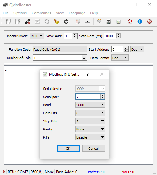
Step 1:
Run QModMaster and select “Modbus RTU” from the Options menu. Enter Serial Port name and other settings as in the image below and click OK. Serial Port name must match the port name assigned to the device by the Operating System.
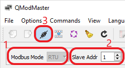
Step 2:
- Select RTU as Modbus mode.
- Select the proper Slave ID of the device.
- Then, click the “Connect” button to connect to the device.
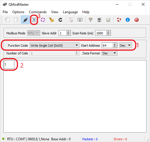
Step 3:
- Select the “Write Single Coil” function code in the Function Code combo box, enter the Data Address of the first Relay (Relay Index 0) in the Start Address box.
- Enter value 1 (corresponds to Relay ON state) in the data cell.
- Now click the Read/Write button to send the new value to the device.
If everything works fine, you will hear the relay clicks and any circuitry connected to the relay will be activated. To read the status of a Relay, the same sequence applies but select the “Read Coils” function code instead.
Similarly, to control the device via Modbus TCP, follow the steps below:
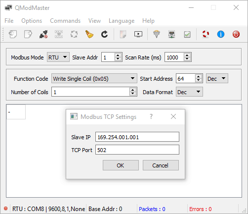
Step 1:
Run QModMaster and select “Modbus TCP” from the Options menu. Enter the IP Address of the device and TCP port number as in the image below and click OK.
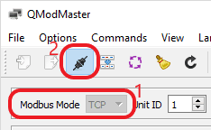
Step 2:
- Select TCP as Modbus mode.
- Then, click the “Connect” button to connect to the device.
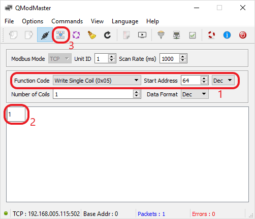
Step 3:
- Select the “Write Single Coil” function code in the Function Code combo box, enter the Data Address of the first Relay (Relay Index 0) in the Start Address box.
- Enter value 1 (corresponds to Relay ON state) in the data cell.
- Now click the Read/Write button to send the new value to the device.
If everything works fine, you will hear the relay clicks and any circuitry connected to the relay will be activated. To read the status of a Relay, the same sequence applies but select the “Read Coils” function code instead.
Additional Information
Using relay modules with inductive loads
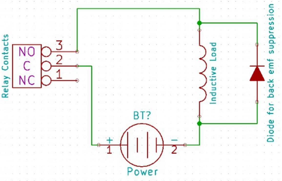
Diode As Snubber
It is important to take additional care when using relays with inductive loads. An inductive load can be pretty much anything that has a coil and works based on magnetic principles like Motors, Solenoids, and transformers. But in practice, even a wire longer than a few feet can display substantial inductance. Inductive loads produce back emf when the magnitude of the load current changes. The back emf can be in the order of tens or even hundreds of voltage (See this Wikipedia article http://en.wikipedia.org/wiki/Counter-electromotive_force). This effect is most severe when power is disconnected from the inductive load because the rate of change of current is maximum at that point. Even though the back emf lives only for a very short time (a few milliseconds) it can cause sparks between the relay contacts and can deteriorate the contact quality over time and reduce the life span for the relays considerably.
So it is important to take countermeasures to suppress the back emf to acceptable levels to protect relay contacts. Usually, this requires connecting electronic devices in parallel with the load such that they absorb the high voltage components generated by the load. For solenoids, connecting a diode (fast switching diode is recommended) in parallel to the load (in reverse direction to the load current) is very effective. A diode used for this purpose is usually called a freewheeling diode. Please see the diagram on the right for connection details.
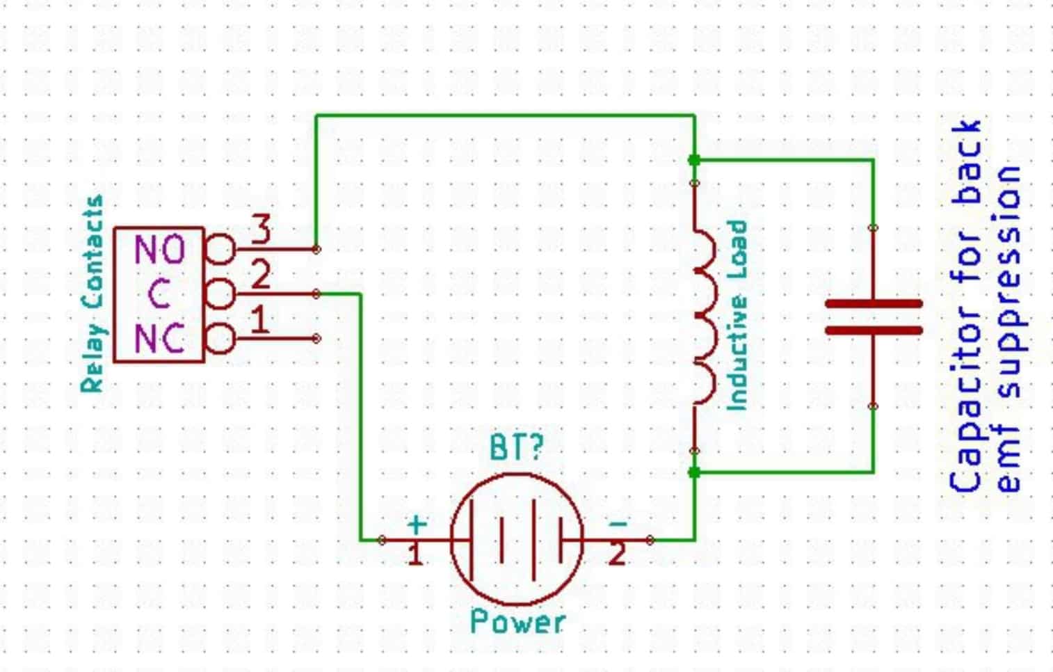
Capacitor As Snubber
A capacitor with a proper rating is recommended for protecting the relay contacts when a motor is used as a load. The capacitor should be rated enough to withstand the back emf that is generated by the motor. Please see the diagram below for connection details.
Please note that the relay modules are NOT shipped with back emf suppression devices pre-installed. The exact kind of suppression device and the parameters of the selected device can vary depending on the load itself. Some of the parameters that affect the suppression device selection are the inductance of the load, power supply voltage, load current, physical size/structure of the load, etc.. It is obvious that it is impossible for us to predict these parameters and design required back emf suppression device and incorporate that on the board. So we believe this is a task best left to the module user. There is an excellent article on designing back emf suppression on Wikipedia at http://en.wikipedia.org/wiki/Flyback_diode
Analog to Digital Converters (ADCs)
Prodigy ZRX devices do support Analog to Digital Conversion on some of the GPIO terminals. A list of GPIOs that supports analog function in this product is listed elsewhere in this document. GPIOs don’t need to be configured especially in order to use them as analog inputs. Simply reading the Analog Input Register corresponding to the IO will automatically put the IO into Analog Input mode and read the analog value. The resolution of the ADC on this product is 12 bits. The input voltage range of the ADC is 0 – 3.3V.
GPIO with Switches
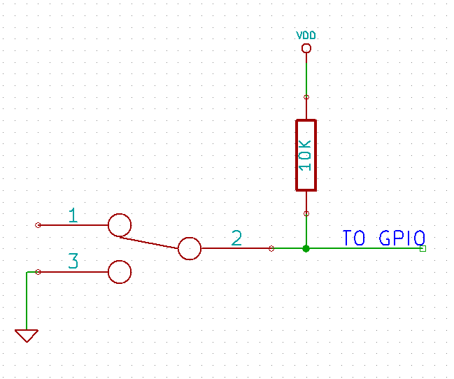 It is possible to read the position of a switch that is connected to a GPIO. An SPST or SPDT switch is recommended to use with GPIOs. Push switches that maintain the contacts closed only for a very short time so using them is discouraged. The fundamental idea of using a switch with GPIO is to have the switch cause a voltage level change at the GPIO pin when pressed. Usually, this is achieved by using an external pull-up resistor along with the switch. The pull up resistor is connected between the GPIO and VDD and the switch is connected between the GPIO and ground. When the switch is not pressed, the pull-up resistor will cause the GPIO to stay at the VDD voltage level. When the switch is pressed, the GPIO is short-circuited to the ground and stays at zero voltage. This change in voltage and thus the position of the switch can be read by simply reading the Discrete Input bit corresponding to the GPIO.
Technical Specifications
| Parameter | Value | Unit |
|---|---|---|
| Number of relays | 16/32/64 | |
| Number of GPIOs | 8 | |
| Number of analog inputs (Multiplexed with GPIOs) | 8/8/6 | |
| Power supply voltage (External) | 12 | V |
| IO Specifications | ||
| Maximum IO source current – ZRX16/ZRX32 : IO0, IO7 | 15 | mA |
| Maximum IO source current – ZRX16/ZRX32 : IO1 – IO6 | 25 | mA |
| Maximum IO source current – ZRX64 : IO0 | 15 | mA |
| Maximum IO source current – ZRX64 : IO1 – IO7 | 25 | mA |
| Maximum IO sink current – ZRX16/ZRX32 : IO0, IO7 | 15 | mA |
| Maximum IO sink current – ZRX16/ZRX32 : IO1 – IO6 | 25 | mA |
| Maximum IO sink current – ZRX64 : IO0 | 15 | mA |
| Maximum IO sink current – ZRX64 : IO1 – IO7 | 25 | mA |
| GPIO input low voltage | 0.8 | V |
| GPIO input high voltage | 2 | V |
| GPIO output low voltage | 0 | V |
| GPIO output high voltage | 3.3 | V |
| ADC Specifications | ||
| Resolution | 12 | bits |
| Full scale range | 0 – 3.3 | V |
| Reference voltage | 3.3 | V |
| Relay Specifications | ||
| Nominal relay coil voltage | 12 | V |
| Nominal coil power consumption (per relay) | 120 | mW |
| Relay contact material | Silver Alloy | |
| Contact rating | 5A/ 250V AC 5A/ 30V DC | |
| Maximum switching voltage | 245VAC/ 30VDC | |
| Maximum switching current | 5 | A |
| Maximum switching power | 250VA/ 150W | |
| Contact resistance (initial) | 100 | mΩ |
| Insulation resistance | 1000 | MΩ |
| Life expectancy (Electrical) | 50,000 | Operations (5A 250VAC/24VDC, Resistive load) |
| Life expectancy (Mechanical) | 20000000 | Operations |
| Maximum switching on response time | 10 | mS |
| Maximum switching off response time | 5 | mS |
| Shock resistance (Functional) | 98 | m/s2 |
| Shock resistance (Destructive) | 980 | m/s2 |
| Vibration resistance | 10Hz to 55Hz 1.5mm DA | |
| Other Information | ||
| USB Vendor ID | 0x2A19 | |
| USB Product ID | ZRX64 - 0x2501 ZRX32 - 0x2502 ZRX16 - 0x2503 | |
Frequently Asked Questions (FAQs)
Q. What are the serial parameters I need to use when communicating with this board?
A. Since this module uses USB as the underlying transport mechanism, most of the serial parameters do not affect the communication. You can leave all parameters to any legal value (Eg: 2400, 4800, 9600, etc… for baud rate) except Flow control. Flow control needs to be set to “None”.
Q. Where do I find the driver for this product?
A. Visit http://numato.com and navigate to the product page. There will be a link to download windows driver. Linux does not require driver installation since in most cases they are shipped with the driver pre-installed.
Q. Why there is no .sys or .exe file in the Windows driver package I downloaded?
A. This product uses the USB CDC driver binary which is already present on Windows. All Windows versions (with the exception of Embedded Editions) has this driver binary installed by default. The .inf and .cat files present in the zip file helps Windows identify the device properly and associate the appropriate driver (.sys) to the device
Q. Does this product work with Linux?
A. Yes, this product works with Linux. Please see more details on how to use this product with Linux elsewhere in this document.
Q. Does this product work with Mac OSX?
A. Yes, this product works with Mac OSX. Please see more details on how to use this product with Mac elsewhere in this document.
Q. What is the software that this product work with?
A. This product works with almost any software that has support for standard Modbus. Some examples can be found elsewhere in this document. Different software is written by different developers with different purposes in mind. So you may encounter some software that may not work with this product. But usually, alternatives are available in most if not all cases.
Q. I’m using x language for programming. How do I find out if this language can be used to program and control the GPIO module?
A. Find out if the language of interest supports some kind of APIs/Functions/Components for serial communication. If it does, most likely you should be able to use that language with this module. It may also be possible to find libraries such as libModbus that offers high-level APIs. Using such libraries can speed up development quite a bit.
Q. I need a customized version of this product, can Numato Lab do the customization for me?
A. Yes, we can definitely do customization but there may be minimum order requirements depending on the level of customization required. Please write to help@numato.com for a quote.
Q. Where can I buy this product?
A. All Numato products can be ordered directly from our web store http://www.numato.com. We accept major credit cards and Paypal and ship to almost all countries with a few exceptions. We do have distributors in many countries where you can place your order. Please find the current list of distributors at http://numato.com/distrib.