Introduction
| SL No. | SKU | Description | Operating temperature |
|---|---|---|---|
| 1. | NLFMPSA001-B | EagleCore C02 | -40°C to 85°C |
The EagleCore C02 carrier is equipped with 3xQ-pair differential mezzanine connectors, enabling compatibility with various AMD System-on-Module (SoM) solutions such as the EagleCore ZU-Plus MPSoC SoM. The carrier introduces FPIC (FPGA Peripheral Interface Connector), a new I/O expansion interface developed by Numato Lab, designed to provide flexible and scalable peripheral connectivity. The board includes a single FPIC interface, where the FPIC standard connector is intended for general-purpose peripheral expansion.
The carrier board integrates a comprehensive set of onboard features to enhance flexibility and ease of use. These include a PCIe x4 connector for high-speed expansion, an SD card slot for data and program storage, and an RJ45 Ethernet interface for network connectivity. The board also provides FMC HPC support for high-speed I/O and advanced expansion capabilities. Additional interfaces include a fan header for thermal management, USB OTG support, two CAN headers, an IO header, and SMA connectors. The board also features a USB Type-C connector for UART communication and USB-based programming, along with a dedicated JTAG header for debugging and development.
Board Features
- Three Q-pair differential mezzanine connectors for high-speed SoM interfacing
- FTDI FT2232H for FPGA-to-host communication
- RJ45 Ethernet jack for network connectivity
- USB Type-C connector for UART communication and programming
- USB Micro-AB connector with OTG support
- PCIe x4 male header for high-speed expansion and peripheral connectivity
- 12V DC power input
- 12V fan header for thermal management
- AMD-compatible JTAG header for programming and debugging
- 2×6 IO Expansion Header.
- FPIC ST connector for user-defined peripheral expansion
- FMC connector supporting up to 154 user I/O’s
- FMC HPC connector with support for up to 4 SERDES lanes
- Two CAN interface headers for automotive and industrial communication
- Three SMA connectors for supplying external reference clocks to GT transceiver banks, enabling flexible clocking based on peripheral requirements
How to use EagleCore C02
The following sections describe how to use this module in detail.
Hardware Accessories Required
In addition to the module, you may require the accessories listed below for a convenient and expedited installation:
- 12 V DC Power Supply.
- USB Type-C Cable.
- AMD Platform Cable USB II compatible JTAG programmer (Optional).
- EagleCore SoM module.
Wiring Diagram
 Note: The MicroSD Card slot and RTC Coin cell battery are kept below the carrier.
DC Power Supply
The EagleCore SOM Carrier is configured to use power from the DC power supply by connecting it to the
External DC Jack (J1). The external power supply should be in the range of +12V 5A.
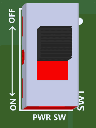
Power Switch
The Power Switch (SW1)is used to switch on/off the board. Sliding it to ON to supply power from the External DC Jack to the board. Sliding it to OFF to power off the board
.
Power LED
The EagleCore SOM Carrier has a power LED (PWR) that will illuminates red colour when the board receives sufficient power during startup.
Reset
The EagleCore C02 includes a push-button switch (DEV RST) for system reset functionality, connected to the FPGA’s system reset pin. Pressing this button resets the entire device, including the processing system and programmable logic, bringing the system back to a known initial state. This is useful during development for recovering from unexpected states or restarting applications without cycling the power.

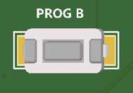
PROGB
The EagleCore C02 includes a dedicated switch (PROG B) for PROG_B functionality, which is connected to the corresponding PROG_B pin on the FPGA. Driving PROG_B low forces the FPGA to reset and clear its current configuration, after which it automatically re-initiates the configuration process when released high.
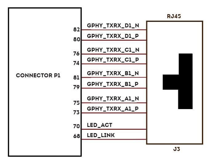
Gigabit Ethernet Port
The EagleCore C02 supports 1 Gigabit ethernet communication lanes (J3)which support 10/100/1000Mbps Ethernet interface. The Ethernet LINK LED(Green) indicates the presence of a network connection when illuminated, while the Gigabit Ethernet ACTIVITY LED(Orange) signals active data transmission or reception over the network.
USB Interface
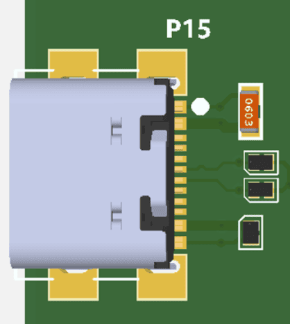
The onboard USB connector (P15) helps a PC/Linux/Mac computer to communicate with this module.
Use a USB type C cable to connect with a PC. This port will act as both JTAG and UART interface.
USB 2.0 OTG Connector
The EagleCore C02 provides a USB 2.0 OTG interface (P8) and can be accessed using a Micro-B connector. USB OTG supports both Host, Device, and OTG modes based on the configuration made in the USB ID pin. An LED (USB_5V) is connected with the USB_5V as an indication of the presence of the VBUS in the USB pin.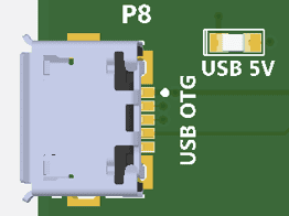
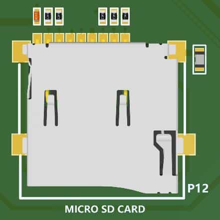
MicroSD Card
The EagleCore C02 supports a microSD card slot (P12), offering additional non-volatile memory storage capacity. It offers a compact and removable storage solution, making it ideal for storing data that exceeds the internal memory capacity of the FPGA. FPGAs can use microSD cards to store boot images or configuration data, which are loaded into the FPGA at startup.
Mode Selection DIP Switches
EagleCore C02 has DIP switches (SW8) for changing the boot configuration of the FPGA based on the required functionality. Users can utilize all four pins or only the necessary ones, leaving the remaining MODE pins unconnected.
EagleCore ZU-Plus SOM
The boot configuration of the EagleCore ZU-Plus SOM will be based on the below configuration of switches: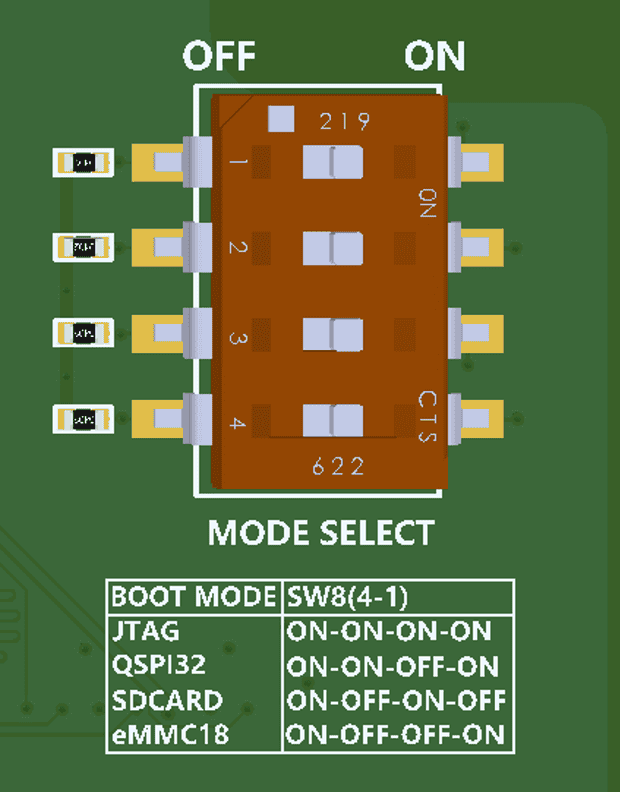
| MODE3 | MODE2 | MODE1 | MODE0 | |
|---|---|---|---|---|
| JTAG | 0 | 0 | 0 | 0 |
| QSPI (32Bit) | 0 | 0 | 1 | 0 |
| SD Card(2.0) | 0 | 1 | 0 | 1 |
| EMMC (1.8V) | 0 | 1 | 1 | 0 |
RTC Coin Cell Holder
The EagleCore C02 has a Coin Cell Holder (BT1) to support 1.8V coin cell that will support 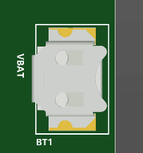
backup voltage for RTC when main power supply is off. RTC maintains accurate timekeeping through these battery-backup. The battery should be kept in the carrier board for providing voltage if the main power is off.
CAN Header
The EagleCore C02 has 2 CAN (P14)headers dedicated for CAN communication interfaces.
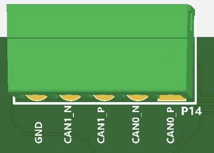
| Pin No. | Signal Name | Function |
|---|---|---|
| 1 | CANH | CAN0_P |
| 2 | CANL | CAN0_N |
| 3 | CANH | CAN1_P |
| 4 | CANL | CAN1_N |
| 5 | GND | GND |
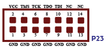
JTAG Header
EagleCore SOM Carrier supports standard JTAG (7×2) Header (P23) for programming and debugging purposes.
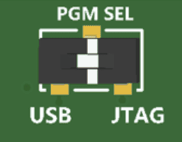
PGM_SEL switch
The EagleCore C02 supports both JTAG and USB-Programming (via FTDI) for AMD FPGA devices. The programming mode can be selected using the PGM_SEL switch . By default, PGM_SEL is set to the OFF position, enabling USB-Programming (via FTDI). Switching PGM_SEL to the ON position configures the board for JTAG programming.
IO Header
| Connector Pin No. | Pin Name | SoM connector Pin No. (Connector name) | SoM connector Pin Name | Connector Pin No. | Pin Name | SoM connector Pin No. (Connector name) | SoM connector Pin Name |
|---|---|---|---|---|---|---|---|
| 1 | IO_1 | 101 (P1) | IO0_P | 7 | IO_2 | 103 (P1) | IO0_N |
| 2 | IO_3 | 105 (P1) | IO2_P | 8 | IO_4 | 107 (P1) | IO2_N |
| 3 | IO_5 | 106 (P1) | IO3_P | 9 | IO_6 | 108 (P1) | IO3_N |
| 4 | IO_7 | 102 (P1) | IO1_P | 10 | IO_8 | 104 (P1) | IO1_N |
| 5 | GND | 11 | GND | ||||
| 6 | VDD1V8 | 12 | VDD1V8 |
XADC (On-chip analog-to-digital converter)
The EagleCore C02 have dedicated header (P17) for differential analog input.

SMA Connectors
The EagleCore c02 supports 3 SMA connectors for differential transceiver clocks. Users can utilize this connector to meet additional transceiver clock requirements.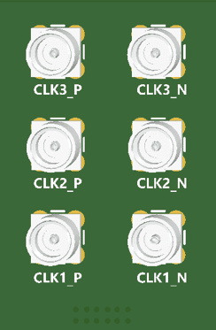
| Connector Pin No. (P1) | Connector Pin Name | Signal Name |
|---|---|---|
| 8 | CLK1_P | CLK_01_P |
| 10 | CLK1_N | CLK_01_N |
| 37 | CLK2_P | CLK_02_P |
| 39 | CLK2_N | CLK_02_N |
| 38 | CLK3_P | CLK_03_P |
| 40 | CLK3_N | CLK_03_N |
FPIC ST Connector
| Pin No. On The Header | Pin Name | Signal name | SoM connector Pin No. (Connector name) | SoM connector Pin Name | Pin No. On The Header | Pin Name | Signal name | SoM connector Pin No. (Connector name) | SoM connector Pin Name |
|---|---|---|---|---|---|---|---|---|---|
| 1 | 5V | 5P0 | 2 | PG_M2C | PG_M2C_FPIC | 42 (P3) | IO11_P | ||
| 3 | GND | GND | 4 | GND | GND | ||||
| 5 | IO1_P/CLK1_P | FPICA_IO1_CC_P | 57 (P3) | IO16_P | 6 | IO0_P/CLK0_P | FPICA_IO0_CC_P | 58 (P3) | IO17_P |
| 7 | IO1_N/CLK1_N | FPICA_IO1_CC_N | 59 (P3) | IO16_N | 8 | IO0_N/CLK0_N | FPICA_IO0_CC_N | 60 (P3) | IO17_N |
| 9 | IO3_P | FPICA_IO3_P | 61 (P3) | IO18_P | 10 | IO2_P | FPICA_IO2_P | 62 (P3) | IO19_P |
| 11 | IO3_N | FPICA_IO3_N | 63 (P3) | IO18_N | 12 | IO2_N | FPICA_IO2_N | 64 (P3) | IO19_N |
| 13 | GND | GND | 14 | GND | GND | ||||
| 15 | IO5_P | FPICA_IO5_P | 47 (P3) | IO12_P | 16 | IO4_P | FPICA_IO4_P | 48 (P3) | IO13_P |
| 17 | IO5_N | FPICA_IO5_N | 49 (P3) | IO12_N | 18 | IO4_N | FPICA_IO4_N | 50 (P3) | IO13_N |
| 19 | IO7_P | FPICA_IO7_P | 51 (P3) | IO14_P | 20 | IO6_P | FPICA_IO6_P | 52 (P3) | IO15_P |
| 21 | IO7_N | FPICA_IO7_N | 53 (P3) | IO14_N | 22 | IO6_N | FPICA_IO6_N | 54 (P3) | IO15_N |
| 23 | GND | GND | 24 | GND | GND | ||||
| 25 | IO9_P/CLK3_P | FPICA_IO9_CC_P | 67 (P3) | IO20_P | 26 | IO8_P/CLK2_P | FPICA_IO8_P | 68 (P3) | IO21_P |
| 27 | IO9_N/CLK3_N | FPICA_IO9_CC_N | 69 (P3) | IO20_N | 28 | IO8_N/CLK2_N | FPICA_IO8_N | 70 (P3) | IO21_N |
| 29 | IO11_P | FPICA_IO11_P | 71 (P3) | IO22_P | 30 | IO10_P | FPICA_IO10_P | 72 (P3) | IO23_P |
| 31 | IO11_N | FPICA_IO11_N | 73 (P3) | IO22_N | 32 | IO10_N | FPICA_IO10_N | 74 (P3) | IO23_N |
| 33 | GND | GND | 34 | GND | GND | ||||
| 35 | IO13_P/CLK5_P | FPICA_IO13_CC_P | 111 (P1) | 36 | IO12_P/CLK4_P | FPICA_IO12_CC_P | 112 (P1) | IO5_P | |
| 37 | IO13_N/CLK5_N | FPICA_IO13_CC_N | 113 (P1) | 38 | IO12_N/CLK4_N | FPICA_IO12_CC_N | 114 (P1) | IO5_N | |
| 39 | IO15_P | FPICA_IO15_P | 115 (P1) | 40 | IO14_P | FPICA_IO14_P | 116 (P1) | IO7_P | |
| 41 | IO15_N | FPICA_IO15_N | 117 (P1) | 42 | IO14_N | FPICA_IO14_N | 118 (P1) | IO7_N | |
| 43 | GND | GND | 44 | GND | |||||
| 45 | IO17_P | 46 | IO16_P | ||||||
| 47 | IO17_N | 48 | IO16_N | ||||||
| 49 | IO19_P | 50 | IO18_P | ||||||
| 51 | IO19_N | 52 | IO18_N | ||||||
| 53 | GND | GND | 54 | GND | |||||
| 55 | IO21_P/CLK7_P | 56 | IO20_P/CLK6_P | ||||||
| 57 | IO21_N/CLK7_N | 58 | IO20_N/CLK6_N | ||||||
| 59 | IO23_P | 60 | IO22_P | ||||||
| 61 | IO23_N | 62 | IO22_N | ||||||
| 63 | GND | GND | 64 | GND | |||||
| 65 | RES | 66 | RES | ||||||
| 67 | RES | 68 | RES | ||||||
| 69 | GA0 | GND | 70 | GA1 | GND | ||||
| 71 | VADJ1 | VDD3V3 | 72 | SCL | SCL_FPIC | 78 (P3) | IO25_P | ||
| 73 | VADJ2 | VDD3V3 | 74 | SDA | SDA_FPIC | 80 (P3) | IO25_N | ||
| 75 | GND | GND | 76 | GND | GND | ||||
| 77 | 3.3V | VDD3V3 | 78 | 3.3V | VDD3V3 | ||||
| 79 | 3.3V | VDD3V3 | 80 | 3.3V | VDD3V3 | ||||
| G5 | GND | GND | G1 | GND | GND | ||||
| G6 | GND | GND | G2 | GND | GND | ||||
| G7 | GND | GND | G3 | GND | GND | ||||
| G8 | GND | GND | G4 | GND | GND |
FMC HPC Header
FMC BANKS A TO E
| A | FMC Pin Name | SoM connector Pin No. (Connector name) | SoM connector Pin Name | B | FMC Pin Name | C | FMC Pin Name | SoM connector Pin No. (Connector name) | SoM connector Pin Name | D | FMC Pin Name | SoM connector Pin No. (Connector name) | SoM connector Pin Name | E | FMC Pin Name | SoM connector Pin No. (Connector name) | SoM connector Pin Name |
|---|---|---|---|---|---|---|---|---|---|---|---|---|---|---|---|---|---|
| A1 | GND | B1 | GND | C1 | GND | D1 | PG_C2M | E1 | GND | ||||||||
| A2 | FMC_DP1_M2C_P | 49 (P1) | RX5_P | B2 | GND | C2 | FMC_DP0_C2M_P | 44 (P1) | TX4_P | D2 | GND | E2 | FMC_HA01_CC_P | 72 (P2) | IO23_P | ||
| A3 | FMC_DP1_M2C_N | 51 (P1) | RX5_N | B3 | GND | C3 | FMC_DP0_C2M_N | 46 (P1) | TX4_N | D3 | GND | E3 | FMC_HA01_CC_N | 74 (P2) | IO23_N | ||
| A4 | GND | B4 | NC | C4 | GND | D4 | FMC_GBTCLK0_M2C_P | 67 (P1) | CLK4_P | E4 | GND | ||||||
| A5 | GND | B5 | NC | C5 | GND | D5 | FMC_GBTCLK0_M2C_N | 69 (P1) | CLK4_N | E5 | GND | ||||||
| A6 | FMC_DP2_M2C_P | 55 (P1) | RX6_P | B6 | GND | C6 | FMC_DP0_M2C_P | 43 (P1) | RX4_P | D6 | GND | E6 | FMC_HA05_P | 82 (P2) | IO27_P | ||
| A7 | FMC_DP2_M2C_N | 57 (P1) | RX6_N | B7 | GND | C7 | FMC_DP0_M2C_N | 45 (P1) | RX4_N | D7 | GND | E7 | FMC_HA05_N | 84 (P2) | IO27_N | ||
| A8 | GND | B8 | NC | C8 | GND | D8 | FMC_LA01_CC_P | 18 (P2) | IO1_P | E8 | GND | ||||||
| A9 | GND | B9 | NC | C9 | GND | D9 | FMC_LA01_CC_N | 20 (P2) | IO1_N | E9 | FMC_HA09_P | 92 (P2) | IO31_P | ||||
| A10 | FMC_DP3_M2C_P | 61 (P1) | RX7_P | B10 | GND | C10 | FMC_LA06_P | 31 (P2) | IO6_P | D10 | GND | E10 | FMC_HA09_N | 94 (P2) | IO31_N | ||
| A11 | FMC_DP3_M2C_N | 63 (P1) | RX7_N | B11 | GND | C11 | FMC_LA06_N | 33 (P2) | IO6_N | D11 | FMC_LA05_P | 28 (P2) | IO5_P | E11 | GND | ||
| A12 | GND | B12 | NC | C12 | GND | D12 | FMC_LA05_N | 30 (P2) | IO5_N | E12 | FMC_HA13_P | 102 (P2) | IO35_P | ||||
| A13 | GND | B13 | NC | C13 | GND | D13 | GND | E13 | FMC_HA13_N | 104 (P2) | IO35_N | ||||||
| A14 | NC | B14 | GND | C14 | FMC_LA10_P | 41 (P2) | IO10_P | D14 | FMC_LA09_P | 38 (P2) | IO9_P | E14 | GND | ||||
| A15 | NC | B15 | GND | C15 | FMC_LA10_N | 43 (P2) | IO10_N | D15 | FMC_LA09_N | 40 (P2) | IO9_N | E15 | FMC_HA16_P | 81 (P3) | IO26_P | ||
| A16 | GND | B16 | NC | C16 | GND | D16 | GND | E16 | FMC_HA16_N | 83 (P3) | IO26_N | ||||||
| A17 | GND | B17 | NC | C17 | GND | D17 | FMC_LA13_P | 48 (P2) | IO13_P | E17 | GND | ||||||
| A18 | NC | B18 | GND | C18 | FMC_LA14_P | 51 (P2) | IO14_P | D18 | FMC_LA13_N | 50 (P2) | IO13_N | E18 | FMC_HA20_P | 91 (P3) | IO30_P | ||
| A19 | NC | B19 | GND | C19 | FMC_LA14_N | 53 (P2) | IO14_N | D19 | GND | E19 | FMC_HA20_N | 93 (P3) | IO30_N | ||||
| A20 | GND | B20 | NC | C20 | GND | D20 | FMC_LA17_CC_P | 58 (P2) | IO17_P | E20 | GND | ||||||
| A21 | GND | B21 | NC | C21 | GND | D21 | FMC_LA17_CC_N | 60 (P2) | IO17_N | E21 | NC | ||||||
| A22 | FMC_DP1_C2M_P | 50 (P1) | TX5_P | B22 | GND | C22 | FMC_LA18_P | 61 (P2) | IO18_P | D22 | GND | E22 | NC | ||||
| A23 | FMC_DP1_C2M_N | 52 (P1) | TX5_N | B23 | GND | C23 | FMC_LA18_N | 63 (P2) | IO18_N | D23 | FMC_LA23_P | 18 (P3) | IO1_P | E23 | GND | ||
| A24 | GND | B24 | NC | C24 | GND | D24 | FMC_LA23_N | 20 (P3) | IO1_N | E24 | NC | ||||||
| A25 | GND | B25 | NC | C25 | GND | D25 | GND | E25 | NC | ||||||||
| A26 | FMC_DP2_C2M_P | 56 (P1) | TX6_P | B26 | GND | C26 | FMC_LA27_P | 28 (P3) | IO5_P | D26 | FMC_LA26_P | 21 (P3) | IO2_P | E26 | GND | ||
| A27 | FMC_DP2_C2M_N | 58 (P1) | TX6_N | B27 | GND | C27 | FMC_LA27_N | 30 (P3) | IO5_N | D27 | FMC_LA26_N | 23 (P3) | IO2_N | E27 | NC | ||
| A28 | GND | B28 | NC | C28 | GND | D28 | GND | E28 | NC | ||||||||
| A29 | GND | B29 | NC | C29 | GND | D29 | NC | E29 | GND | ||||||||
| A30 | FMC_DP3_C2M_P | 62 (P1) | TX7_P | B30 | GND | C30 | SCL_FMC | 77 (P3) | IO24_P | D30 | NC | E30 | NC | ||||
| A31 | FMC_DP3_C2M_N | 64 (P1) | TX7_N | B31 | GND | C31 | SDA_FMC | 79 (P3) | IO24_N | D31 | NC | E31 | NC | ||||
| A32 | GND | B32 | NC | C32 | GND | D32 | 3V3AUX | E32 | GND | ||||||||
| A33 | GND | B33 | NC | C33 | GND | D33 | NC | E33 | NC | ||||||||
| A34 | NC | B34 | GND | C34 | GND | D34 | NC | E34 | NC | ||||||||
| A35 | NC | B35 | GND | C35 | P12V0 | D35 | P3V3 | E35 | GND | ||||||||
| A36 | GND | B36 | NC | C36 | GND | D36 | P3V3 | E36 | NC | ||||||||
| A37 | GND | B37 | NC | C37 | P12V0 | D37 | GND | E37 | NC | ||||||||
| A38 | NC | B38 | GND | C38 | GND | D38 | P3V3 | E38 | GND | ||||||||
| A39 | NC | B39 | GND | C39 | P3V3 | D39 | GND | E39 | VADJ | ||||||||
| A40 | GND | B40 | NC | C40 | GND | D40 | P3V3 | E40 | GND |
FMC BANKS F TO K
| F | FMC Pin Name | SoM connector Pin No. (Connector name) | SoM connector Pin Name | G | FMC Pin Name | SoM connector Pin No. (Connector name) | SoM connector Pin Name | H | FMC Pin Name | SoM connector Pin No. (Connector name) | SoM connector Pin Name | J | FMC Pin Name | SoM connector Pin No. (Connector name) | SoM connector Pin Name | K | FMC Pin Name | SoM connector Pin No. (Connector name) | SoM connector Pin Name |
|---|---|---|---|---|---|---|---|---|---|---|---|---|---|---|---|---|---|---|---|
| F1 | PG_M2C | G1 | GND | H1 | NC | J1 | GND | K1 | NC | ||||||||||
| F2 | GND | G2 | NC | H2 | PRSNT_M2C_L | 98 (P1) | PRSNT_L | J2 | NC | K2 | GND | ||||||||
| F3 | GND | G3 | NC | H3 | GND | J3 | NC | K3 | GND | ||||||||||
| F4 | FMC_HA00_CC_P | 77 (P2) | IO24_P | G4 | GND | H4 | NC | J4 | GND | K4 | NC | ||||||||
| F5 | FMC_HA00_CC_N | 79 (P2) | IO24_N | G5 | GND | H5 | NC | J5 | GND | K5 | NC | ||||||||
| F6 | GND | G6 | FMC_LA00_CC_P | 17 (P2) | IO0_P | H6 | GND | J6 | FMC_HA03_P | 78 (P2) | IO25_P | K6 | GND | ||||||
| F7 | FMC_HA04_P | 87 (P2) | IO28_P | G7 | FMC_LA00_CC_N | 19 (P2) | IO0_N | H7 | FMC_LA02_P | 21 (P2) | IO2_P | J7 | FMC_HA03_N | 80 (P2) | IO25_N | K7 | FMC_HA02_P | 81 (P2) | IO26_P |
| F8 | FMC_HA04_N | 89 (P2) | IO28_N | G8 | GND | H8 | FMC_LA02_N | 23 (P2) | IO2_N | J8 | GND | K8 | FMC_HA02_N | 83 (P2) | IO26_N | ||||
| F9 | GND | G9 | FMC_LA03_P | 22 (P2) | IO3_P | H9 | GND | J9 | FMC_HA07_P | 88 (P2) | IO29_P | K9 | GND | ||||||
| F10 | FMC_HA08_P | 97 (P2) | IO32_P | G10 | FMC_LA03_N | 24 (P2) | IO3_N | H10 | FMC_LA04_P | 27 (P2) | IO4_P | J10 | FMC_HA07_N | 90 (P2) | IO29_N | K10 | FMC_HA06_P | 91 (P2) | IO30_P |
| F11 | FMC_HA08_N | 99 (P2) | IO32_N | G11 | GND | H11 | FMC_LA04_N | 29 (P2) | IO4_N | J11 | GND | K11 | FMC_HA06_N | 93 (P2) | IO30_N | ||||
| F12 | GND | G12 | FMC_LA08_P | 37 (P2) | IO8_P | H12 | GND | J12 | FMC_HA11_P | 98 (P2) | IO33_P | K12 | GND | ||||||
| F13 | FMC_HA12_P | 107 (P2) | IO36_P | G13 | FMC_LA08_N | 39 (P2) | IO8_N | H13 | FMC_LA07_P | 32 (P2) | IO7_P | J13 | FMC_HA11_N | 100 (P2) | IO33_N | K13 | FMC_HA10_P | 101 (P2) | IO34_P |
| F14 | FMC_HA12_N | 109 (P2) | IO36_N | G14 | GND | H14 | FMC_LA07_N | 34 (P2) | IO7_N | J14 | GND | K14 | FMC_HA10_N | 103 (P2) | IO34_N | ||||
| F15 | GND | G15 | FMC_LA12_P | 47 (P2) | IO12_P | H15 | GND | J15 | FMC_HA14_P | 108 (P2) | IO37_P | K15 | GND | ||||||
| F16 | FMC_HA15_P | 82 (P3) | IO27_P | G16 | FMC_LA12_N | 49 (P2) | IO12_N | H16 | FMC_LA11_P | 42 (P2) | IO11_P | J16 | FMC_HA14_N | 110 (P2) | IO37_N | K16 | FMC_HA17_CC_P | 88 (P3) | IO29_P |
| F17 | FMC_HA15_N | 84 (P3) | IO27_N | G17 | GND | H17 | FMC_LA11_N | 44 (P2) | IO11_N | J17 | GND | K17 | FMC_HA17_CC_N | 90 (P3) | IO29_N | ||||
| F18 | GND | G18 | FMC_LA16_P | 57 (P2) | IO16_P | H18 | GND | J18 | FMC_HA18_P | 87 (P3) | IO28_P | K18 | GND | ||||||
| F19 | FMC_HA19_P | 92 (P3) | IO31_P | G19 | FMC_LA16_N | 59 (P2) | IO16_N | H19 | FMC_LA15_P | 52 (P2) | IO15_P | J19 | FMC_HA18_N | 89 (P3) | IO28_N | K19 | FMC_HA21_P | 98 (P3) | IO33_P |
| F20 | FMC_HA19_N | 94 (P3) | IO31_N | G20 | GND | H20 | FMC_LA15_N | 54 (P2) | IO15_N | J20 | GND | K20 | FMC_HA21_N | 100 (P3) | IO33_N | ||||
| F21 | GND | G21 | FMC_LA20_P | 67 (P2) | IO20_P | H21 | GND | J21 | FMC_HA22_P | 97 (P3) | IO32_P | K21 | GND | ||||||
| F22 | NC | G22 | FMC_LA20_N | 69 (P2) | IO20_N | H22 | FMC_LA19_P | 62 (P2) | IO19_P | J22 | FMC_HA22_N | 99 (P3) | IO32_N | K22 | NC | ||||
| F23 | NC | G23 | GND | H23 | FMC_LA19_N | 64 (P2) | IO19_N | J23 | GND | K23 | NC | ||||||||
| F24 | GND | G24 | FMC_LA22_P | 71 (P2) | IO22_P | H24 | GND | J24 | NC | K24 | GND | ||||||||
| F25 | NC | G25 | FMC_LA22_N | 73 (P2) | IO22_N | H25 | FMC_LA21_P | 68 (P2) | IO21_P | J25 | NC | K25 | NC | ||||||
| F26 | NC | G26 | GND | H26 | FMC_LA21_N | 70 (P2) | IO21_N | J26 | GND | K26 | NC | ||||||||
| F27 | GND | G27 | FMC_LA25_P | 22 (P3) | IO3_P | H27 | GND | J27 | NC | K27 | GND | ||||||||
| F28 | NC | G28 | FMC_LA25_N | 24 (P3) | IO3_N | H28 | FMC_LA24_P | 17 (P3) | IO0_P | J28 | NC | K28 | NC | ||||||
| F29 | NC | G29 | GND | H29 | FMC_LA24_N | 19 (P3) | IO0_N | J29 | GND | K29 | NC | ||||||||
| F30 | GND | G30 | FMC_LA29_P | 32 (P3) | IO7_P | H30 | GND | J30 | NC | K30 | GND | ||||||||
| F31 | NC | G31 | FMC_LA29_N | 34 (P3) | IO7_N | H31 | FMC_LA28_P | 27 (P3) | IO4_P | J31 | NC | K31 | NC | ||||||
| F32 | NC | G32 | GND | H32 | FMC_LA28_N | 29 (P3) | IO4_N | J32 | GND | K32 | NC | ||||||||
| F33 | GND | G33 | FMC_LA31_P | 38 (P3) | IO9_P | H33 | GND | J33 | NC | K33 | GND | ||||||||
| F34 | NC | G34 | FMC_LA31_N | 40 (P3) | IO9_N | H34 | FMC_LA30_P | 31 (P3) | IO6_P | J34 | NC | K34 | NC | ||||||
| F35 | NC | G35 | GND | H35 | FMC_LA30_N | 33 (P3) | IO6_N | J35 | GND | K35 | NC | ||||||||
| F36 | GND | G36 | NC | H36 | GND | J36 | NC | K36 | GND | ||||||||||
| F37 | NC | G37 | NC | H37 | NC | J37 | NC | K37 | NC | ||||||||||
| F38 | NC | G38 | GND | H38 | NC | J38 | GND | K38 | NC | ||||||||||
| F39 | GND | G39 | VADJ | H39 | GND | J39 | VIO_B_M2C | K39 | GND | ||||||||||
| F40 | VADJ | G40 | GND | H40 | VADJ | J40 | GND | K40 | VIO_B_M2C |
FMC Technical Specifications
| Parameter | Value | Unit |
|---|---|---|
| Power supply voltage | 12 | V |
| Number of positions | 400 | |
| Number of rows | 10 | |
| Height above the board | 6.55 | mm |
| Pitch | 1.27 | mm |
| Number of connectors | 1 | |
| FMC connector | ASP-134486-01 |
FMC Present LED
The EagleCore C02 has a dedicated pin for the FMC present signal, which is connected to LED (D5). This LED serves as an indicator for the user to verify that the FMC Mezzanine Module is inserted properly. If the FMC is properly inserted, the LED will illuminate.
SOM Connector Header
Connector P1
| Pin No. | Signal Name | Pin Name | Pin No. | Signal Name | Pin Name |
|---|---|---|---|---|---|
| 1 | VDD1V8 | M_AUX1V8 | 2 | VCC3V3 | M_AUX3V3 |
| 3 | VDD1V8 | M_AUX1V8 | 4 | VCC3V3 | M_AUX3V3 |
| 5 | GND | GND | 6 | GND | GND |
| 7 | CLK0_P | PCIe_REFCLK_P | 8 | CLK1_P | CLK_01_P |
| 9 | CLK0_N | PCIe_REFCLK_N | 10 | CLK1_N | CLK_01_N |
| 11 | GND | GND | 12 | GND | GND |
| 13 | RX0_P | PCIe_RX0_P | 14 | TX0_P | PCIe_TX0_P |
| 15 | RX0_N | PCIe_RX0_N | 16 | TX0_N | PCIe_TX0_N |
| 17 | GND | GND | 18 | GND | GND |
| 19 | RX1_P | PCIe_RX1_P | 20 | TX1_P | PCIe_TX1_P |
| 21 | RX1_N | PCIe_RX1_N | 22 | TX1_N | PCIe_TX1_N |
| 23 | GND | GND | 24 | GND | GND |
| 25 | RX2_P | PCIe_RX2_P | 26 | TX2_P | PCIe_TX2_P |
| 27 | RX2_N | PCIe_RX2_N | 28 | TX2_N | PCIe_TX2_N |
| 29 | GND | GND | 30 | GND | GND |
| 31 | RX3_P | PCIe_RX3_P | 32 | TX3_P | PCIe_TX3_P |
| 33 | RX3_N | PCIe_RX3_N | 34 | RX3_N | PCIe_TX3_N |
| 35 | GND | GND | 36 | GND | GND |
| 37 | CLK2_P | CLK_02_P | 38 | CLK3_P | CLK_03_P |
| 39 | CLK2_N | CLK_02_N | 40 | CLK3_N | CLK_03_N |
| 41 | GND | GND | 42 | GND | GND |
| 43 | RX4_P | FMC_DP0_M2C_P | 44 | TX4_P | FMC_DP0_C2M_P |
| 45 | RX4_N | FMC_DP0_M2C_N | 46 | TX4_N | FMC_DP0_C2M_N |
| 47 | GND | GND | 48 | GND | GND |
| 49 | RX5_P | FMC_DP1_M2C_P | 50 | TX5_P | FMC_DP1_C2M_P |
| 51 | RX5_N | FMC_DP1_M2C_N | 52 | TX5_N | FMC_DP1_C2M_N |
| 53 | GND | GND | 54 | GND | GND |
| 55 | RX6_P | FMC_DP2_M2C_P | 56 | TX6_P | FMC_DP2_C2M_P |
| 57 | RX6_N | FMC_DP2_M2C_N | 58 | TX6_N | FMC_DP2_C2M_N |
| 59 | GND | GND | 60 | GND | GND |
| 61 | RX7_P | FMC_DP3_M2C_P | 62 | TX7_P | FMC_DP3_C2M_P |
| 63 | RX7_N | FMC_DP3_M2C_N | 64 | TX7_N | FMC_DP3_C2M_N |
| 65 | GND | GND | 66 | GND | GND |
| 67 | CLK4_P | FMC_GBTCLK0_M2C_P | 68 | LED/LINK | LED1/Link |
| 69 | CLK4_N | FMC_GBTCLK0_M2C_N | 70 | LED/ACT | LED1/Activity |
| 71 | GND | GND | 72 | GND | GND |
| 73 | GPHY_A1_P | GPHY_TXRX_A1_P | 74 | GPHY_C1_P | GPHY_TXRX_C1_P |
| 75 | GPHY_A1_N | GPHY_TXRX_A1_N | 76 | GPHY_C1_N | GPHY_TXRX_C1_N |
| 77 | GND | GND | 78 | GND | GND |
| 79 | GPHY_B1_P | GPHY_TXRX_B1_P | 80 | GPHY_D1_P | GPHY_TXRX_D1_P |
| 81 | GPHY_B1_N | GPHY_TXRX_B1_N | 82 | GPHY_D1_N | GPHY_TXRX_D1_N |
| 83 | GND | GND | 84 | GND | GND |
| 85 | CAN0_TX | CAN0 _TX | 86 | CAN1_TX | CAN1_TX_C |
| 87 | CAN0_RX | CAN0_RX | 88 | CAN1_RX | CAN1_RX_C |
| 89 | GND | GND | 90 | GND | GND |
| 91 | PS_ERROR_STATUS | PS_ERROR_STATUS | 92 | V_P | V_P |
| 93 | PS_ERROR_OUT | PS_ERROR_OUT | 94 | V_N | V_N |
| 95 | VBAT | VBAT | 96 | PROG_B | PROG_B |
| 97 | MIO | PCIe _PERST# | 98 | PRSNT_L | PRSNT_M2C_L |
| 99 | GND | GND | 100 | GND | GND |
| 101 | IO0_P | IO_1 | 102 | IO_7 | MIO 44 |
| 103 | IO0_N | IO_2 | 104 | IO_8 | MIO 45 |
| 105 | IO2_P | IO_3 | 106 | IO_5 | MIO 32 |
| 107 | IO2_N | IO_4 | 108 | IO_6 | MIO 33 |
| 109 | GND | GND | 110 | GND | GND |
| 111 | IO4_P | FPICA_113_CC_P | 112 | IO5_P | FPICA_112_CC_P |
| 113 | IO4_N | FPICA_113_CC_N | 114 | IO5_N | FPICA_112_CC_N |
| 115 | IO6_P | FPICA_115_P | 116 | IO7_P | FPICA_114_P |
| 117 | IO6_N | FPICA_115_N | 118 | IO7_N | FPICA_114_N |
| 119 | GND | GND | 120 | GND | GND |
| G8 | GND | GND | G1 | GND | GND |
| G7 | GND | GND | G2 | GND | GND |
| G6 | GND | GND | G3 | GND | GND |
| G5 | GND | GND | G4 | GND | GND |
Connector P2
| Pin No. | Signal Name | Pin Name | Pin No. | Signal Name | Pin Name |
|---|---|---|---|---|---|
| 1 | VIN | 5P0 | 2 | VIN | 5P0 |
| 3 | VIN | 5P0 | 4 | VIN | 5P0 |
| 5 | VIN | 5P0 | 6 | VIN | 5P0 |
| 7 | GND | GND | 8 | GND | GND |
| 9 | GND | GND | 10 | GND | GND |
| 11 | VCC_IO | VCC_IO_HP | 12 | VCC_IO | M_AUX1V8 |
| 13 | VCC_IO | VCC_IO_HP | 14 | VCC_IO | M_AUX1V8 |
| 15 | GND | GND | 16 | GND | GND |
| 17 | IO0_P | FMC_LA00_CC_P | 18 | IO1_P | FMC_LA01_CC_P |
| 19 | IO0_N | FMC_LA00_CC_N | 20 | IO1_N | FMC_LA01_CC_N |
| 21 | IO2_P | FMC_LA02_P | 22 | IO3_P | FMC_LA03_P |
| 23 | IO2_N | FMC_LA02_N | 24 | IO3_N | FMC_LA03_N |
| 25 | GND | GND | 26 | GND | GND |
| 27 | IO4_P | FMC_LA04_P | 28 | IO5_P | FMC_LA05_P |
| 29 | IO4_N | FMC_LA04_N | 30 | IO5_N | FMC_LA05_N |
| 31 | IO6_P | FMC_LA06_P | 32 | IO7_P | FMC_LA07_P |
| 33 | IO6_N | FMC_LA06_N | 34 | IO7_N | FMC_LA07_N |
| 35 | GND | GND | 36 | GND | GND |
| 37 | IO8_P | FMC_LA08_P | 38 | IO9_P | FMC_LA09_P |
| 39 | IO8_N | FMC_LA08_N | 40 | IO9_N | FMC_LA09_N |
| 41 | IO10_P | FMC_LA10_P | 42 | IO11_P | FMC_LA11_P |
| 43 | IO10_N | FMC_LA10_N | 44 | IO11_N | FMC_LA11_N |
| 45 | GND | GND | 46 | GND | GND |
| 47 | IO12_P | FMC_LA12_P | 48 | IO13_P | FMC_LA13_P |
| 49 | IO12_N | FMC_LA12_N | 50 | IO13_N | FMC_LA13_N |
| 51 | IO14_P | FMC_LA14_P | 52 | IO15_P | FMC_LA15_P |
| 53 | IO14_N | FMC_LA14_N | 54 | IO15_N | FMC_LA15_N |
| 55 | GND | GND | 56 | GND | GND |
| 57 | IO16_P | FMC_LA16_P | 58 | IO17_P | FMC_LA17_CC_P |
| 59 | IO16_N | FMC_LA16_N | 60 | IO17_N | FMC_LA17_CC_N |
| 61 | IO18_P | FMC_LA18_P | 62 | IO19__P | FMC_LA19_P |
| 63 | IO18_N | FMC_LA18_N | 64 | IO19_N | FMC_LA19_N |
| 65 | GND | GND | 66 | GND | GND |
| 67 | IO20_P | FMC_LA20_P | 68 | IO21_P | FMC_LA21_P |
| 69 | IO20_N | FMC_LA20_N | 70 | IO21_N | FMC_LA21_N |
| 71 | IO22_P | FMC_LA22_P | 72 | IO23_P | FMC_HA01_CC_P |
| 73 | IO22_N | FMC_LA22_N | 74 | IO23_N | FMC_HA01_CC_N |
| 75 | GND | GND | 76 | GND | GND |
| 77 | IO24_P | FMC_HA00_CC_P | 78 | IO25_P | FMC_HA03_P |
| 79 | IO24_N | FMC_HA00_CC_N | 80 | IO25_N | FMC_HA03_N |
| 81 | IO26_P | FMC_HA02_P | 82 | IO27_P | FMC_HA05_P |
| 83 | IO26_N | FMC_HA02_N | 84 | IO27_N | FMC_HA05_N |
| 85 | GND | GND | 86 | GND | GND |
| 87 | IO28_P | FMC_HA04_P | 88 | IO29_P | FMC_HA07_P |
| 89 | IO28_N | FMC_HA04_N | 90 | IO29_N | FMC_HA07_N |
| 91 | IO30_P | FMC_HA06_P | 92 | IO31_P | FMC_HA09_P |
| 93 | IO30_N | FMC_HA06_N | 94 | IO31_N | FMC_HA09_N |
| 95 | GND | GND | 96 | GND | GND |
| 97 | IO32_P | FMC_HA08_P | 98 | IO33_P | FMC_HA11_P |
| 99 | IO32_N | FMC_HA08_N | 100 | IO33_N | FMC_HA11_N |
| 101 | IO34_P | FMC_HA10_P | 102 | IO35_P | FMC_HA13_P |
| 103 | IO34_N | FMC_HA10_N | 104 | IO35_N | FMC_HA13_N |
| 105 | GND | GND | 106 | GND | GND |
| 107 | IO36_P | FMC_HA12_P | 108 | IO37_P | FMC_HA14_P |
| 109 | IO36_N | FMC_HA12_N | 110 | IO37_N | FMC_HA14_N |
| 111 | SD_CLK | SD_SCK_C | 112 | SD_DATA0 | SD_DATA0_C |
| 113 | SD_CMD | SD_CMD_C | 114 | SD_DATA1 | SD_DATA1_C |
| 115 | UART_RXD | UART_RX_C | 116 | SD_DATA2 | SD_DATA2_C |
| 117 | UART_RXD | UART_TX_C | 118 | SD_DATA3 | SD_DATA3_C |
| 119 | GND | GND | 120 | GND | GND |
| G8 | GND | GND | G1 | GND | GND |
| G7 | GND | GND | G2 | GND | GND |
| G6 | GND | GND | G3 | GND | GND |
| G5 | GND | GND | G4 | GND | GND |
Connector P3
| Pin No. | Signal Name | Pin Name | Pin No. | Signal Name | Pin Name |
|---|---|---|---|---|---|
| 1 | VIN | 5P0 | 2 | VIN | 5P0 |
| 3 | VIN | 5P0 | 4 | VIN | 5P0 |
| 5 | VIN | 5P0 | 6 | VIN | 5P0 |
| 7 | GND | GND | 8 | GND | GND |
| 9 | GND | GND | 10 | GND | GND |
| 11 | VCC3V3 | M_AUX3V3 | 12 | VCC_IO | VCC_IO_HD |
| 13 | VCC3V3 | M_AUX3V3 | 14 | VCC_IO | VCC_IO_HD |
| 15 | GND | GND | 16 | GND | GND |
| 17 | IO0_P | FMC_LA24_P | 18 | IO1_P | FMC_LA23_P |
| 19 | IO0_N | FMC_LA24_N | 20 | IO1_N | FMC_LA23_N |
| 21 | IO2_P | FMC_LA26_P | 22 | IO3_P | FMC_LA25_P |
| 23 | IO2_N | FMC_LA26_N | 24 | IO3_N | FMC_LA25_N |
| 25 | GND | GND | 26 | GND | GND |
| 27 | IO4_P | FMC_LA28_P | 28 | IO5_P | FMC_LA27_P |
| 29 | IO4_N | FMC_LA28_N | 30 | IO5_N | FMC_LA27_N |
| 31 | IO6_P | FMC_LA30_P | 32 | IO7_P | FMC_LA29_P |
| 33 | IO6_N | FMC_LA30_N | 34 | IO7_N | FMC_LA29_N |
| 35 | GND | GND | 36 | GND | GND |
| 37 | IO8_P | FMC_LA32_P | 38 | IO9_P | FMC_LA31_P |
| 39 | IO8_N | FMC_LA32_N | 40 | IO9_N | FMC_LA31_P |
| 41 | IO10_P | FMC_LA33_P | 42 | IO11_P | PG_M2C_FPIC |
| 43 | IO10_N | FMC_LA33_N | 44 | IO11_N | FAN_PWM |
| 45 | GND | GND | 46 | GND | GND |
| 47 | IO12_P | FPICA_IO5_P | 48 | IO13_P | FPICA_IO4_P |
| 49 | IO12_N | FPICA_IO5_N | 50 | IO13_N | FPICA_IO4_N |
| 51 | IO14_P | FPICA_IO7_P | 52 | IO15_P | FPICA_IO6_P |
| 53 | IO14_N | FPICA_IO7_N | 54 | IO15_N | FPICA_IO6_N |
| 55 | GND | GND | 56 | GND | GND |
| 57 | IO16_P | FPICA_IO1_CC_P | 58 | IO17_P | FPICA_IO0_CC_P |
| 59 | IO16_N | FPICA_IO1_CC_N | 60 | IO17_N | FPICA_IO0_CC_N |
| 61 | IO18_P | FPICA_IO3_P | 62 | IO19_P | FPICA_IO2_P |
| 63 | IO18_N | FPICA_IO3_N | 64 | IO19_N | FPICA_IO2_N |
| 65 | GND | GND | 66 | GND | GND |
| 67 | IO20_P | FPICA_IO9_CC_P | 68 | IO21_P | FPICA_IO8_P |
| 69 | IO20_N | FPICA_IO9_CC_N | 70 | IO21_N | FPICA_IO8_N |
| 71 | IO22_P | FPICA_IO11_P | 72 | IO23_P | FPICA_IO10_P |
| 73 | IO22_N | FPICA_IO11_N | 74 | IO23_N | FPICA_IO10_N |
| 75 | GND | GND | 76 | GND | Ground |
| 77 | IO24_P | SCL_FMC | 78 | IO25_P | SCL_FPIC |
| 79 | IO24_N | SDA_FMC | 80 | IO25_N | SDA_FPIC |
| 81 | IO26_P | FMC_HA16_P | 82 | IO27_P | FMC_HA15_P |
| 83 | IO26_N | FMC_HA16_N | 84 | IO27_N | FMC_HA15_N |
| 85 | GND | GND | 86 | GND | GND |
| 87 | IO28_P | FMC_HA18_P | 88 | IO29_P | FMC_HA17_CC_P |
| 89 | IO28_N | FMC_HA18_N | 90 | IO29_N | FMC_HA17_CC_N |
| 91 | IO30_P | FMC_HA20_P | 92 | IO31_P | FMC_HA19_P |
| 93 | IO30_N | FMC_HA20_N | 94 | IO31_N | FMC_HA19_N |
| 95 | GND | GND | 96 | GND | GND |
| 97 | IO32_P | FMC_HA22_P | 98 | IO33_P | FMC_HA21_P |
| 99 | IO32_N | FMC_HA22_N | 100 | IO33_N | FMC_HA21_N |
| 101 | GND | GND | 102 | GND | GND |
| 103 | MODE 0 | MODE 0 | 104 | MODE 2 | MODE 2 |
| 105 | MODE 1 | MODE 1 | 106 | MODE 3 | MODE 3 |
| 107 | USB_DN | OTG_D_N | 108 | USB_ID | OTG_USB_ID |
| 109 | USB_DP | OTG_D_P | 110 | USB_5V | OTG_USB_5V |
| 111 | JTAG_TDI | FPGA_TDI | 112 | JTAG_TDO | FPGA_TDO_FMC_TDI |
| 113 | JTAG_TMS | FPGA_TMS | 114 | JTAG_TCK | FPGA_TCK |
| 115 | IO_RESET | IO_RESET | 116 | DEV_RST | DEV_RST |
| 117 | PG_M2C | PG_GOOD | 118 | PG_C2M | PG_ALL |
| 119 | GND | GND | 120 | GND | GND |
| GND | GND | GND | GND | ||
| GND | GND | GND | GND | ||
| GND | GND | GND | GND | ||
| GND | GND | GND | GND |
Technical Specification
| Parameter | Value | Unit |
|---|---|---|
| Basic Specification | ||
| Power supply voltage | 12 | V |
| Q-pair differential mezzanine connectors | 3 |
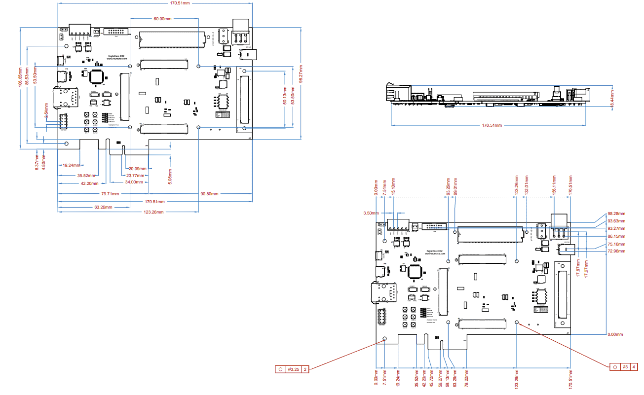
Physical Dimensions