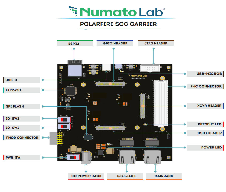
Introduction
The EagleCore PolarFire SoC SOM Carrier is equipped with Samtec Razor Beam LSHM Series connectors, allowing seamless integration with Microchip SOM modules, including the EagleCore PolarFire SoC. It also features a High Pin Count (HPC) high-speed FMC connector with four SERDES lines, enabling the expansion of the board’s capabilities through custom or off-the-shelf daughter boards. Additionally, the carrier board includes several other features aimed at enhancing functionality and providing greater flexibility for users.
Board Features
- 3 x Samtec Razor Beam LSHM Series connectors
- FTDI FT2232H for FPGA and Host communication
- 2 x RJ45 JACK
- USB Type-C connector
- USB micro-B connector for OTG communication
- 12V DC power supply
- Microchip-compatible JTAG Header for programming and debugging.
- FMC connector with a maximum of 100 IOs for a user-defined purpose
- FMC HPC connector with a maximum of 4 x SERDES lines
- ESP32
- 6×2 Header for user-configurable purpose
How to use EagleCore PolarFire SoC SOM Carrier
The following sections describe how to use this module in detail.
Hardware Accessories Required
In addition to the module, you may require the accessories listed below for a convenient and expedited installation:
- 12 V DC Power Supply
- USB A to USB-C cable.
- Micro B USB cable
- Flash pro 5/6 programmer
Connection Diagram
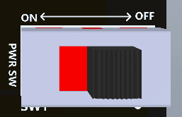
Power Switch
The Power Switch (SW1)is used to switch on/off the board. Sliding it to ON to supply power from the External DC Jack to the board. Sliding it to OFF to power off the board.
DC Power Supply
The EagleCore PolarFire SoC SOM Carrier is configured to use power from the DC power supply by connecting it to the

External DC Jack (J1). The external power supply should be in the range of +12V 5A.
Power LED
The EagleCore PolarFire SoC SOM Carrier has a power LED (PWR) that will illuminate when the board receives sufficient power during startup.
Reset
The EagleCore SOM Carrier has a push button switch (SW2) for resetting the entire system. This pin is connected to the system reset pin of the FPGA.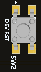
Gigabit Ethernet Port
The EagleCore PolarFire SoC SOM Carrier supports 2 Gigabit Ethernet communication lanes (J3 & J2), which support 10/100/1000Mbps Ethernet interface. It also has an additional Activity and Link LED for providing a visual indication to the user about the status of the Ethernet. The Ethernet LINK LED indicates the presence of a network connection when illuminated, while the Gigabit Ethernet ACTIVITY LED signals active data transmission or reception over the network.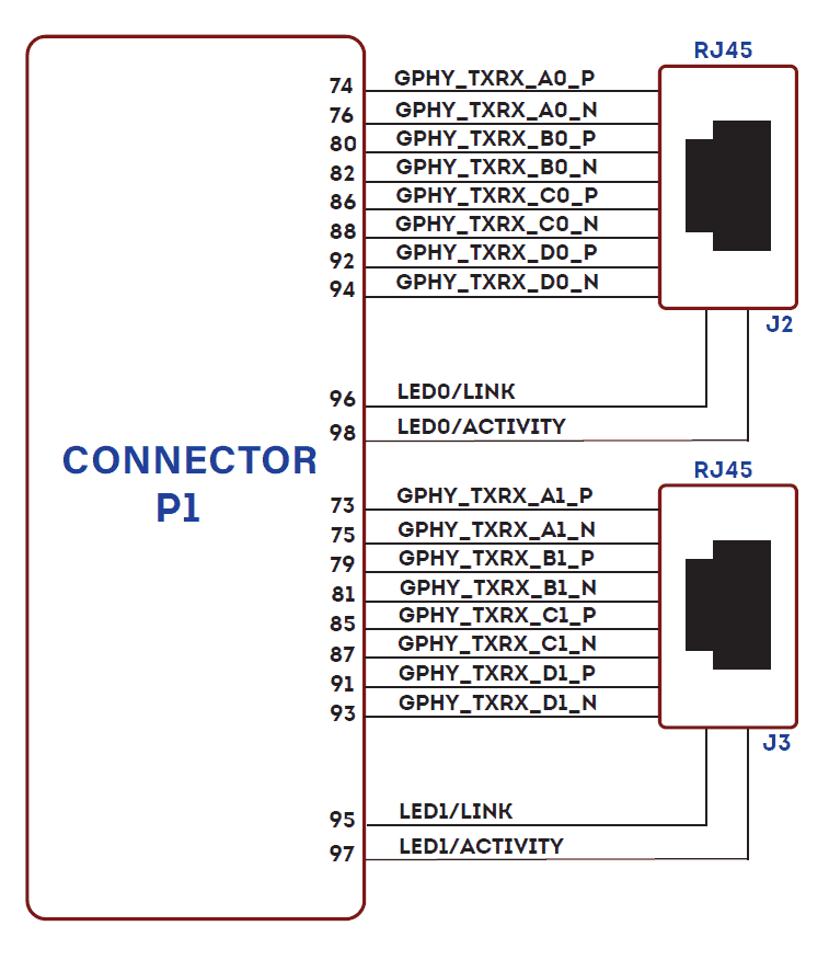
USB 2.0 OTG Connector
The EagleCore SOM Carrier provides a USB 2.0 OTG interface (P8) and can be accessed using a Micro-B
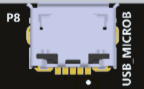
connector. USB OTG supports both Host, Device, and OTG modes based on the configuration made in the USB ID pin. An LED (USB_5V) is connected to the USB_5V as an indication of the presence of the VBUS in the USB pin.
USB Interface
The onboard USB connector (P15) helps a PC/Linux/Mac computer to communicate with this module.
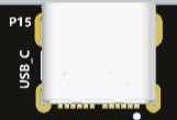 Use a USB Type-C cable to connect with a PC. This port will act as both a JTAG and UART interface.
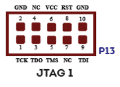
JTAG Header
EagleCore SOM Carrier supports FlashPro 5/6 standard JTAG Headers for programming and debugging purposes.
IO Reset & BOOT Switch
SW4 is labeled as the IO Reset, but it functions as a user-configurable pin. On the other hand, SW3 is connected to the BOOT pin of the FPGA.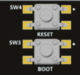
FMC Header
EagleCore PolarFire SoC SOM Carrier features a high-speed, high-pin-count FMC connector, which can be used to provide additional features and capabilities to it using custom or commercial-off-the-shelf daughter boards. Apart from IOs, 4 GTX lanes are available via an FMC connector for custom purposes.
FMC BANKS A TO E
| A | FMC Pin Name | FPGA PIN | B | FMC Pin Name | FPGA PIN | C | FMC Pin Name | FPGA PIN | D | FMC Pin Name | FPGA PIN | E | FMC Pin Name | FPGA PIN |
|---|---|---|---|---|---|---|---|---|---|---|---|---|---|---|
| A1 | GND | B1 | GND | C1 | GND | D1 | PG_C2M | E1 | GND | |||||
| A2 | FMC_DP1_M2C_P | K22 | B2 | GND | C2 | FMC_DP0_C2M_P | F22 | D2 | GND | E2 | FMC_HA01_P | AA21 | ||
| A3 | FMC_DP1_M2C_N | K21 | B3 | GND | C3 | FMC_DP0_C2M_N | F21 | D3 | GND | E3 | FMC_HA01_N | AA22 | ||
| A4 | GND | B4 | NC | C4 | GND | D4 | FMC_GBTCLK0_M2C_P | N19 | E4 | GND | ||||
| A5 | GND | B5 | NC | C5 | GND | D5 | FMC_GBTCLK0_M2C_N | N20 | E5 | GND | ||||
| A6 | FMC_DP2_M2C_P | M22 | B6 | GND | C6 | FMC_DP0_M2C_P | G20 | D6 | GND | E6 | FMC_HA05_P | AB19 | ||
| A7 | FMC_DP2_M2C_N | M21 | B7 | GND | C7 | FMC_DP0_M2C_N | G19 | D7 | GND | E7 | FMC_HA05_N | AB20 | ||
| A8 | GND | B8 | NC | C8 | GND | D8 | FMC_LA01_P | G17 | E8 | GND | ||||
| A9 | GND | B9 | NC | C9 | GND | D9 | FMC_LA01_N | H17 | E9 | FMC_HA09_P | AB17 | |||
| A10 | FMC_DP3_M2C_P | R20 | B10 | GND | C10 | FMC_LA06_P | G15 | D10 | GND | E10 | FMC_HA09_N | AA17 | ||
| A11 | FMC_DP3_M2C_N | R19 | B11 | GND | C11 | FMC_LA06_N | H15 | D11 | FMC_LA05_P | C19 | E11 | GND | ||
| A12 | GND | B12 | FMC_DP7_M2C_P | C12 | GND | D12 | FMC_LA05_N | C20 | E12 | FMC_HA13_P | T17 | |||
| A13 | GND | B13 | FMC_DP7_M2C_N | C13 | GND | D13 | GND | E13 | FMC_HA13_N | U17 | ||||
| A14 | FMC_DP4_M2C_P | B14 | GND | C14 | FMC_LA10_P | E13 | D14 | FMC_LA09_P | A16 | E14 | GND | |||
| A15 | FMC_DP4_M2C_N | B15 | GND | C15 | FMC_LA10_N | F13 | D15 | FMC_LA09_N | A17 | E15 | FMC_HA16_P | AB14 | ||
| A16 | GND | B16 | FMC_DP6_M2C_P | C16 | GND | D16 | GND | E16 | FMC_HA16_N | AB15 | ||||
| A17 | GND | B17 | FMC_DP6_M2C_N | C17 | GND | D17 | FMC_LA13_P | B13 | E17 | GND | ||||
| A18 | FMC_DP5_M2C_P | B18 | GND | C18 | FMC_LA14_P | C10 | D18 | FMC_LA13_N | B14 | E18 | FMC_HA20_P | V17 | ||
| A19 | FMC_DP5_M2C_N | B19 | GND | C19 | FMC_LA14_N | C9 | D19 | GND | E19 | FMC_HA20_N | V16 | |||
| A20 | GND | B20 | FMC_GBTCLK1_M2C_P | J19 | C20 | GND | D20 | FMC_LA17_P | C6 | E20 | GND | |||
| A21 | GND | B21 | FMC_GBTCLK1_M2C_N | J20 | C21 | GND | D21 | FMC_LA17_N | C7 | E21 | NC | |||
| A22 | FMC_DP1_C2M_P | H22 | B22 | GND | C22 | FMC_LA16_P | F15 | D22 | GND | E22 | NC | |||
| A23 | FMC_DP1_C2M_N | H21 | B23 | GND | C23 | FMC_LA16_N | G14 | D23 | FMC_LA23_P | D9 | E23 | GND | ||
| A24 | GND | B24 | NC | C24 | GND | D24 | FMC_LA23_N | D8 | E24 | NC | ||||
| A25 | GND | B25 | NC | C25 | GND | D25 | GND | E25 | NC | |||||
| A26 | FMC_DP2_C2M_P | P22 | B26 | GND | C26 | NC | D26 | NC | E26 | GND | ||||
| A27 | FMC_DP2_C2M_N | P21 | B27 | GND | C27 | NC | D27 | NC | E27 | NC | ||||
| A28 | GND | B28 | NC | C28 | GND | D28 | GND | E28 | NC | |||||
| A29 | GND | B29 | NC | C29 | GND | D29 | JTAG_TCK | E29 | GND | |||||
| A30 | FMC_DP3_C2M_P | T22 | B30 | GND | C30 | SCL_FMC | B8 | D30 | M_JTAG_TDO | E30 | NC | |||
| A31 | FMC_DP3_C2M_N | T21 | B31 | GND | C31 | SDA_FMC | A8 | D31 | FMC_TDO | E31 | NC | |||
| A32 | GND | B32 | FMC_DP7_C2M_P | C32 | GND | D32 | 3V3AUX | E32 | GND | |||||
| A33 | GND | B33 | FMC_DP7_C2M_N | C33 | GND | D33 | JTAG_TMS | E33 | NC | |||||
| A34 | FMC_DP4_C2M_P | B34 | GND | C34 | GND | D34 | JTAG_RST | E34 | NC | |||||
| A35 | FMC_DP4_C2M_N | B35 | GND | C35 | P12V0 | D35 | 3V3AUX | E35 | GND | |||||
| A36 | GND | B36 | FMC_DP6_C2M_P | C36 | GND | D36 | P3V3 | E36 | NC | |||||
| A37 | GND | B37 | FMC_DP6_C2M_N | C37 | P12V0 | D37 | GND | E37 | NC | |||||
| A38 | FMC_DP5_C2M_P | B38 | GND | C38 | GND | D38 | P3V3 | E38 | GND | |||||
| A39 | FMC_DP5_C2M_N | B39 | GND | C39 | P3V3 | D39 | GND | E39 | VADJ | |||||
| A40 | GND | B40 | NC | C40 | GND | D40 | P3V3 | E40 | GND |
FMC BANKS G TO K
| F | FMC Pin Name | FPGA PIN | G | FMC Pin Name | FPGA PIN | H | FMC Pin Name | FPGA PIN | J | FMC Pin Name | FPGA PIN | K | FMC Pin Name | FPGA PIN |
|---|---|---|---|---|---|---|---|---|---|---|---|---|---|---|
| F1 | PG_M2C | G1 | GND | H1 | NC | J1 | GND | K1 | NC | |||||
| F2 | GND | G2 | NC | H2 | PRSNT_M2C_L | D4 | J2 | NC | K2 | GND | ||||
| F3 | GND | G3 | NC | H3 | GND | J3 | NC | K3 | GND | |||||
| F4 | FMC_HA00_P | W22 | G4 | GND | H4 | NC | J4 | GND | K4 | NC | ||||
| F5 | FMC_HA00_N | V22 | G5 | GND | H5 | NC | J5 | GND | K5 | NC | ||||
| F6 | GND | G6 | FMC_LA00_P | E19 | H6 | GND | J6 | FMC_HA03_P | AB21 | K6 | GND | |||
| F7 | FMC_HA04_P | V20 | G7 | FMC_LA00_N | D19 | H7 | FMC_LA02_P | C22 | J7 | FMC_HA03_N | AA20 | K7 | FMC_HA02_P | W21 |
| F8 | FMC_HA04_N | V19 | G8 | GND | H8 | FMC_LA02_N | D22 | J8 | GND | K8 | FMC_HA02_N | V21 | ||
| F9 | GND | G9 | FMC_LA03_P | A20 | H9 | GND | J9 | FMC_HA07_P | U19 | K9 | GND | |||
| F10 | FMC_HA08_P | W19 | G10 | FMC_LA03_N | A21 | H10 | FMC_LA04_P | D21 | J10 | FMC_HA07_N | U18 | K10 | FMC_HA06_P | Y20 |
| F11 | FMC_HA08_N | W18 | G11 | GND | H11 | FMC_LA04_N | D20 | J11 | GND | K11 | FMC_HA06_N | Y21 | ||
| F12 | GND | G12 | FMC_LA08_P | C14 | H12 | GND | J12 | FMC_HA11_P | AA16 | K12 | GND | |||
| F13 | FMC_HA12_P | Y19 | G13 | FMC_LA08_N | C15 | H13 | FMC_LA07_P | B21 | J13 | FMC_HA11_N | Y16 | K13 | FMC_HA10_P | W16 |
| F14 | FMC_HA12_N | Y18 | G14 | GND | H14 | FMC_LA07_N | B22 | J14 | GND | K14 | FMC_HA10_N | W17 | ||
| F15 | GND | G15 | FMC_LA12_P | A15 | H15 | GND | J15 | FMC_HA14_P | AB18 | K15 | GND | |||
| F16 | FMC_HA15_P | Y15 | G16 | FMC_LA12_N | B15 | H16 | FMC_LA11_P | G13 | J16 | FMC_HA14_N | AA18 | K16 | FMC_HA17_P | AA13 |
| F17 | FMC_HA15_N | AA15 | G17 | GND | H17 | FMC_LA11_N | H13 | J17 | GND | K17 | FMC_HA17_N | AB13 | ||
| F18 | GND | G18 | FMC_LA16_P | F15 | H18 | GND | J18 | FMC_HA18_P | Y14 | K18 | GND | |||
| F19 | FMC_HA19_P | V14 | G19 | FMC_LA16_N | G14 | H19 | FMC_LA15_P | A7 | J19 | FMC_HA18_N | W14 | K19 | FMC_HA21_P | AA12 |
| F20 | FMC_HA19_N | V15 | G20 | GND | H20 | FMC_LA15_N | B7 | J20 | GND | K20 | FMC_HA21_N | AB12 | ||
| F21 | GND | G21 | FMC_LA20_P | H12 | H21 | GND | J21 | FMC_HA22_P | U12 | K21 | GND | |||
| F22 | NC | G22 | FMC_LA20_N | G12 | H22 | FMC_LA19_P | B10 | J22 | FMC_HA22_N | T12 | K22 | FMC_HA23_P | W13 | |
| F23 | NC | G23 | GND | H23 | FMC_LA19_N | B9 | J23 | GND | K23 | FMC_HA23_N | Y13 | |||
| F24 | GND | G24 | FMC_LA22_P | C4 | H24 | GND | J24 | NC | K24 | GND | ||||
| F25 | NC | G25 | FMC_LA22_N | B4 | H25 | FMC_LA21_P | F12 | J25 | NC | K25 | NC | |||
| F26 | NC | G26 | GND | H26 | FMC_LA21_N | F11 | J26 | GND | K26 | NC | ||||
| F27 | GND | G27 | NC | H27 | GND | J27 | NC | K27 | GND | |||||
| F28 | NC | G28 | NC | H28 | FMC_LA24_P | E10 | J28 | NC | K28 | NC | ||||
| F29 | NC | G29 | GND | H29 | FMC_LA24_N | F10 | J29 | GND | K29 | NC | ||||
| F30 | GND | G30 | NC | H30 | GND | J30 | NC | K30 | GND | |||||
| F31 | NC | G31 | NC | H31 | NC | J31 | NC | K31 | NC | |||||
| F32 | NC | G32 | GND | H32 | NC | J32 | GND | K32 | NC | |||||
| F33 | GND | G33 | NC | H33 | GND | J33 | NC | K33 | GND | |||||
| F34 | NC | G34 | NC | H34 | NC | J34 | NC | K34 | NC | |||||
| F35 | NC | G35 | GND | H35 | NC | J35 | GND | K35 | NC | |||||
| F36 | GND | G36 | NC | H36 | GND | J36 | NC | K36 | GND | |||||
| F37 | NC | G37 | NC | H37 | NC | J37 | NC | K37 | NC | |||||
| F38 | NC | G38 | GND | H38 | NC | J38 | GND | K38 | NC | |||||
| F39 | GND | G39 | VADJ | H39 | GND | J39 | NC | K39 | GND | |||||
| F40 | VADJ | G40 | GND | H40 | VADJ | J40 | GND | K40 | NC |
FMC Technical Specifications
| Parameter | Value | Unit |
|---|---|---|
| Power supply voltage | 12 | V |
| Number of positions | 400 | |
| Number of rows | 10 | |
| Height above the board | 6.55 | mm |
| Pitch | 1.27 | mm |
| Number of connectors | 1 | |
| FMC connector | ASP-134486-01 |
FMC Present LED
The EagleCore SOM Carrier has a dedicated pin for the FMC present signal, which is connected to the LED (PRSNT). This LED serves as an indicator for the user to verify that the FMC Mezzanine Module is inserted properly. If the FMC is properly inserted, the LED will illuminate.
SOM Connector Header
CONNECTOR P4
| Pin No. | Signal Name | Pin Name | Pin No. | Signal Name | Pin Name |
|---|---|---|---|---|---|
| 1 | VDD3V3 | VDD3V3 | 2 | VDD2V5 | M_VDD2V5 |
| 3 | VDD3V3 | VDD3V3 | 4 | VDD2V5 | M_VDD2V5 |
| 5 | GND | GND | 6 | GND | GND |
| 7 | DP0_CLK0_P | FMC_GBTCLK1_M2C_P | 8 | DP0_CLK0_P | FMC_GBTCLK0_M2C_P |
| 9 | DP0_CLK0_N | FMC_GBTCLK1_M2C_N | 10 | DP0_CLK0_N | FMC_GBTCLK0_M2C_N |
| 11 | GND | GND | 12 | GND | GND |
| 13 | DP0_TX0_P | FMC_DP0_C2M_P | 14 | DP0_RX0_P | FMC_DP0_M2C_P |
| 15 | DP0_TX0_N | FMC_DP0_C2M_N | 16 | DP0_RX0_N | FMC_DP0_M2C_N |
| 17 | GND | GND | 18 | GND | GND |
| 19 | DP0_TX1_P | FMC_DP1_C2M_P | 20 | DP0_RX1_P | FMC_DP1_M2C_P |
| 21 | DP0_TX1_N | FMC_DP1_C2M_N | 22 | DP0_RX1_N | FMC_DP1_M2C_N |
| 23 | GND | GND | 24 | GND | GND |
| 25 | DP0_TX2_P | FMC_DP2_C2M_P | 26 | DP0_RX2_P | FMC_DP2_M2C_P |
| 27 | DP0_TX2_N | FMC_DP2_C2M_N | 28 | DP0_RX2_N | FMC_DP2_M2C_N |
| 29 | GND | GND | 30 | GND | GND |
| 31 | DP0_TX3_P | FMC_DP3_C2M_P | 32 | DP0_RX3_P | FMC_DP3_M2C_P |
| 33 | DP0_TX3_N | FMC_DP3_C2M_N | 34 | DP0_RX3_N | FMC_DP3_M2C_N |
| 35 | GND | GND | 36 | GND | GND |
| 37 | DP1_CLK1_P | NC | 38 | DP1_CLK1_P | NC |
| 39 | DP1_CLK1_N | NC | 40 | DP1_CLK1_N | NC |
| 41 | GND | GND | 42 | GND | GND |
| 43 | DP1_TX0_P | FMC_DP4_C2M_P | 44 | DP1_RX0_P | FMC_DP4_M2C_P |
| 45 | DP1_TX0_N | FMC_DP4_C2M_N | 46 | DP1_RX0_N | FMC_DP4_M2C_N |
| 47 | GND | GND | 48 | GND | GND |
| 49 | DP1_TX1_P | FMC_DP5_C2M_P | 50 | DP1_RX1_P | FMC_DP5_M2C_P |
| 51 | DP1_TX1_N | FMC_DP5_C2M_N | 52 | DP1_RX1_N | FMC_DP5_M2C_N |
| 53 | GND | GND | 54 | GND | GND |
| 55 | DP1_TX2_P | FMC_DP6_C2M_P | 56 | DP1_RX0_P | FMC_DP6_M2C_P |
| 57 | DP1_TX2_N | FMC_DP6_C2M_N | 58 | DP1_RX0_N | FMC_DP6_M2C_N |
| 59 | GND | GND | 60 | GND | GND |
| 61 | DP1_TX3_P | FMC_DP7_C2M_P | 62 | DP1_RX3_P | FMC_DP7_M2C_P |
| 63 | DP1_TX3_N | FMC_DP7_C2M_N | 64 | DP1_RX3_N | FMC_DP7_M2C_N |
| 65 | GND | GND | 66 | GND | GND |
| 67 | DP2_CLK3_P | NC | 68 | DP2_CLK3_P | NC |
| 69 | DP2_CLK3_N | NC | 70 | DP2_CLK3_N | NC |
| 71 | GND | GND | 72 | GND | GND |
| 73 | DP2_TX0_P | ETH_TXVA_1_P | 74 | DP2_RX0_P | ETH_TXVA_0_P |
| 75 | DP2_TX0_N | ETH_TXVA_1_N | 76 | DP2_RX0_N | ETH_TXVA_0_N |
| 77 | GND | GND | 78 | GND | GND |
| 79 | DP2_TX1_P | ETH_TXVB_1_P | 80 | DP2_RX1_P | ETH_TXVB_0_P |
| 81 | DP2_TX1_N | ETH_TXVB_1_N | 82 | DP2_RX1_N | ETH_TXVB_0_N |
| 83 | GND | GND | 84 | GND | GND |
| 85 | DP2_TX2_P | ETH_TXVC_1_P | 86 | DP2_RX2_P | ETH_TXVC_0_P |
| 87 | DP2_TX2_N | ETH_TXVC_1_N | 88 | DP2_RX2_N | ETH_TXVC_0_N |
| 89 | GND | GND | 90 | GND | GND |
| 91 | DP2_TX3_P | ETH_TXVD_1_P | 92 | DP2_RX3_P | ETH_TXVD_0_P |
| 93 | DP2_TX3_N | ETH_TXVD_1_N | 94 | DP2_RX3_N | ETH_TXVD_0_N |
| 95 | RES | RJ45_LED1_0 | 96 | RES | RJ45_LED0_0 |
| 97 | RES | RJ45_LED1_1 | 98 | RES | RJ45_LED0_1 |
| 99 | GND | GND | 100 | GND | GND |
CONNECTOR P5
| Pin No. | Signal Name | Pin Name | Pin No. | Signal Name | Pin Name |
|---|---|---|---|---|---|
| 1 | VIN | VCC5V0 | 2 | VIN | VCC5V0 |
| 3 | VIN | VCC5V0 | 4 | VIN | VCC5V0 |
| 5 | VIN | VCC5V0 | 6 | VIN | VCC5V0 |
| 7 | GND | GND | 8 | GND | GND |
| 9 | GND | GND | 10 | GND | GND |
| 11 | VDD3V3 | M_VDDGPIO | 12 | VCC | VDD3V3 |
| 13 | VDD3V3 | M_VDDGPIO | 14 | VCC | VDD3V3 |
| 15 | GND | 16 | GND | GND | |
| 17 | IO2_P | FMC_LA02_P | 18 | IO0_CC_P | FMC_LA00_P |
| 19 | IO2_N | FMC_LA02_N | 20 | IO0_CC_N | FMC_LA00_N |
| 21 | IO3_P | FMC_LA03_P | 22 | IO1_CC_P | FMC_LA01_P |
| 23 | IO3_N | FMC_LA03_N | 24 | IO1_CC_N | FMC_LA01_N |
| 25 | GND | GND | 26 | GND | GND |
| 27 | IO6_P | FMC_LA06_P | 28 | IO8_P | FMC_LA08_P |
| 29 | IO6_N | FMC_LA06_N | 30 | IO8_N | FMC_LA08_N |
| 31 | IO7_P | FMC_LA07_P | 32 | IO9_P | FMC_LA09_P |
| 33 | IO7_N | FMC_LA07_N | 34 | IO9_N | FMC_LA09_N |
| 35 | GND | GND | 36 | GND | GND |
| 37 | IO10_P | FMC_LA10_P | 38 | IO8_P | FMC_LA08_P |
| 39 | IO10_N | FMC_LA10_N | 40 | IO8_N | FMC_LA08_N |
| 41 | IO11_P | FMC_LA11_P | 42 | IO9_P | FMC_LA09_P |
| 43 | IO11_N | FMC_LA11_N | 44 | IO9_N | FMC_LA09_N |
| 45 | GND | GND | 46 | GND | GND |
| 47 | IO14_P | FMC_LA14_P | 48 | IO12_P | FMC_LA12_P |
| 49 | IO14_N | FMC_LA14_N | 50 | IO12_N | FMC_LA12_N |
| 51 | IO15_P | FMC_LA15_P | 52 | IO13_P | FMC_LA13_P |
| 53 | IO15_N | FMC_LA15_N | 54 | IO13_N | FMC_LA13_N |
| 55 | GND | GND | 56 | GND | GND |
| 57 | IO18_CC_P | FMC_LA18_P | 58 | IO16_P | FMC_LA16_P |
| 59 | IO18_CC_N | FMC_LA18_N | 60 | IO16_N | FMC_LA16_N |
| 61 | IO19_P | FMC_LA19_P | 62 | IO17_CC_P | FMC_LA17_P |
| 63 | IO19_N | FMC_LA19_N | 64 | IO17_CC_N | FMC_LA17_N |
| 65 | GND | GND | 66 | GND | GND |
| 67 | IO22_P | SDA_FMC | 68 | IO20_P | FMC_LA20_P |
| 69 | IO22_N | SCL_FMC | 70 | IO20_N | FMC_LA20_N |
| 71 | IO23_P | FMC_LA22_P | 72 | IO21_P | FMC_LA21_P |
| 73 | IO23_N | FMC_LA22_N | 74 | IO21_N | FMC_LA21_N |
| 75 | GND | GND | 76 | GND | GND |
| 77 | IO26_P | FMC_LA24_P | 78 | IO24_P | FMC_LA23_P |
| 79 | IO26_N | FMC_LA24_N | 80 | IO24_N | FMC_LA23_N |
| 81 | GND | GND | 82 | GND | GND |
| 83 | CONFIG_SIG | NC | 84 | CONFIG_SIG | NC |
| 85 | CONFIG_SIG | NC | 86 | CONFIG_SIG | NC |
| 87 | CONFIG_SIG | OTG_USB_ID | 88 | CONFIG_SIG | OTG_D_N |
| 89 | CONFIG_SIG | OTG_USB_5V | 90 | CONFIG_SIG | OTG_D_P |
| 91 | CONFIG_SIG | FPGA_TDO | 92 | CONFIG_SIG | FPGA_TDI |
| 93 | CONFIG_SIG | FPGA_TCK | 94 | CONFIG_SIG | FPGA_TMS |
| 95 | CONFIG_SIG | DEV_RST | 96 | CONFIG_SIG | FPGA_JTAG_RST |
| 97 | CONFIG_SIG | PG_ALL | 98 | CONFIG_SIG | PG_GOOD |
| 99 | GND | GND | 100 | GND | GND |
CONNECTOR P6
| Pin No. | Signal Name | Pin Name | Pin No. | Signal Name | Pin Name |
|---|---|---|---|---|---|
| 1 | VIN | VCC5V0 | 2 | VIN | VCC5V0 |
| 3 | VIN | VCC5V0 | 4 | VIN | VCC5V0 |
| 5 | VIN | VCC5V0 | 6 | VIN | VCC5V0 |
| 7 | GND | GND | 8 | GND | GND |
| 9 | GND | GND | 10 | GND | GND |
| 11 | VDD3V3 | VDD3V3 | 12 | VDD1V8 | M_VDD1V8 |
| 13 | VDD3V3 | VDD3V3 | 14 | VDD1V8 | M_VDD1V8 |
| 15 | GND | GND | 16 | GND | GND |
| 17 | IO2_P | FMC_HA02_P | 18 | IO0_CC_P | FMC_HA00_P |
| 19 | IO2_N | FMC_HA02_N | 20 | IO0_CC_N | FMC_HA00_N |
| 21 | IO3_P | FMC_HA03_P | 22 | IO1_CC_P | FMC_HA01_P |
| 23 | IO3_N | FMC_HA03_N | 24 | IO1_CC_N | FMC_HA01_N |
| 25 | GND | GND | 26 | GND | GND |
| 27 | IO6_P | FMC_HA06_P | 28 | IO4_P | FMC_HA04_P |
| 29 | IO6_N | FMC_HA06_N | 30 | IO4_N | FMC_HA04_N |
| 31 | IO7_P | FMC_HA07_P | 32 | IO5_P | FMC_HA05_P |
| 33 | IO7_N | FMC_HA07_N | 34 | IO5_N | FMC_HA05_N |
| 35 | GND | GND | 36 | GND | GND |
| 37 | IO10_P | FMC_HA10_P | 38 | IO8_P | FMC_HA08_P |
| 39 | IO10_N | FMC_HA10_N | 40 | IO8_N | FMC_HA08_N |
| 41 | IO11_P | FMC_HA11_P | 42 | IO9_P | FMC_HA09_P |
| 43 | IO11_N | FMC_HA11_N | 44 | IO9_N | FMC_HA09_N |
| 45 | GND | GND | 46 | GND | GND |
| 47 | IO14_P | FMC_HA14_P | 48 | IO12_P | FMC_HA12_P |
| 49 | IO14_N | FMC_HA14_N | 50 | IO12_N | FMC_HA12_N |
| 51 | IO15_P | FMC_HA15_P | 52 | IO13_P | FMC_HA13_P |
| 53 | IO15_N | FMC_HA15_N | 54 | IO13_N | FMC_HA13_N |
| 55 | GND | GND | 56 | GND | GND |
| 57 | IO18_P | FMC_HA18_P | 58 | IO16_P | FMC_HA16_P |
| 59 | IO18_N | FMC_HA18_N | 60 | IO16_N | FMC_HA16_N |
| 61 | IO19_P | FMC_HA19_P | 62 | IO17_CC_P | FMC_HA17_P |
| 63 | IO19_N | FMC_HA19_N | 64 | IO17_CC_N | FMC_HA17_N |
| 65 | GND | GND | 66 | GND | GND |
| 67 | IO22_P | FMC_HA22_P | 68 | IO20_P | FMC_HA20_P |
| 69 | IO22_N | FMC_HA22_N | 70 | IO20_N | FMC_HA20_N |
| 71 | IO23_P | FMC_HA23_P | 72 | IO21_P | FMC_HA21_P |
| 73 | IO23_N | FMC_HA23_N | 74 | IO21_N | FMC_HA21_N |
| 75 | GND | GND | 76 | GND | GND |
| 77 | IO26_P | CONN_4 | 78 | IO24_CC_P | CONN_0 |
| 79 | IO26_N | CONN_5 | 80 | IO24_CC_N | CONN_1 |
| 81 | IO27_P | CONN_6 | 82 | IO25_P | CONN_2 |
| 83 | IO27_N | CONN_7 | 84 | IO25_N | CONN_3 |
| 85 | GND | GND | 86 | GND | GND |
| 87 | MSSIOB4 | CONFIG_LED1 | 88 | IO28_P | IO_SWITCH1 |
| 89 | MSSIOB4 | CONFIG_LED2 | 90 | IO28_N | IO_SWITCH2 |
| 91 | MSSIOB2 | SPI_SS | 92 | MSSIOB2 | SPI_SCK |
| 93 | MSSIOB2 | SPI_MISO | 94 | MSSIOB2 | SPI_MOSI |
| 95 | MSSIOB2 | UART_RXD | 96 | MSSIOB2 | SWITCH3 |
| 97 | MSSIOB2 | PRSNT_M2C_L | 98 | MSSIOB2 | UART_TXD |
| 99 | GND | GND | 100 | GND | GND |
Technical Specification
| Parameter | Value | Unit |
|---|---|---|
| Basic Specification | ||
| Power supply voltage | 12 | V |
| Number of Positions | 100 | |
| Number of Rows | 2 | |
| Height above Board | 8 | mm |
| Pitch | .50 | mm |
| Mated Stacking Heights | 5, 6, 8 | mm |
| Samtec Razor Beam LSHM Series connector | 3 |
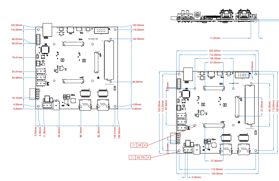
Physical Dimensions