
Introduction
Numato Lab’s 8 Channel PoE (Power over Ethernet) Relay Module (NL-ETHR-F-008) allows controlling electrical devices and electronic devices remotely through Ethernet. This is very helpful in those situations where the device that needs to be controlled is located far from the PC and thus cannot run through a USB cable. Numato Lab PoE Relay modules are designed to be very easy to set up and use. And as in the name, it doesn’t need a wire for power and data separately, one Ethernet cable serves both purposes!
Ease of use and wider operating system compatibility are the primary goals behind this product’s design. This simplicity allows the use of off-the-shelf Terminal Emulation programs such as Hyper Terminal and Tera Term for controlling the module with a simple set of human-readable commands through Telnet. Monitor and control the modules through a dedicated webpage, or just click on links to do the same. For power users, these modules can be controlled by writing programs in various programming languages.
Applications
- Home Automation
- Lighting Control
- Garden Equipment Control
- Industrial Automation
- Test Fixtures
- DIY and Hobby
Board Features
- 8 onboard 12V SPDT Relays (10A) with individual LEDs for status
- 8 digital inputs (12V)
- Separate Serial EEPROM(24AA02E48) with Globally Unique value used as MAC Address
- Reset Jumper: To reset the firmware on board to factory defaults
- Password-protected Web console, Telnet, HTTP communication interface
- LED indication for Power and individual relay status
- Relay contacts available on easy-to-access screw terminals
- Can be controlled from a web page, by using off-the-shelf Terminal Emulation programs, and custom applications through Telnet and HTTP.
Technical Specifications
| Parameter * | Value | Unit |
|---|---|---|
| Number of Relays | 8 | |
| Number of Digital Inputs | 8 | |
| Digital circuit power supply voltage (PoE) | 48 | V |
| Digital circuit power supply voltage (external) | 12 | V |
| Relay Specifications | ||
| Nominal relay coil voltage | 12 | V |
| Nominal coil power consumption (per relay) | 360 | mW |
| Relay contact material | Silver Alloy | |
| Contact rating | 1C: 7A 240VAC/ 10A 120VAC | |
| Maximum switching voltage | 250VAC/ 30VDC | |
| Maximum switching current | 10 | A |
| Maximum switching power | 270VAC/240W | |
| Life expectancy (Electrical) | 100,000 | Operations |
| Life expectancy (Mechanical) | 10,000,000 | Operations |
| Nominal insulation resistance | 100 Min at 500VDC | MΩ |
| Maximum switching on response time | 10 | mS |
| Maximum switching off response time | 5 | mS |
| Input Specifications | ||
| Minimum input voltage | 5.3 | V |
| Maximum input voltage | 12 | V |
* All parameters considered nominal. Numato Systems Pvt. Ltd. reserves the right to modify products without notice.
How to Use 8 Channel PoE Relay Module
It is very easy to set up and use the module. It needs only a Straight Through Ethernet cable for power and data flow. Use the dedicated web page to control and monitor the module, or just click the links according to the action required(HTTP) or use any off-the-shelf Terminal Emulators with the simple commands through Telnet.
Components/Tools Required
Along with the module, you may need the items in the list below for easy and fast installation.
1. 2 CAT 5e Ethernet Cable(Straight through cable)
2. USB Cable – A to B
3. PoE (Power over Ethernet) Injector
or
Ethernet switch (PoE supported)
Connection Details
-
- Connect one end of the ethernet cable to the PoE injector’s Data In and the other end to the switch or router.
- Connect the other ethernet cable from Data out to the 8 Channel PoE Relay Module.
- Power on the PoE Injector.
The module is connected to the PC through a USB Type B/PoE cable. The digital circuitry is powered by the PoE.
Factory Reset
Jumper P3 is used to reset the settings onboard to factory defaults. To execute the factory reset, please follow the steps below.
1. Power off the device.
2. Configure the FACT RESET Jumper to 2-3.
3. Power on the device.
4. Wait for 15-20 sec until the LED RJ3 onboard turns on.
5. Configure the FACT RESET Jumper back to 1-2.
6. Power off the board and back on.
7. Connect the USB Cable.
8. Using any serial emulation software connect to the COM Port and ENTER.
9. Login using the config user name and password as “admin” and send a “reboot” command.
10. LED RJ3 will turn off and you can see the config details in the terminal.
Please use this feature only for recovering the User name / Password. This action will reset the User Name, Password, Device ID, and also other settings as well. After reset, the board can be accessed using the default User name and Password.
The factory default settings will be as below table.
| User name | admin |
| Password | admin |
| Config user name | admin |
| Config Password | admin |
| Device ID | 00000000 |
| IP Address | 169.254.1.1 |
| Telnet Authentication | ON |
| Telnet Port | 23 |
| Access IP | Disabled |
| IP0 to IP9 | 255.255.255.255 |
| Access MAC | Disabled |
| MAC0 to MAC9 | FF FF FF FF FF FF |
| DHCP Status | Enabled |
Relay Contacts
Each relay has three contacts – C, NO, and NC. C is the common terminal and is used in both normally open (NO) and normally closed (NC) positions. All contacts on the relay are available externally on screw terminals for easy user access.
| Relay State | Connection between NC and C | Connection between NO and C |
|---|---|---|
| OFF | Close | Open |
| ON | Open | Close |
Configuring 8 Channel PoE Relay Module
Connect a PoE Injector and power up the device as mentioned in the Connection Details section above. A red LED (PWR) will glow which indicates active power. For configuration over USB, connect the module to PC through USB, and also connect the module to PoE Injector/Switch as mentioned in the section Connection details. The below commands can be used to configure the module using any serial terminal emulator software.
NB: By default, the module is configured with factory settings. To login to USB configuration settings users needs to send a reboot command from telnet or do a factory reset.
Configuration Command Set
| No. | Command | Usage | Description | |||
|---|---|---|---|---|---|---|
| 1 | usr | usr get | Reads username of the module in telnet mode. The default username is “admin”. | |||
| usr set xxxxxxxx | Assign username to the module for telnet mode, where ‘x’ can be any alphanumeric character. Username can be 1-8 characters length. |
|||||
| 2 | pass | pass get | Reads password of the module in telnet mode. The default username is “admin”. | |||
| pass set xxxxxxxx | Assign password to the module for telnet mode, where ‘x’ can be any alphanumeric character. Password can be 1-8 characters length. |
|||||
| 3 | config usr | config usr get | Reads username of the module in configuration mode. The default username is “admin”. | |||
| config usr set xxxxxxxx | Assign username to the module for configuration mode, where ‘x’ can be any alphanumeric character. Username can be 1-8 characters length. |
|||||
| 4 | config pass | config pass get | Reads password of the module in configuration mode. The default password is “admin”. | |||
| config pass set xxxxxxxx | Assign password to the module for configuration mode, where ‘x’ can be any alphanumeric character. Password can be 1-8 characters length. |
|||||
| 5 | telnet | telnet auth get | Read the status of telnet authentication. | |||
| telnet auth on/off | Enable and disable the telnet authentication. on – Enable , off - Disable |
|||||
| telnet port set xx | Assign the telnet port, where can be in the range of 00 to 99. The default port of telnet is 23. | |||||
| 6 | access | access ip get | Reads the stored IP addresses in the memory. Only these IP address can access the module if access ip is enabled. | |||
| access ip set N xxx.xxx.xxx.xxx | Save the acceptable IP in the network, where N can be in range of 0 to 9. Example : access ip set 8 192.168.10.120 |
|||||
| access ip on/off | Enable and disable the IP based access to the module. Once enabled, only the stored IP address can access the module on – Enable , off – Disable |
|||||
| access mac get | Reads the stored MAC address in the memory | |||||
| access mac set N XX XX XX XX XX XX | Save the MAC address for accessing the module, where N can be in range of 0 to 9. Example : access mac set 0 D4 93 98 D2 AF 34 |
|||||
| access mac on/off | Enable and disable the MAC based access to the module. Once enabled, only the stored MAC can access the module on – Enable , off – Disable |
|||||
| 7 | dhcp | dhcp on/off | Enable and disable the DHCP of the module on – Enable , off – Disable |
|||
| 8 | ip | ip get | Reads the status of DHCP and the static IP. If DHCP enabled, it displays only the DHCP status and if disabled, it displays the static IP too. | |||
| ip set xxx.xxx.xxx.xxx | Assign static IP to the module. DHCP should be disabled to set static IP. Example – ip set 192.168.10.120 | |||||
| 9 | mac id get | mac id get | Reads the MAC ID of the module. | |||
| 10 | reboot | reboot | Exit from configuration mode and enter to application mode. The module will be ready to start the telnet communication |
| 11 | relay poweron | relay poweron xx | Sets the relay status on power-on. Turn OFF and ON relays on power-on the module at each bit position according to the bits of the specified hexadecimal value. 0 – Turn OFF the relay , 1 – Turn ON the relay. relay poweron 5d, '5d' - 0101 1101, Turn ON relays 0,2,3,4 & 6, Turn OFF relays 1, 5 & 7. |
Sending Commands
One of the most powerful features of this module is the simple easy-to-use command set it supports. This command set allows for a very simple interface to access the features of the module through the TELNET protocol. The following sections give details of the command set and how to use the command set.
The Command Set
This product supports a very simple command set that is designed to be less cryptic and easy to use manually (using terminal emulation programs that support TELNET) or through a program written in one of the many supported languages.
List of currently supported commands.
| No. | Command | Parameter | Usage | Description |
|---|---|---|---|---|
| 1 | ver | None | ver | Returns firmware version |
| 2 | id | get | id get | Reads the module ID |
| set xxxxxxxx | id set 12345678 | Assign ID to the module | ||
| 3 | usr | get | usr get | Reads username |
| set xxxxxxxx | usr set admin | Assign username to the module | ||
| 4 | pass | get | pass get | Reads password |
| set xxxxxxxx | pass set admin | Assign password to the module | ||
| 5 | info | None | info | Device information |
| 6 | relay | version A0M01.01 ------------------------ on x version A0M02.01 ------------------------ on xxx | relay on 0 relay on 000 | Turn ON relays |
| version A0M01.01 ------------------------ off x version A0M02.01 ------------------------ off xxx | relay off 0 relay off 000 | Turn OFF relays |
||
| version A0M01.01 ------------------------ read x in version A0M02.01 --------------------------- read xxx | relay read 0 relay read 000 | Read relay status |
||
| readall | relay readall | Read all relays status at a time | ||
| writeall xx | relay writeall ff | Control all relays at a time | ||
| 7 | reset | None | reset | Reset all relays to default state |
| 8 | gpio | version A0M01.01 ------------------------ read x version A0M02.01 ------------------------ read xxx | gpio read 0 gpio read 000 | Read GPIO status |
| 9 | reboot | None | reboot | Exit to configuration mode |
The table below has more detailed information about available commands.
| No. | Command | Usage | Description |
|---|---|---|---|
| 1 | ver | ver | Returns firmware version. |
| 2 | id | id get | Reads the module ID. |
| id set xxxxxxxx | Assign ID to the module, where ‘x’ can be any alphanumeric character. ID should be 8 characters. | ||
| 3 | usr | usr get | Reads username of the module. |
| usr set xxxxxxxx | Assign username to the module, where ‘x’ can be any alphanumeric character. Username can be 1-8 characters length. | ||
| 4 | pass | pass get | Reads password of the module. |
| pass set xxxxxxxx | Assign password to the module, where ‘x’ can be any alphanumeric character. Password can be 1-8 characters length. | ||
| 5 | info | info | Returns device information. |
| 6 | relay | version A0M01.01 ---------------- relay on x version A0M02.01 ---------------- relay on XXX | Turn on the relay ‘x’, where x can be 0 to 7. relay on 0 - Turn on Relay 0. Turn on the relay 'XXX' where XXX can be 000 to 007. relay on 000 - Turn on Relay 0. |
| version A0M01.01 ---------------- relay off x version A0M02.01 ---------------- relay off XXX | Turn off the relay ’x’, where x can be 0 to 7. relay off 5 – Turn off Relay 5. Turn off the relay 'XXX', where x can be 000 to 007. relay off 005 – Turn off Relay 5. |
||
| version A0M01.01 ---------------- relay read x version A0M02.01 ---------------- relay read XXX | Read status of the relay ‘x’, where x can be 0 to 7. relay read 7 – Read status of Relay 7 and print either ‘on’ or ‘off’ depending on the status. Read status of the relay ‘XXX’, where XXX can be 000 to 007. relay read 007 – Read status of Relay 7 and print either ‘on’ or ‘off’ depending on the status. |
||
| relay readall | Read status of all relays in single operation. relay readall – Read all relay status and print xx. xx is a hexadecimal value, with binary 1 at positions for relays in ON state and 0 for relays in OFF state. |
||
| relay writeall xx | Control all relays in single operation. Turn OFF and ON relays at each bit position according to the bits of the specified hexadecimal value. 0 – Turn OFF the relay , 1 – Turn ON the relay relay writeall 5d. ‘5d’ – 0101 1101 - Turn ON relays 0,2,3,4 & 6, Turn OFF relays 1,5 & 7. |
||
| 7 | reset | reset | Reset by turning OFF all relays. |
| 8 | gpio | version A0M01.01 ---------------- gpio read x version A0M02.01 ---------------- gpio read XXX | Read status of the GPIO ‘x’, where x can be 0 to 7. gpio read 5 – Read status of GPIO 5 and print either ‘1’ or ‘0’ depending on the status. Read status of the GPIO ‘XXX’, where XXX can be 000 to 007. gpio read 005 – Read status of GPIO 5 and print either ‘1’ or ‘0’ depending on the status. |
| 9 | reboot | reboot | Exit from application mode and jump back to USB configuration mode. |
Accessing the Module
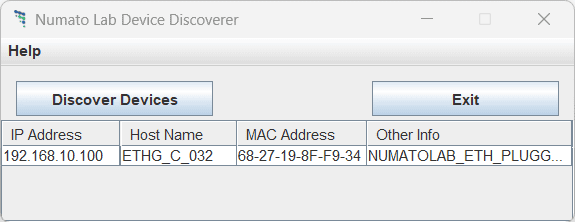
Run Numato Lab Device Discoverer.jar, and click on Discover Devices. The window will display the IP address, Host Name, MAC Address, and Other information. Note down the IP Address of the module.
This module allows communicating through the following ways
- TELNET
- HTML/Web Interface
- HTTP
TELNET
Simple easy-to-use commands are sent through TELNET using any of the off-the-shelf terminal emulator software.
Refer documentation “Sending Commands to Numato Lab Ethernet/PoE Modules” to know more.
HTML/Web Interface
The other method for controlling the module is through a web page served from the device. Access the module using the IP address from any of the web browsers.
Refer documentation “Sending Commands to Numato Lab Ethernet/PoE Modules” to know more.
HTTP
Controlling the module by entering http links provided along with the device IP in the browser’s address bar is the other method.
Refer documentation >“Sending Commands to Numato Lab Ethernet/PoE Modules” to know more.
Additional Information
Using GPIO's with Switches
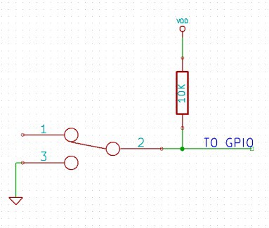
It is possible to read the position of a switch that is connected to a GPIO. An SPST or SPDT switch is recommended to use with GPIOs. Push switches do maintain the contacts closed only for a very short time so using them is discouraged. The fundamental idea of using a switch with GPIO is to have the switch cause a voltage level change at the GPIO pin when pressed. Usually, this is achieved by using an external pull-up resistor along with the switch. The pull-up resistor is connected between the GPIO and VDD and the switch is connected between the GPIO and the ground. When the switch is not pressed, the pull-up resistor will cause the GPIO to stay at the VDD voltage level. When the switch is pressed, the GPIO is short-circuited to the ground and stays at zero voltage. This change in voltage and thus the position of the switch can be read using the “gpio read” command. Please see the recommended connection diagram below.
Using Relay Modules with Inductive Loads
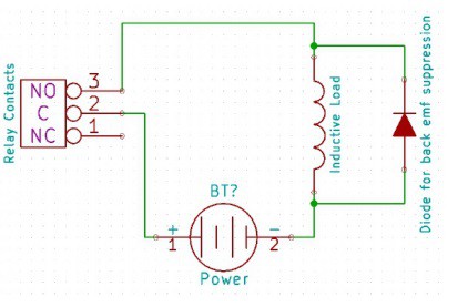
It is important to take additional care when using relays with inductive loads. An inductive load is pretty much anything that has a coil and works based on magnetic principles like Motors, Solenoids, and transformers. Inductive loads produce back EMF when the magnitude of the load current changes. The back EMF can be in the order of tens or even hundreds of voltage (See this Wikipedia article http://en.wikipedia.org/wiki/Counter-electromotive_force). This effect is most severe when power is disconnected from the inductive load because the rate of change of current is maximum at that point. Even though the back EMF lives only for a very short time (a few milliseconds) it can cause sparks between the relay contacts can deteriorate the contact quality over time and reduce the life span for the relays considerably.
So it is important to take countermeasures to suppress the back EMF to acceptable levels to protect relay contacts. Usually, this requires connecting electronic devices in parallel with the load such that they absorb the high-voltage components generated by the load. For solenoids, connecting a diode (fast switching diode is recommended) in parallel to the load (in the reverse direction to the load current) is very effective. A diode used for this purpose is usually called a freewheeling diode. Please see the diagram on the right for connection details.
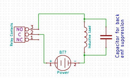
A capacitor with a proper rating is recommended for protecting the relay contacts when a motor is used as a load. The capacitor should be rated enough to withstand the back EMF that is generated by the motor. Please see the diagram below for connection details.
Please note that the relay modules are NOT shipped with back EMF suppression devices pre-installed. The exact kind of suppression device and the parameters of the selected device can vary depending on the load itself. Some of the parameters that affect the suppression device selection are the inductance of the load, power supply voltage, load current, physical size/structure of the load, etc. We can’t predict these parameters and design the required back EMF suppression device and incorporate that on the board. So we believe this is a task best left to the module user. There is an excellent article on designing back EMF suppression on Wikipedia at http://en.wikipedia.org/wiki/Flyback_diode
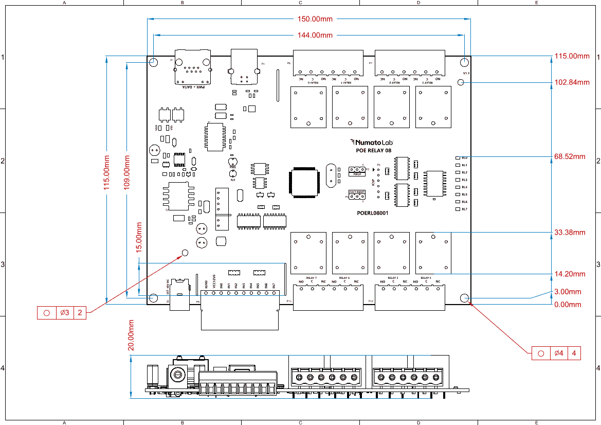
Mechanical Dimensions
Frequently Asked Questions (FAQs)
Q. What is the connector marked as ICSP on this module?
A. This connector is used to program the onboard microcontroller. This connector is primarily intended for factory use.
Q. I need a customized version of this product, can Numato do the customization for me?
A. Yes, we can definitely do customization but there may be minimum order requirements depending on the level of customization required. Please write to sales@numato.com for a quote.
Q. Where can I buy this product?
A. All Numato products can be ordered directly from our web store http://www.numato.com. We accept major credit cards and Paypal and ship to almost all countries with a few exceptions. We do have distributors in many countries where you can place your order. Please find the current list of distributors at http://numato.com/distrib.
Powering Up 8 Channel PoE Relay Module
Connect the LAN cable from a PoE switch. A red LED (PWR) will glow which indicates active power. Run Numato Lab Device Discoverer.jar, and click on Discover Devices. The window will display the IP address, Host Name, MAC Address, and Other information. Note down the IP Address of the module.
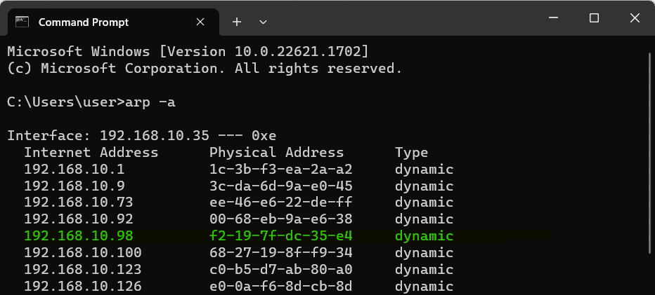
IP Address and MAC Address can be seen in the command prompt also, only after connecting the module through the web page. Open the command prompt and type the command ‘arp -a‘. This will display the available network interfaces and connected devices along with the MAC address and IP address of each device. Look for the IP address that corresponds to your device’s MAC address. The MAC address for each Relay Module is printed on a label on the board for your convenience. Use the IP address obtained in order to access the device.
 If the module is not discovering, it might be in configuration in mode (RJ3 LED – ON).