
Introduction
Numato Lab’s 4 Channel WiFi DAQ Module is designed for modern IoT, industrial, and smart automation applications. It combines powerful data acquisition capabilities with seamless cloud connectivity and local control features. With integrated support for Wi-Fi 2.4GHz, MQTT/MQTTS (compatible with AWS, Azure, and other cloud platforms), and REST API, the 4 Channel WiFi DAQ Module empowers users to monitor, control, and automate processes remotely and securely. This highly versatile device allows users to create fully automated systems with minimal setup time. It is ideal for both professionals and hobbyists looking to integrate reliable automation and data acquisition into their systems.
Applications
- Industrial Automation: Monitor sensor inputs and control actuators, machines, or alarms based on configurable logic.
- Smart Home & Building Automation: Automate lighting, HVAC systems, and appliances using environmental data and remote control.
- IoT & Cloud-Based Monitoring: Stream real-time data to AWS, Azure, or private MQTT brokers for centralized dashboards and alerting.
- Environmental Monitoring: Use the onboard temperature and humidity sensor for weather stations, greenhouses, or storage rooms.
- Remote Control Systems: Operate devices from anywhere using the onboard web server or REST APIs.
- Data Logging and Analytics: Log inputs, outputs, and sensor data locally for historical analysis and compliance tracking.
- Smart Agriculture: Monitor field conditions and control irrigation or other systems based on environmental triggers.
Board Features
- 4 Relay Outputs: Control external devices such as fans, alarms, or lighting with 4 independent relay channels.
- 4 Digital High Voltage Inputs supports Maximum Input Voltage of 24V
- 4 Analog Inputs with 16-bit Resolution
- 2-in-1 Sensor: Temperature and humidity sensing in a single device.
- Wi-Fi (2.4GHz): Provides stable wireless communication.
- DIN Rail Support: Supports standard DIN rail for easy installation.
- Cloud Integration: Supports MQTT, MQTTS for AWS, Azure, and more.
- Data Logging: Onboard Data Logging for secure, local storage of sensor and control data.
- Web Server & REST API: Built-in Web Server for configuration, monitoring, and remote control.
- Sensor and ADC Calibration: On-device calibration for accuracy.
- AP Mode for Device Configuration: Simplified configuration without a network.
- RGB Indicator: Easily shows device status with a color-coded RGB LED.
Technical Specifications
| Parameter | Value | Unit |
|---|---|---|
| Number of relays | 4 | |
| Number of GPIOs | 4 | |
| Number of ADCs | 4 | |
| Number of Sensors | 2 | |
| Power supply voltage (External) | 12 | V |
| Sensor Specifications | ||
| Temperature | Measurement Range: -40 to125 degree celsius. Typical Accuracy: +/- (1 degree celsius) | °C |
| Humidity | Measurement Range: 0% to 100% RH. Typical Accuracy: +/- (6% RH) from 15 to 35 degree celsius within 20% to 65% RH. +/- (9% RH) from -10 to 60 degree celsius across 0% to 100% RH. | % |
| Sensor response time | 1 | second |
| Digital Inputs Specifications | ||
| Minimum DI sink current | 2.05 | mA |
| Maximum DI sink current | 44 | mA |
| Recommended sink current | 10 | mA |
| Maximum Low Voltage (VIL) | 10.2 | V |
| Minimum High Voltage (VIH) | 10.5 | V |
| Maximum High Voltage | 24 | V |
| ADC Specifications | ||
| Resolution | 16 | bits |
| Full scale range | -10.24 to +10.24 | V |
| Reference voltage | 4.096 | V |
| Relay Specifications | ||
| Nominal relay coil voltage | 12 | V |
| Nominal coil power consumption (per relay) | 120 | mW |
| Relay contact material | Silver Alloy | |
| Contact rating | 5A/ 250V AC 5A/ 30V DC | |
| Maximum switching voltage | 245VAC/ 30VDC | |
| Maximum switching current | 5 | A |
| Maximum switching power | 250VA/ 150W | |
| Contact resistance (initial) | 100 | mΩ |
| Insulation resistance | 1000 | MΩ |
| Life expectancy (Electrical) | 1,00,000 | Operations (3A 250VAC/23VDC, Resistive load) |
| Life expectancy (Mechanical) | 20000000 | Operations |
| Maximum switching on response time | 1 | second |
| Maximum switching off response time | 9 | second |
| Shock resistance (Functional) | 98 | m/s2 |
| Shock resistance (Destructive) | 980 | m/s2 |
| Vibration resistance | 10Hz to 55Hz 1.5mm DA | |
| Other Information | ||
| USB Vendor ID | 0x2A19 | |
| USB Product ID | 0x0C12 | |
* All parameters considered nominal. Numato Systems Pvt Ltd reserve the right to modify products without notice.
How to use the module
The following section describes how to use this module.
Components/Tools required
Required Items for Easy and Fast Installation
To ensure a smooth and quick setup of the 4 Channel WiFi DAQ Module, please have the following items ready:
- A stable 12V DC power adapter with 1.5A current output is required to power the device safely and reliably.
- Wi-Fi Router (2.4GHz Support): A Wi-Fi router that supports the 2.4GHz frequency band for seamless connectivity.
Wi-Fi Interface
The 4 Channel WiFi DAQ Module offers effortless wireless connectivity with built-in 2.4GHz Wi-Fi, ensuring smooth and reliable network integration. With AP Mode, setup is quick and hassle-free, requiring no additional hardware. Once connected, the device efficiently transmits data to the cloud using MQTT/MQTTS, enabling real-time monitoring across multiple platforms. In STA Mode, once the device is configured, it will stay connected to the specified network and continuously publish data to the cloud, ensuring seamless data communication without the need for manual intervention. Secure access is provided through HTTP/HTTPS REST APIs, allowing for robust and real-time data communication. For added convenience, the module features a secure, built-in web interface that can be accessed directly from any browser for easy configuration and monitoring.
Power Supply
The 4 Channel WiFi DAQ Module operates on a 12V DC power supply with a minimum current rating of 1.5A, offering both convenience and reliability. For optimal performance, use a stable 12V adapter with a screw terminal for secure and consistent power delivery.
LED Indication
The 4 Channel WiFi DAQ Module has a multifunctional RGB LED Indicator. The device indicates the Power status, Configuration mode, Network status, MQTT connectivity, and Multipurpose switch state.
| Color | State | Indication |
|---|---|---|
| Red | Solid (2 seconds) | Device is powered on |
| Purple | Blinking | AP Mode: Waiting for STA Device to get conneted |
| Purple | Solid | AP Mode: STA Device is connected |
| Green | Blinking | Station Mode: Trying to connect to Wi-Fi network |
| Green | Solid | Station Mode: Connected to Wi-Fi network |
| Blue | Blinking | Trying to connect to MQTT broker / Not connected |
| Blue | Solid | Connected to MQTT broker |
| Blue + White Blink | Solid Blue with White Blinking in the Background | MQTT publishing is active — white LED blinks at every publish interval |
| Yellow | Solid | Falling back to AP (Configuration mode) |
| Red | Blinking | Factory reset initialized |
Multipurpose Switch
The 4 Channel WiFi DAQ Module is equipped with a versatile multipurpose switch that enables a range of device management functions:
| Action | LED Indication | Function |
|---|---|---|
| Single Click | Solid RED Indication | Device Reset: Resets the device and reinitializes. |
| Press for 5-7 seconds | Solid Yellow Indication | Configuration Mode: Device enters AP mode for device reconfiguration. |
| Press for 10-15 seconds until solid RED indication | Red LED Blinks | Factory Reset: Device erases all the settings and restores to factory defaults. |
Important: Use the Factory reset feature only to recover the Username/ Password/Hostname. A factory reset will erase all Network, MQTT, and other settings, restoring the board to its default configuration. After resetting, access the board using the default credentials listed in the table below.
The factory default settings will be as table below.
| Field | Description |
|---|---|
| User name | admin |
| Password | *Factory set default unique Password. |
| Host Name | *Factory set default unique Hostname. |
| IP Address | DHCP Enabled |
Configure 4 Channel WiFi DAQ Module
The 4 Channel WiFi DAQ Module offers a simple and hassle-free configuration process through its built-in Access Point (AP) mode. Follow these easy steps to get started:
Connect to the Access Point:
- Turn on the 4 Channel WiFi DAQ Module and wait for it to enter AP mode, a Purple LED blinks indicating that the device is in Configuration mode.
- On your PC or mobile device, go to the Wi-Fi settings and connect to the 4 Channel WiFi DAQ Module’s Wi-Fi network. The network name (SSID) will typically be “Default Hostname” and the network password will the “Default Password”.
- Once the connection is established successfully, a Solid Purple LED Indication is visible.
Access the Configuration Page:
- Open any web browser and enter the default IP address of the 4 Channel WiFi DAQ Module (192.168.4.1) in the address bar.
- When prompted, enter the default password to log in and access the device’s configuration interface.
Configure the Device:
- Once logged in, you can easily configure Wi-Fi settings, MQTT cloud integrations, control the relays, monitor digital inputs, and view real-time sensor and ADC data, all through the intuitive web interface.
Important Note: After you have saved all your settings on the device such as network, sensor, MQTT configurations, relay control settings, digital input monitoring, or ADC configurations the changes will only take effect after the device is rebooted. You can reboot the device either:
- From the Webpage: Use the Reboot option on the device management section to apply all settings.
- From the Multi-Functionality Switch: Single Click reboots the device with new configuration set.
Accessing the module
The 4 Channel WiFi DAQ Module can be monitored and configured through the following methods:
- Web Interface: Access the device’s web page for easy monitoring and configuration.
- REST API: Utilize the REST API for programmatic control and integration with other systems.
Accessing the module using web interface
The easiest method for controlling the module is through web page served from the device. To open the administration web page, type in the IP address in to the address bar of any web browser and press enter.
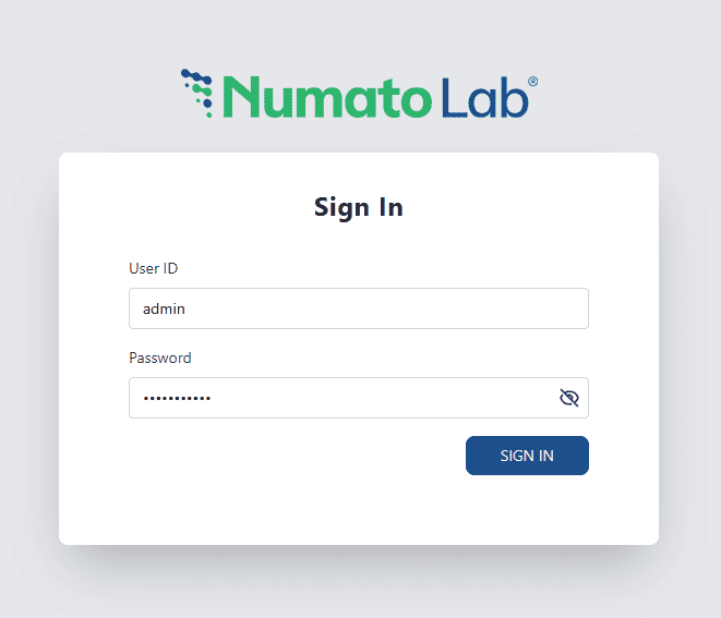
You will be prompted to enter Your username and Password. The default username is ‘admin,’ and the default password is unique for each device. Once logged in, you may change the username and Password.
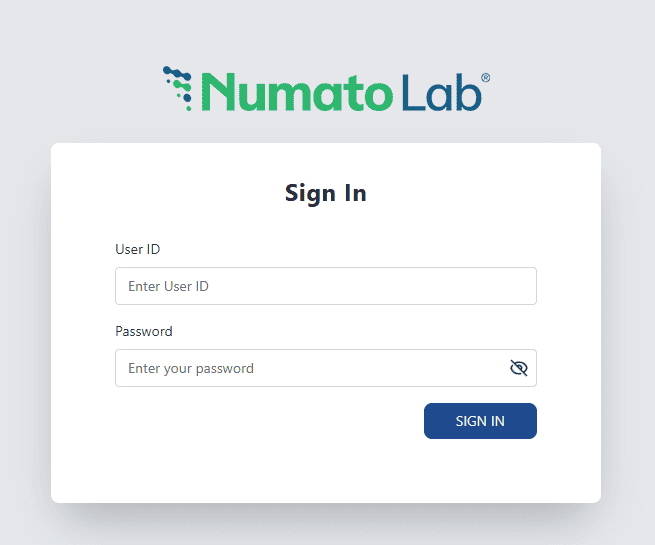
Enter the default User name and Password then click Sign In.
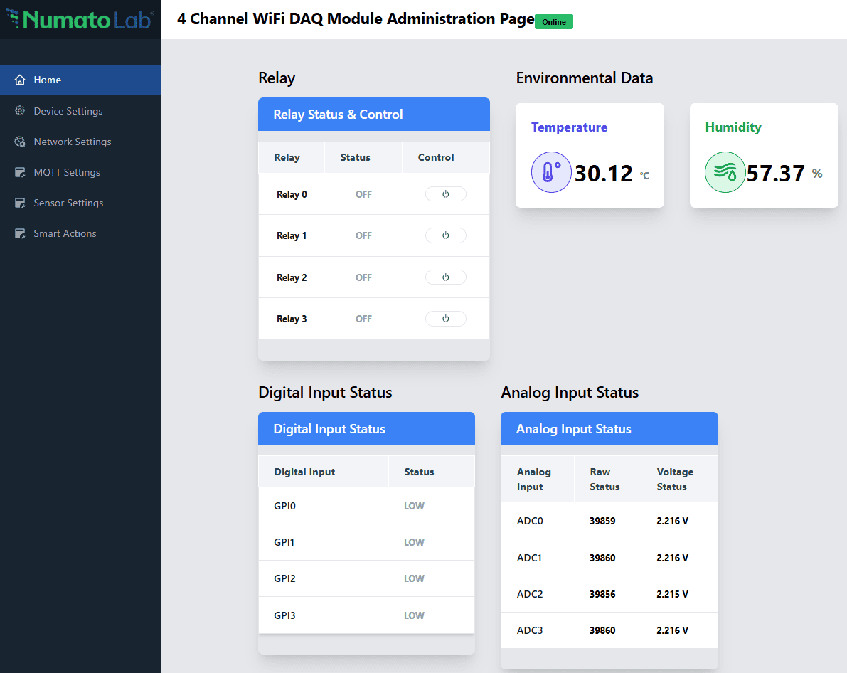
You will be presented with the device home page, where you can monitor sensor data, view the status of digital inputs and ADCs, and control the relays.
Device Settings
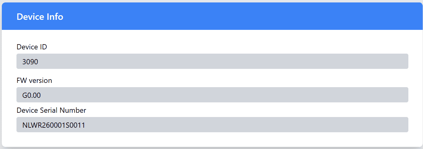
Device Info
The Device Info section provides detailed information about your device. This section is read-only, which means you cannot modify the device information here, but you can refer to it when needed.
| Field | Description |
|---|---|
| Device ID | Displays Device ID. |
| Firmware Version | Displays the current version of the firmware installed on your device. |
| Device Serial Number | The serial number specific to your device. This number is used for identification and support purposes. |
These details are displayed in a simple, easy-to-read format.
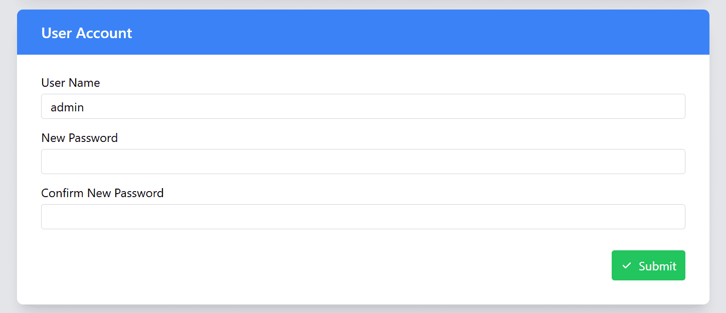
User Account
In the User Account section, you can manage your web login and Access Point credentials, including updating your Username and Password. This is important for keeping your account secure and ensuring only authorized users can access the device settings.
| Field | Description |
|---|---|
| Username | You can change your username by entering a new one in the provided field. Make sure to choose a unique and memorable username for easy access. |
| Password | Enter your new password here. Please follow the password strength requirements to ensure your password is strong and secure. |
| Confirm Password | Re-enter the new password here to confirm that both entries match. If they do not match, an error message will appear to help you correct it. |
Important Note: Your password will only be updated if both the New Password and Confirm Password fields match exactly. If there is a discrepancy, a Warning message will be displayed, you will need to correct it before proceeding.
Important Update Information: Once you update the User Account Password, both the web login password and the Access Point password will be updated simultaneously. This means that the new password will be used for both the web login to your device’s dashboard and for accessing the device through its wireless Access Point. Make sure to remember this new password for all future logins to your device.
OTA Firmware Update
The Firmware Update section allows you to keep your device up to date with the latest features and improvements.
Important: Do not upload any unauthorized images via OTA. Doing so may permanently damage the device.
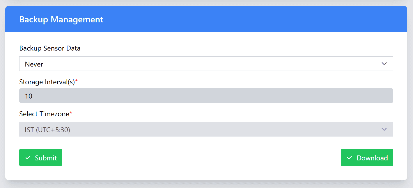
Backup Management
The Backup Management section allows you to configure how your device logs sensor data locally for future analysis. You can choose from five different logging scenarios, depending on your needs. This enables you to control when and how sensor data is captured and stored on the device. In addition to selecting the logging scenario, you can also set the backup interval and choose the timezone for timestamping the logs when the device is connected to the network.
- Logging Scenarios:
| Field | Description |
|---|---|
| Never | Disables local sensor data logging entirely. No data will be stored on the device. |
| Network Connected | Logs sensor data only when the device is connected to an access point. Data is captured only when network connectivity is active. |
| Network Disconnected | Logs sensor data whenever the device is disconnected or loses its connection to the configured network. This ensures data is captured during network interruptions. |
| MQTT Disconnected | Logs sensor data when the device loses connection to the MQTT/MQTTS broker, ensuring data is stored even during disruptions to real-time communication. |
| Always | Continuously logs data in both AP mode (Access Point mode) and STA mode (Station mode), providing the most comprehensive dataset for analysis. |
- Backup Interval: Set how often the device should back up sensor data. You can choose the interval that best suits your needs (e.g., every 10 minutes, hourly, or daily). The interval determines how frequently the device logs and saves the data to the local storage.
- Timezone for Log Timestamp: Select the timezone that should be used to timestamp the logged sensor data when the device is connected to the network. This ensures that the data is recorded with accurate timestamps based on your local time zone, making it easier to analyze data in the context of your region.
Note:The device logs sensor data up to 500,000 data entries. Once the data reaches this limit, the device automatically overwrites the oldest data, starting from the first row, in a circular ring-buffer fashion.
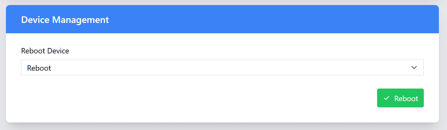
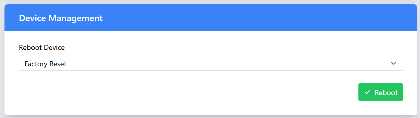
Device Management
In the Device Management section, you can perform essential actions to manage your device, including rebooting the device and restoring it to its factory settings.
| Action | Description |
|---|---|
| Reboot | This option allows you to reboot the device. Rebooting can be useful if you want to apply the new configurations to the device. |
| Factory reset | Performing a Factory Reset will restore the device to its original factory settings, erasing all user-configured data and settings. This includes: User data: All settings, including any customized configurations, calibrations, passwords, network settings, and MQTT settings, will be erased. Sensor logs: All logged sensor data stored on the device will be cleared. Restoration of factory defaults: The device will revert to its default settings as it was when it first came out of the box, including any default network settings, device names, and configurations. |
Important Note: Factory Reset is a permanent action. Once performed, all user-set data and logged sensor data will be erased. This action cannot be undone, make sure to back up any important data before performing a factory reset.
Network Settings
The Network Settings section allows you to configure the network connectivity of your device. This includes the
- Wi-Fi Access Point Settings.
- Wi-Fi Station Settings
- HTTPS certificate settings.
Wi-Fi Access Point Settings
In this section, you can view the SSID of the device’s Access Point. The SSID is a unique name assigned to each WiFi DAQ Device, allowing you to identify and connect to the device’s access point.
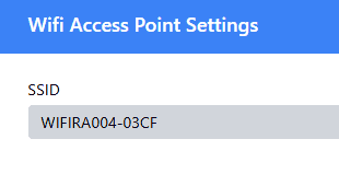
Note: The Password for the Access Point is the same as the User Account password. That is once you update your User Account password, The Access Point password will also be updated automatically.
Wi-Fi Station Settings
The WiFi Station Settings allow you to configure the device’s connection to an existing WiFi network. You can update the SSID, set the password, adjust the hostname, and configure the network settings according to your needs.
| Field | Description |
|---|---|
| SSID | Enter the SSID (network name) of the WiFi network that the device should connect to. This is the name of the wireless network that the device will search for and connect to. |
| Password | Enter the WiFi password for the SSID you've selected. This ensures secure communication between the device and your network. |
| Host Name | Set a unique hostname for the device. This is useful for identifying the device on the network and can be customized to reflect the device’s role or location. |
| MAC Address | Displays Device MAC Address. |
| DHCP IP | Enable DHCP: When enabled, the device will automatically receive its network settings. This option is suitable if you don't need a fixed IP address for the device. Disable DHCP: If you choose to disable DHCP, you will need to manually configure the device’s network settings. |
| Static IP | Static IP Configuration (only available when DHCP is disabled): Static IP: Enter a fixed IP address for the device. This ensures that the device always uses the same IP address, which can be important for consistent communication. Subnet Mask: Set the subnet mask for the network. This defines the network’s address space and helps devices identify which other devices are on the same network. Gateway: Enter the gateway IP address. This is typically the IP address of your router or another device that connects your local network to the internet or other networks. Primary DNS: Enter the primary DNS server address. This is used to resolve domain names into IP addresses. Secondary DNS: Optionally, enter a secondary DNS server address for redundancy. If the primary DNS server is unavailable, the device will use the secondary DNS server for name resolution. |
After configuration, the 4 Channel WiFi DAQ Module can be accessed via the DNS Hostname or the IP Address.
- Accessing via DNS Hostname:
- The device will be accessible via its DNS hostname. By default, the device will be configured with a device specific unique hostname. The device can be accessed with the postfix “.local” example:WIFIRA004-4733cf.local.
- Accessing via IP address:
-
If the device was configured with a static IP address, you can access it directly by entering the static IP address into your browser.
-
If the device was set to use dynamic IP (DHCP), you can either check the IP address assigned to the device through your router’s DHCP table or use a “arp -a” on command tool and check the IP assigned to your device MAC.
-
Note:
- It is essential for the device to be connected to the WiFi network, to establish a connection to the MQTT broker, allowing it to publish data. Without an active network connection, the device will not be able to communicate with the MQTT broker, and as a result, data cannot be transmitted or received.
- Make sure the device has a stable connection to the network for proper data logging and remote communication. This connection is crucial for maintaining real-time data updates and ensuring that your device interacts with other systems in your setup.
HTTPS Settings
The HTTPS Settings section allows you to configure secure communication for your device by enabling HTTPS. HTTPS is essential for encrypting the data transmitted between the device and the web dashboard, providing an extra layer of security for sensitive information.
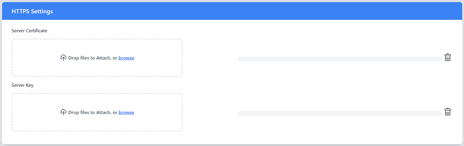
Configuration Requirements:
- Server Certificate: This is the SSL/TLS certificate that verifies the identity of the server and establishes a secure, encrypted connection.
- Server Key: The server key is the private key that corresponds to the server certificate. It is required to complete the encryption/decryption process for secure communication. This key should be kept confidential, as it is critical for maintaining the security of your HTTPS connection.
How to Configure:
- Obtain Server Certificate and Key: You must have a valid SSL/TLS certificate and its corresponding private key. These can be generated from a certificate authority (CA) or created using a self-signed certificate.
- Upload the Server Certificate and Key: Upload the server certificate and server key files in the respective fields. These will enable encrypted communication via HTTPS.
Important Notes:
- Security: Always ensure that the server key is kept secure and never shared publicly. If compromised, the security of the HTTPS communication will be at risk.
- Certificate Expiration: SSL/TLS certificates have an expiration date. Ensure that your certificate is valid and renewed before it expires to avoid loss of secure communication capabilities.
MQTT Settings
The MQTT/MQTTS Settings section allows you to configure the communication between your device and the MQTT broker. You can choose to use either MQTT (unencrypted) or MQTTS (secure, encrypted MQTT).
| Setting | Description | Mandatory for MQTT | Mandatory for MQTTS |
|---|---|---|---|
| Broker | Enter the MQTT broker address (IP or domain) with the appropriate protocol prefix (mqtt:// or mqtts://). For example, mqtt://broker.example.com or mqtts://broker.example.com. | YES | YES |
| Publish Interval (ms) | Set the publish interval in milliseconds. This defines how often the device will send data. | YES | YES |
| Client ID | Enter a unique Client ID for the device. This ID is used to identify the device on the MQTT broker. | YES | YES |
| Publish Topic | Define the topic for publishing data to the broker. Devices subscribing to this topic will receive the data. | YES | YES |
| Subscribe Topic | Define the topic that the device will subscribe to in order to receive incoming commands (e.g., to control relays). The expected message format is: {"relay":x,"state":y}, where x represents the relay number (ranging from 0 to 3) and y represents the desired relay state (0 for OFF, 1 for ON). For example, sending {"relay":0,"state":1} will turn ON Relay 0. | YES (if using control commands) | YES (if using control commands) |
| Message Format (To publish data) | Specify the format of the message being sent to the broker. For example: {Din:~din_val~, RL:~rl_val~,temp:~t0_val~, hum:~h0_val~, Ain0:~a0_val~, Ain1:~a1_val~, Ain2:~a2_val~, Ain3:~a3_val~}. The values ~din_val~, ~rl_val~, ~t0_val~, ~h0_val~, ~a0_val~, ~a1_val~, ~a2_val~, and ~a3_val~ will be replaced by the actual digital input number, relay number, temperature, humidity, and adc data from the device | YES | YES |
| Username | Enter the Username for authentication if the MQTT broker requires security. | YES, If security is required. | YES, If security is required. |
| Password | Enter the Password for authentication if the MQTT broker requires security. | YES, If security is required. | YES, If security is required. |
| CA Certificate | Upload the CA certificate used to verify the broker’s identity. This is required for secure MQTT communication (MQTTS). | NO | YES |
| Client Certificate | Upload the client certificate used to authenticate the device to the broker in secure communication (MQTTS). | NO | YES |
| Client Key | Upload the client key associated with the client certificate for encrypted communication (MQTTS). | NO | YES |
Sensor Settings
The Sensor Settings page allows users to calibrate the connected sensors to ensure accurate readings. Calibration is a crucial process to adjust sensor readings for environmental or operational factors that may affect their accuracy. Proper calibration helps to enhance measurement precision and ensures the data you receive is reliable.
-
RHT Sensor Settings:
Used for calibrating the internal Relative Humidity and Temperature (RHT) sensor. Adjustments here ensure accurate ambient readings by applying user-defined offsets. -
ADC Offset Settings:
This section allows calibration of analog voltage inputs. The ADC supports 14-bit resolution, i.e., values from -1683 to 16383, allowing fine-grained control over analog signal calibration.
| Sensor | Calibration Range | Description |
|---|---|---|
| Temperature (c) | +/- 10 degree celsius | Calibrate the temperature sensor to adjust for offsets in temperature measurements. This allows you to fine-tune the sensor's readings to align with a known reference. |
| Humidity (%) | +/- 10 % | Calibrate the humidity sensor to correct any drift in humidity readings. |
| ADC Offset (14-bit) | -16383 to 16383 | Calibrate the analog input channels by adjusting the offset to eliminate base voltage errors and align with reference measurements. |
When to Calibrate:
- Initial Setup: Calibrate the sensors when the device is first set up to ensure the readings are accurate from the beginning.
- Periodic Calibration: Over time, sensors can experience drift, so regular calibration (e.g., every few months) is essential to maintain optimal performance.
- After Environmental Changes: If the device is moved to a new environment or exposed to significant changes in temperature, humidity, or air quality, recalibration may be required to adjust to the new conditions.
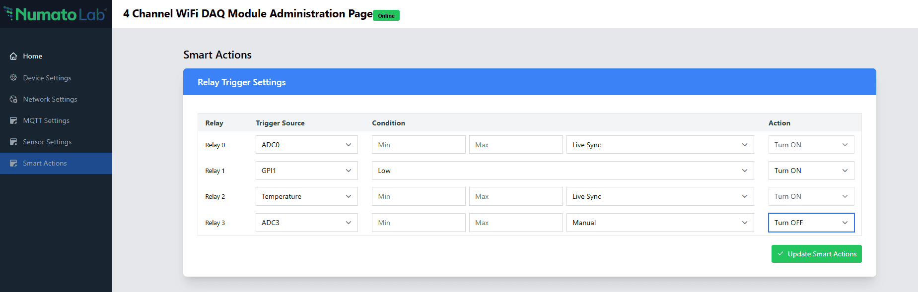
Smart Actions
The Smart Actions feature enables intelligent automation by allowing each relay on the device to respond dynamically to real-time input signals such as Digital Inputs (GPIOs), Analog Inputs (ADCs), and Temperature readings. This functionality is ideal for creating responsive systems that operate based on environmental conditions or external triggers, without requiring constant manual intervention.
Relay Trigger Settings
Each of the 4 relays (Relay 0 to Relay 3) can be independently configured to respond to corresponding input channels.
| Relay | Trigger Sources | Available Actions |
|---|---|---|
| Relay 0 | GPIO 0, ADC 0, Temperature | Trigger ON/OFF based on: GPIO 0 input level (LOW/HIGH) ADC 0 value in Min/Max range Temperature in °C range |
| Relay 1 | GPIO 1, ADC 1, Temperature | Trigger ON/OFF based on: GPIO 1 input level (LOW/HIGH) ADC 1 value in Min/Max range Temperature in °C range |
| Relay 2 | GPIO 2, ADC 2, Temperature | Trigger ON/OFF based on: GPIO 2 input level (LOW/HIGH) ADC 2 value in Min/Max range Temperature in °C range |
| Relay 3 | GPIO 3, ADC 3, Temperature | Trigger ON/OFF based on: GPIO 3 input level (LOW/HIGH) ADC 3 value in Min/Max range Temperature in °C range |
Modes of Operation
Manual Mode:
In this mode, the relay is triggered only once based on the condition defined. That is, if the input value falls within the specified range, the configured action (turn ON or OFF) will be executed and will remain in the same state.
Live Sync Mode:
This is a continuous monitoring mode that ensures the relay’s state always reflects the live input value. The relay will be automatically turn ON whenever the input value is within the specified range and automatically turned OFF when it goes outside the range.
FAQ
Q. I need a customized version of this product, can Numato do the customization for me?
A. Yes, we can definitely do customization but there may be minimum order requirements depending on the level of customization required. Please write to sales@numato.com for a quote.
Q. Where can I buy this product?
A. All Numato products can be ordered directly from our web store http://www.numato.com. We accept major credit cards and Paypal and ship to almost all countries with a few exceptions. We do have distributors in many countries where you can place your order. Please find the current list of distributors here.