
Introduction
Numato Lab’s 3 Channel Ethernet Relay Module is a versatile product for controlling electrical and electronic devices remotely from a PC over an Ethernet link. Ease of use and wider operating system compatibility are the primary goals behind this product’s design. This simplicity allows the use of off-the-shelf Terminal Emulation programs such as HyperTerminal and TeraTerm for controlling the module with a simple set of human-readable commands through a Telnet, HTTP, or web page. For power users, this module can be controlled by writing programs in various programming languages.
Applications
- Home Automation
- Lighting Control
- Garden Equipment Control
- Industrial Automation
- Test Fixtures
- DIY and Hobby
Board Features
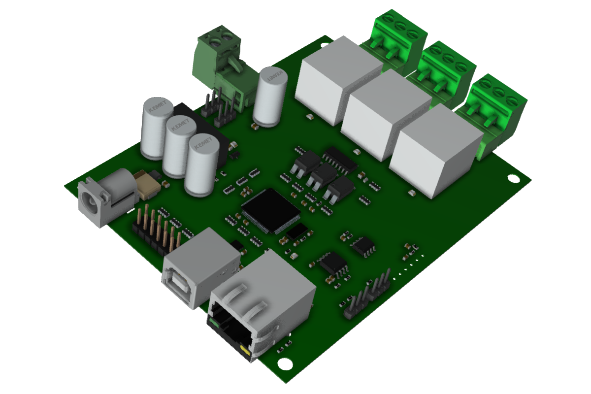
- 3 Relays with individual LEDs for status
- 10A Maximum Switching Current
- 10 TTL (3.3V) Compatible GPIOs.
- 10 Analog Input Channels (Multiplexed with GPIOs) with 10-Bit Resolution.
- Password-protected Web console, HTTP and Telnet communication interface
- LED indication for Power and individual relay status
Technical Specifications
| Parameter * | Value | Unit |
|---|---|---|
| Number of Relays | 3 | |
| Number of GPIO's | 10 | |
| Number of analog inputs (Multiplexed with GPIO's) | 10 | |
| Digital circuit power supply voltage (external) | 24 | V |
| Maximum current drawn by digital circuitry | 600 | mA |
| Relay Specifications | ||
| Nominal relay coil voltage | 24 | V |
| Nominal coil power consumption (per relay) | 360 | mW |
| Relay contact material | Silver Alloy | |
| Contact rating | 1C: 7A 240VAC/ 10A 120VAC | |
| Maximum switching voltage | 250VAC/ 30VDC | |
| Maximum switching current | 10 | A |
| Maximum switching power | 100 Min at 6VDC 1A | mΩ |
| Life expectancy (Electrical) | 100,000 | Operations |
| Life expectancy (Mechanical) | 10,000,000 | Operations |
| Nominal insulation resistance | 100 Min at 500VDC | MΩ |
| Maximum switching on response time | 10 | mS |
| Maximum switching off response time | 5 | mS |
| IO Specifications | ||
| Maximum IO source current | IO0 – IO9 | 2mA |
| Maximum IO sink current | IO0 – IO9 | 2mA |
| GPIO input low voltage | 0.15 | V |
| GPIO input high voltage | 3.3 | V |
| GPIO output low voltage | 0 | V |
| GPIO output high voltage | 3.3 | V |
| ADC Specifications | ||
| Resolution | 10 | bits |
| Full scale range | 0 – VDD | V |
| Reference voltage | VDD | V |
| Recommended Impedance of Analog Voltage Source | 2.5 | KΩ |
How to use 3 Channel Ethernet Relay Module
The following section describes how to use this module.
Components/Tools required
Along with the module, you may need the items in the list below for easy and fast installation.
1. CAT 5e Ethernet Cable(Straight through cable)
2. 24V 1A DC power supply
3. Medium size Philips screwdriver
Connection Details
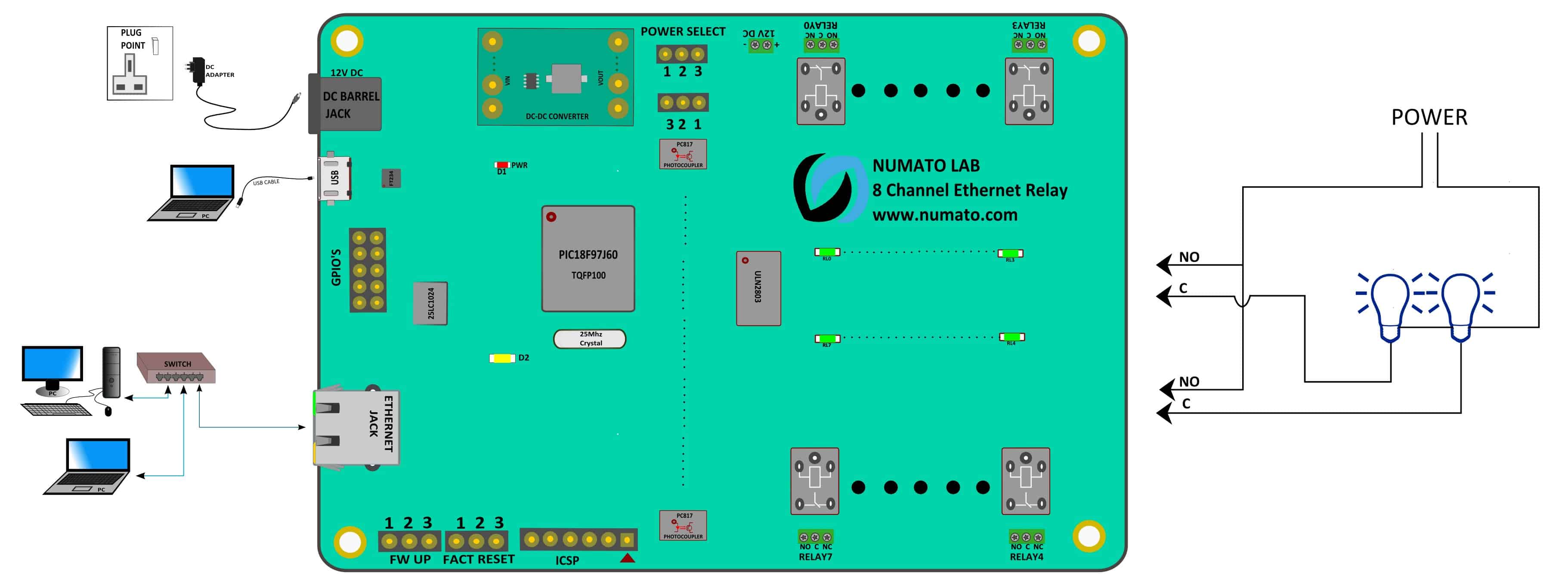 The above image shows the basic connection diagram that can be used in most of the situations. The connection diagram is the same for both AC and DC loads. Please make sure to use a freewheeling diode or snubber circuit if the load is inductive. More details about using inductive loads are available elsewhere in this document. Use a Straight Through Ethernet cable for communication when connecting the board to a switch or router. A Crossover Ethernet Cable may be required in some situations if connecting directly to a PC/Laptop port.
It is important to make sure that the wires used to connect loads are sufficiently rated to handle the expected load current. Exercise caution while working with high voltages. Short circuits can cause damage to the module and the PC. The following sections identify individual connections in detail.
USB Interface
The onboard USB Interface helps to communicate and configure this module seamlessly. This module detects as COM port and the user can configure the module using any serial emulator program like hyper terminal, TeraTerm, etc. Use FTDI drivers for the USB COM port device.
Use a USB A to USB B cable to connect to a PC. Please visit numato.com to buy cables and accessories for this product.
Ethernet Interface
 The onboard Ethernet port supports Ethernet 10 Mbps transmission speed that helps a computer to communicate and control this module easily.
You can connect the module to Local Area Network(LAN) via a common straight-through Ethernet cable.
Eg: Connecting the module to a switch in a network.
Relay Contacts
All contacts on each relay are available externally on screw terminals for easy user access. The relays are rated for AC and DC supply voltages. Please see the electrical parameter table for more details. Each relay has three contacts(C, NO, and NC). C is the common terminal and is used in both normally open and normally closed positions. The contacts NC and C wi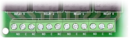 ll be connected when the relay is turned off and will be disconnected when the relay is turned on. And vice versa, the contacts C and NO will be disconnected when the relay is turned off and will be connected when the relay is turned on. The table below summarizes possible relay contact positions.
| Relay State | Connection between NC and C | Connection between NO and C |
|---|---|---|
| OFF | Close | Open |
| ON | Open | Close |
DC Power Supply
This module can be powered in two ways.
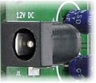 1. Use a 12/24V 1A DC power supply on DC jack(J1) on the Board for both logic circuit and relays (according to the relay coil voltage). Configure the Jumper on P16, P17 in POWER SELECT to 1-2 for using this way. Relays and logic circuits are not isolated from each other in this configuration.
2. Use a 12/24V 1A DC power supply for the logic circuit on J1 and a separate 12/24V 1A DC power supply for relays on P5 (according to the relay coil voltage). Configure the Jumper on P16, P17 in POWER SELECT to 2-3 for using this way.
With the first method, the board requires only one DC power supply to be fully functional. But  the relay section will not be isolated from the logic section. With the second method, the board requires two power supplies but the relay section will be isolated from the logic section as long as
 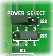 the two power supplies are galvanically isolated. Most off the shelf 24V DC power supply can be used for powering this Ethernet Relay Module. Make sure to connect the power supply with the correct polarity. Connect the positive terminal of the power supply to the +24 terminal on the module. Connect the negative terminal of the power supply to the GND terminal of the module. Connecting power supply incorrectly can cause damage to the module and/or other devices. Please refer to the marking on the board for more details.
Connecting power supply incorrectly can cause damage to the module and/or other devices.
Factory Reset
This Jumper is used to reset the settings onboard to factory defaults. To execute the factory reset, please follow the steps below.
- Power off the device.
- Configure the Jumper on P4 to 2-3.
- Power on the device.
- Wait for 10-15 sec until the LED D1 on board Blinks.
- Configure the Jumper on P4 back to 1-2.
- Power off the board and back on
Please use this feature only for recovering the User name / Password. This action will reset the User name, Password, Device ID, and other settings as well. After reset, the board can be accessed using the default User name and Password as shown in the table below
The factory default settings will be as below table.
| User name | admin |
| Password | admin |
| ID | 00000000 |
| Host Name | ETHR_A_003 |
| IP Address | DHCP Enabled |
Configure 3 Channel Ethernet Relay Module
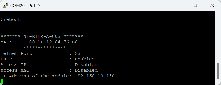
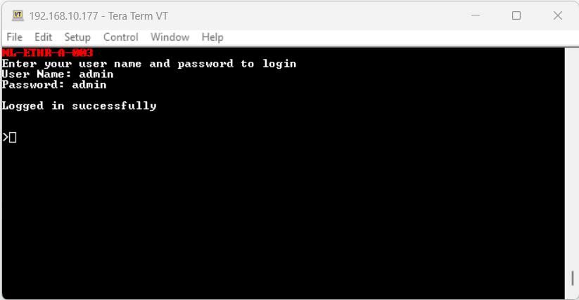
Connect a DC power supply and power up the device as mentioned DC Power Supply section above. A red LED (D1) will glow which indicates active power. For configuration over USB connect a USB A to B cable to the module also connect the module to a PC or a Switch/Router as mentioned in the Ethernet Interface section above. Run the hyper terminal program or any serial terminal program like PuTTY, TeraTerm, etc.
NB: By default, the module is configured with factory settings. To login to USB configuration settings, users need to send a ‘reboot’ command from telnet or do a factory reset.
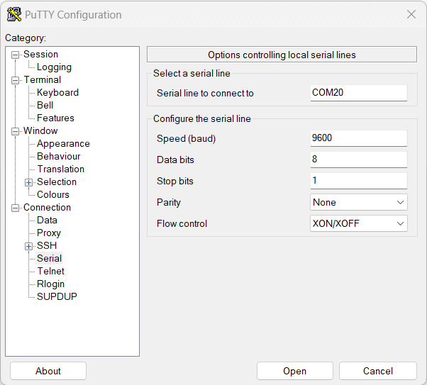
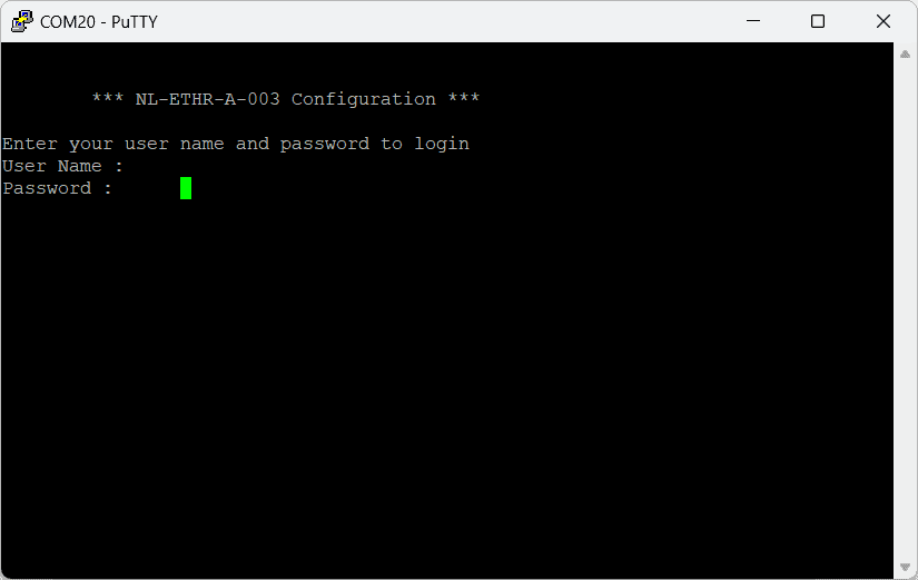
Select the module’s COM port and use the default settings similar to the below images and connect.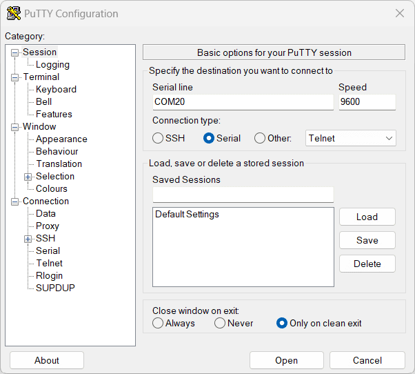
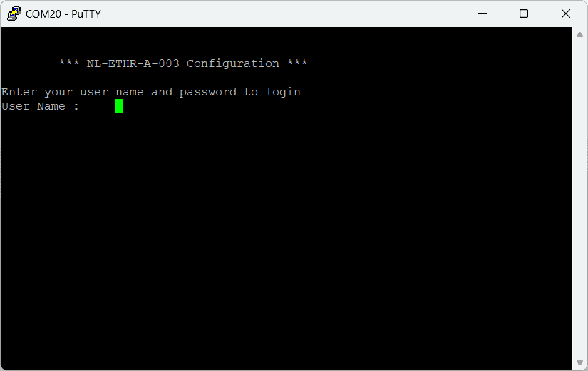
Users will be prompted to enter the User name and Password. The default User name and Password is ‘admin‘. You may change the User name and Password once logged in.
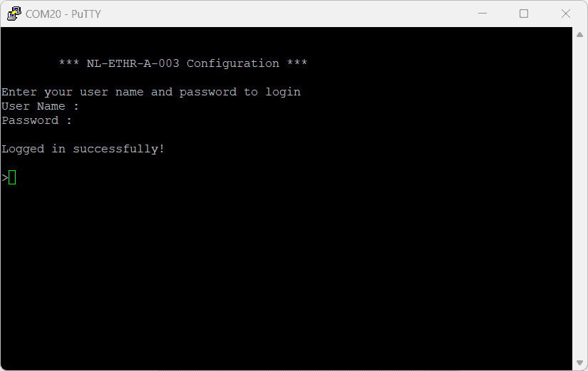
If the user name and password are correct, we will be able to see the login successfully message.
Configuration Command Set
| No. | Command | Example | Description |
|---|---|---|---|
| 1 | usr | usr set xxxxxxxx | Sets the new username for telnet, where x can be any alphanumeric character. The username can be 1-8 characters long. |
| usr get | Read the current username of telnet. The default username is "admin". | ||
| 2 | pass | pass set xxxxxxxx | Sets the new password for telnet, where x can be any alphanumeric character. The password can be 1-8 characters long. |
| pass get | Read the current password of telnet. The default password is "admin". | ||
| 3 | config usr | config usr set xxxxxxxx | Sets the new username for configuration over USB, where x can be any alphanumeric character. The username can be 1-8 characters long. |
| config usr get | Read the current username of configuration over USB. The default username is "admin". | ||
| 4 | config pass | config pass set xxxxxxxx | Sets the new password for configuration over USB, where x can be any alphanumeric character. The password can be 1-8 characters long. |
| config pass get | Read the current password for configuration over USB. The default password is "admin". | ||
| 5 | telnet | telnet auth on/off | Enable and disable the telnet authentication. telnet auth on enabling the telnet authentication and telnet off disabling the telnet authentication. |
| telnet auth get | Read the status of telnet authentication. | ||
| telnet port set xx | Sets the telnet port, where xx can be in the range of 00 to 99. The default value of telnet port is 23. |
||
| 6 | access | access ip on/off | Enable or disabling the IP based access to the module, this command adds filtering. Once the command is enabled, the stored IP using the access ip set command will be able to access the module. By default access IP is disabled. |
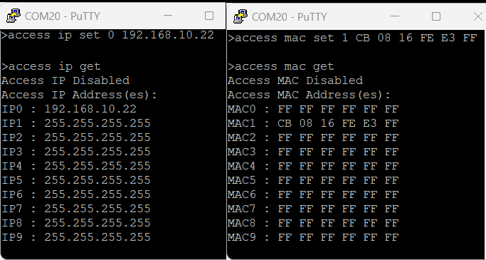
| access ip set N xxx.xxx.xxx.xxx | Set the acceptable IP in the network and save the same. Where N is the number 0-9, maximum 10 IP we can store in the non-volatile memory. Eg: access ip set 0 192.168.0. 2 |
||
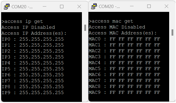
| access ip get | Read the stored IP in the memory. | ||
| access mac on/off | Enable or disabling the MAC-based access to the module, this command adds filtering. Once the command is enabled, the stored MAC using the access mac set command will be able to access the module. By default access MAC is disabled | ||
| access mac set N XX XX XX XX XX XX | Set the acceptable MAC in the network and save the same. Where N is the number 0-9, maximum 10 MAC we can store in the non-volatile memory. Eg: access mac set 0 D4 93 98 D2 4A 34 |
||
| access mac get | Reads the stored MAC in the memory. | ||
| 7 | dhcp | dhcp on/off | Enable or disable the DHCP of the module. |
| 8 | ip | ip set xxx.xxx.xxx.xxx | Sets the static IP to the module. Eg: ip set 192.168.5.48 |
| ip get | Read the status of DHCP and the static IP. If DHCP is enabled it will display the DHCP status and if it is disabled it will display the static IP too | ||
| 9 | mac id get | mac id get | Read the MAC id of the module. |
| 10 | reboot | reboot | Exit the configuration interface and enter to the application mode and start the telnet communication. |
The below table shows the new commands supported only in firmware version A0M03.01 and later.
| 11 | relay | relay poweron xx | Sets the relay power on value. relay poweron 03 : Turn OFF and ON relays on power-on the module according to the specified hexadecimal value. 0 – Turn OFF the relay, 1 – Turn ON the relay. '03' - 0000 0011 : Relays 0 and 1 will be turned on once entered to the telnet mode. xx can be in range 00-0F : 4 Channel Ethernet Solid State Relay xx can be in range 00-FF : 8 Channel Ethernet Solid State Relay |
| 12 | gpio | gpio poweron xxx XXX | Set the GPIO power-on value and direction. gpio poweron 1c5 28d – Sets GPIOs IO direction and status respectively at each bit position according to the bits of the specified hexadecimal value. IO direction: 0 – To set the GPIO as output mode & 1 – To set the GPIO as input mode. IO status: 0 - To clear the GPIO & 1 - To set the GPIO. '1c5 28d’- (0001 1100 0101) (0010 1000 1101): GPIOs 1,3,4,5,9 are set to output mode & GPIOs 0,2,6,7,8 are set as input mode. GPIO 0,2,3,7, and 9 are set to High GPIO 1,4,5,6, and 8 are set to Low. Thus once entered to telnet mode, GPIOs 1,4,5 will be outputs and low. GPIOs 3 and 9 will be outputs and high. All the other GPIOs will be inputs. xxx, XXX can be in range 000-3FF |
Configuration command Images
Example commands and results after executing the commands.
Powering Up 3 Channel Ethernet Relay Module
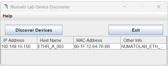
Connect a DC power supply and power up the device as mentioned in DC Power Supply section above. A red LED (D2) will glow which indicates active power. Connect the module to a Switch/Router as mentioned in the Ethernet Interface section above. Run Numato Lab Device Discoverer.jar, and click on Discover Devices. The window will display the IP address, Host Name, MAC Address, and Other information.
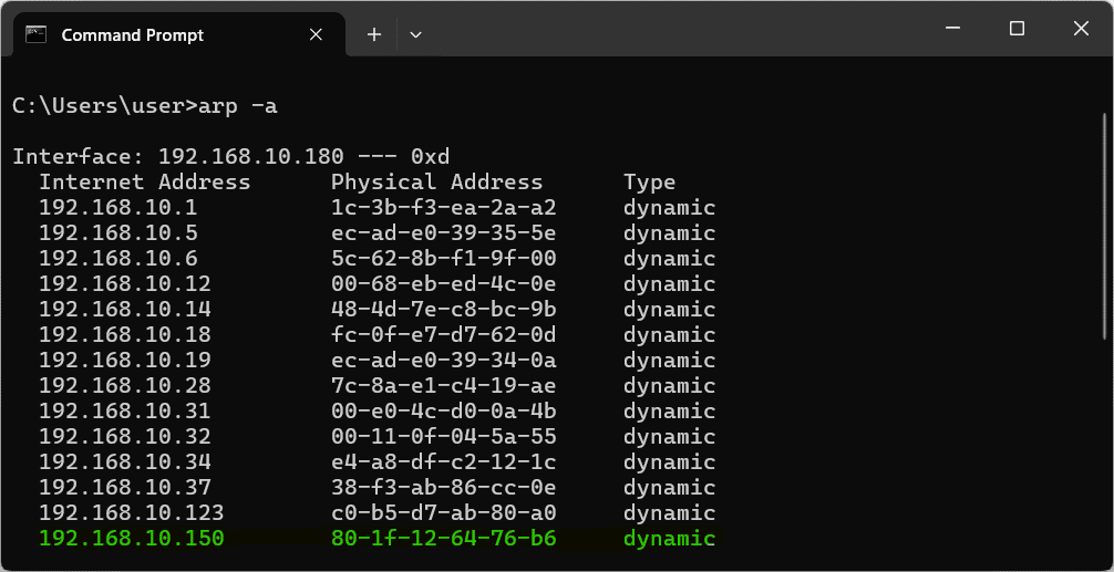
IP Address and MAC Address can be seen in the command prompt also, only after connecting the module through the web page. Open the command prompt and type the command ‘arp -a‘. This will display the available network interfaces and connected devices along with the MAC address and IP address of each device. Look for the IP address that corresponds to your device’s MAC address. The MAC address for each Relay Module is printed on a label on the board for your convenience. Use the IP address obtained in order to access the device.
Accessing the module
The module can be controlled by using one of the two interfaces below.
- Through HTML/Web Page served from the device.
- Through a Serial Terminal Emulator that supports TELNET (Eg: Hyper terminal, Teraterm, PUTTY…)
- Through HTTP commands
Accessing the module using web interface
The easiest method for controlling the module is through web page served from the device. To open the administration web page, type in the IP address in to the address bar of any web browser and press enter.
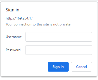
You will prompted to enter User name and Password. The default User name and Password is ‘admin’. You may change the User name and Password once logged in.
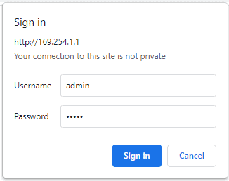
Enter the default User name and Password then click OK.
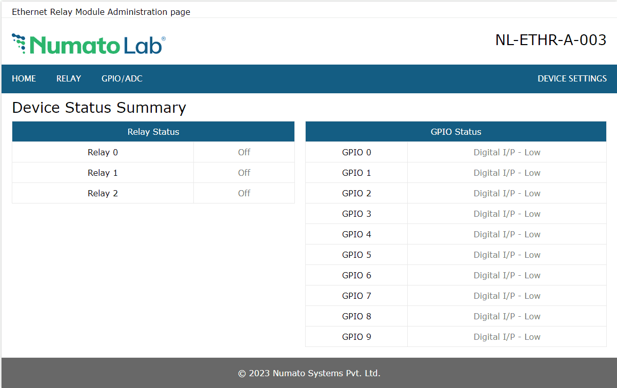
You will be presented with the device home page that shows the status of Relays and GPIOs
Relay Status and Control
There are 4 solid state relays on the board that can be controlled over Ethernet. Click on the RELAY link on the menu bar to access Relay configuration page. The Relay Index shows the corresponding relay on board. Relays on the board can be turned on/off by clicking the Toggle Relay button next to the corresponding relay index. The Status of the relays change automatically for easy identification.
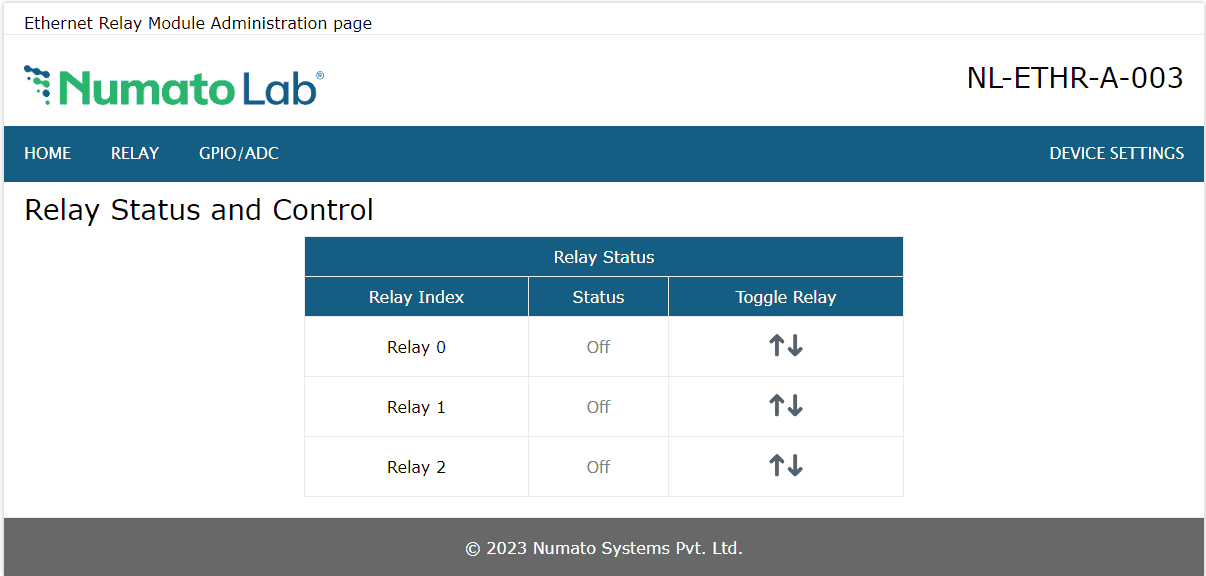
In the above image, we can see that Relay 0, and 2 are in ON position and rest of the relays are in off position. The status of the relay can be viewed on the home page as well
GPIO Status and Control
This board has 10 general purpose input/output’s each multiplexed with analog input. Click on the GPIO/ADC link on the menu bar to access Relay configuration page. The GPIOs can be turned on/off by clicking on the Toggle GPIO button next to the corresponding GPIO.
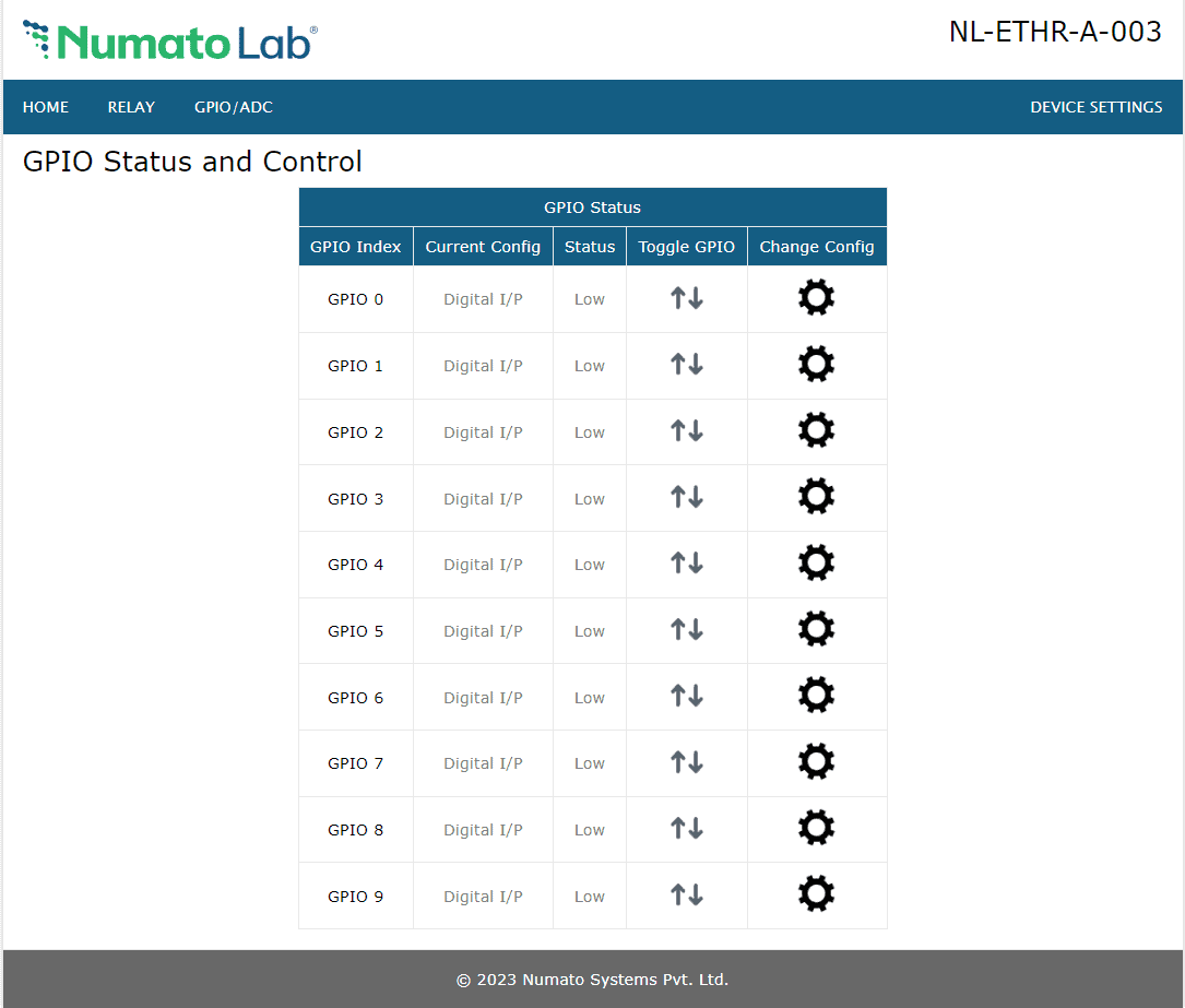
Individual GPIO can be configured in three modes.
- Digital Input(I/P)
- Digital Output(O/P)
- Analog Input
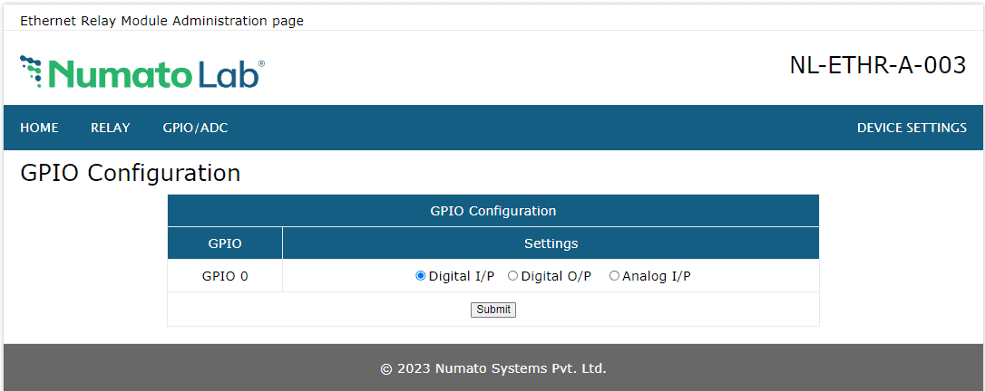
Digital Input(I/P)
To configure a GPIO as Digital Input, click on the corresponding GPIO’s Change Config button. Select Digital I/P radio and click the Submit button.
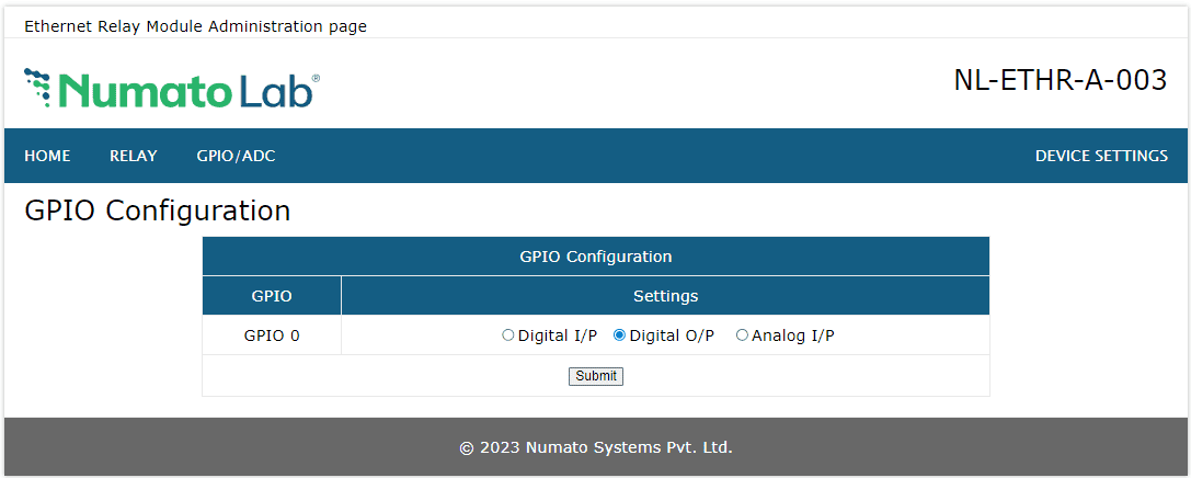
Digital Output(O/P)
To configure a GPIO as Digital Output, click on the corresponding GPIO’s Change Config button. Select Digital O/P radio and click the Submit button.
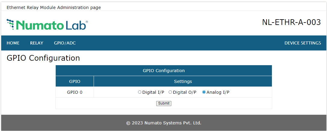
Analog Input (I/P)
To configure a GPIO as Analog Input, click on the corresponding GPIO’s Change Config button. Select Analog I/P radio and click the Submit button.
Individual GPIOs on the board can be turned on/off by clicking the Toggle GPIO button next to the corresponding index. The status change will be displayed on the page immediately for feedback.
 All GPIO pins can be used as Analog to Digital Converter inputs as well. The ADC input range is 0 to +3.3V. The ADC can acquire analog signal at the resolution of 10 bits per sample. It is recommended to use a series resistor with the GPIO/ADC pins when interfacing with other circuits. In output mode, GPIOs can source up to 2mA(Refer to Technical Specifications for more details).
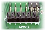
The table below summarizes the GPIO and Analog to Digital Converter input positions on the header.
Device Settings
Device Settings page displays the current firmware version, Device ID, Account Settings and Basic Network Settings. A logged-in user can change and save the Device ID, User name, Password and network settings.
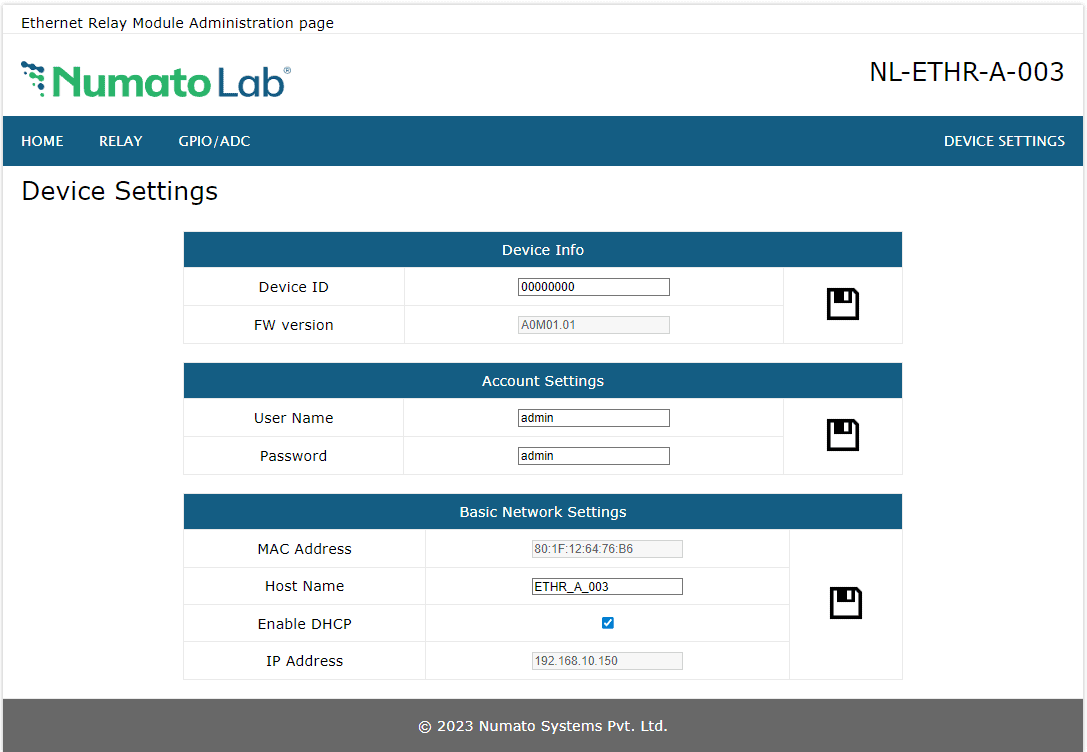
In the above image, the firmware version is displayed as A0M03.01, default device ID 00000000, default User name and Password as ‘admin’. The user can change and save the Device ID, User name and Password as explained in command set or changing the appropriate field on this page and clicking on the save button on the right side. The User name and Password can be reset to factory defaults via Factory Reset explained elsewhere in this document. The Basic Network Settings Shows the Device MAC address, Host Name, and IP Address. The default hostname and IP Address can also be changed according to the user’s wish. After saving changes the board will reboot with the new network settings.
Controlling the module through TELNET interface
-
The simple set of ASCII based human readable command sets supported by this module makes controlling relays easy via TELNET protocol very easy. The following sections give examples of how to use the module with PuTTY and TeraTerm.
To use this module with PuTTY, please follow the steps below.
- Connect the module to the LAN.
- Open PuTTY and enter the IP address corresponding to the module, leaving the port number as 23.
- Click Open.
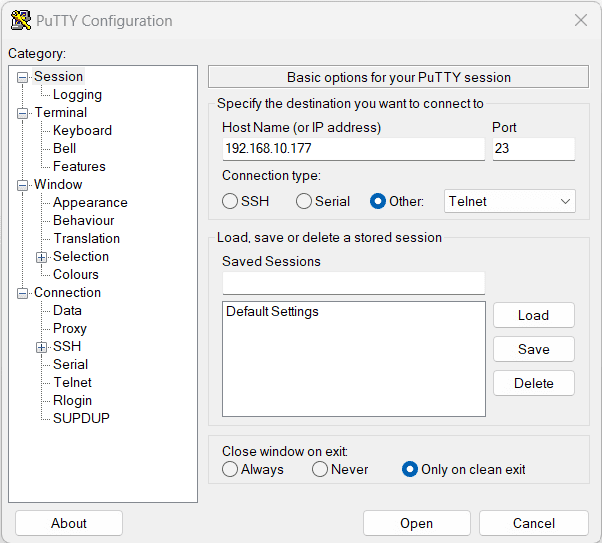
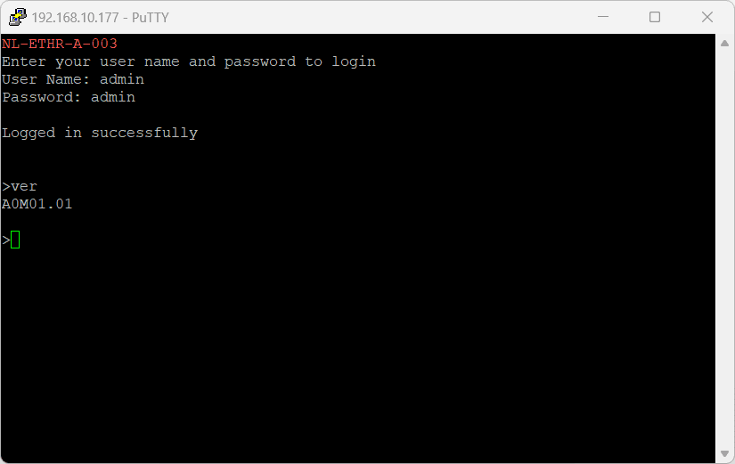
- If everything goes well, you should be presented with a screen as below.
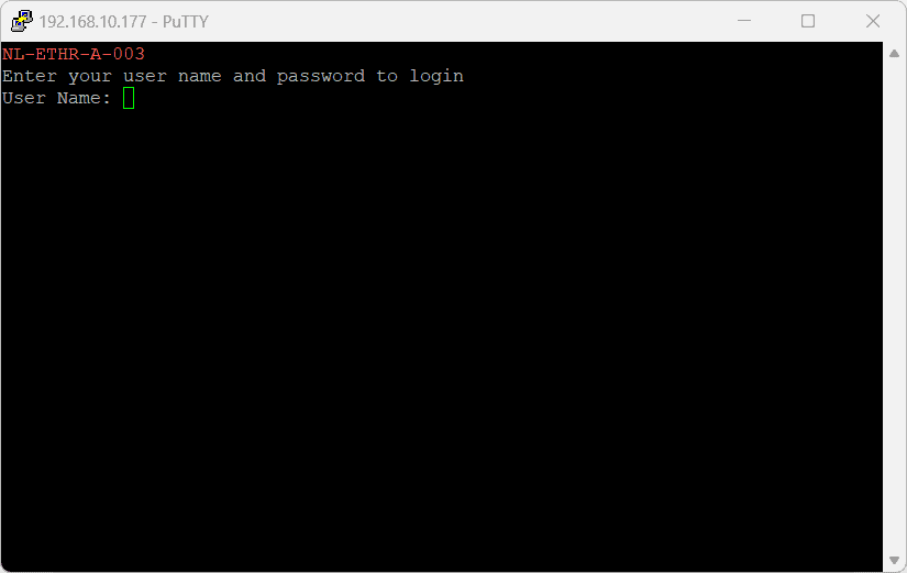
- Type in the TELNET User name and Password when asked and press enter key.
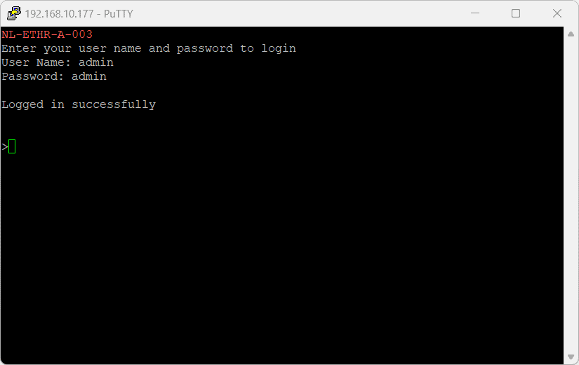
- Commands listed in the table in section “Sending Commands” can be entered here now. For example, here is the response for “ver” command.
Using the relay module with TeraTerm is just as easy. Please follow the steps below.
TeraTerm is an open source software. A free copy can be downloaded from http://en.sourceforge.jp/projects/ttssh2/releases/
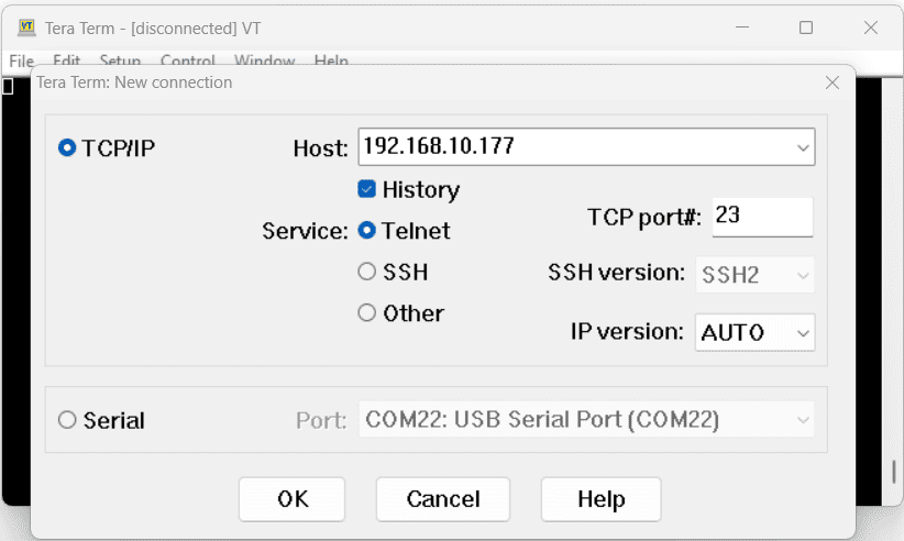
- Run TeraTerm and type in the IP address corresponding to the module in the “New connection” dialog and click OK.
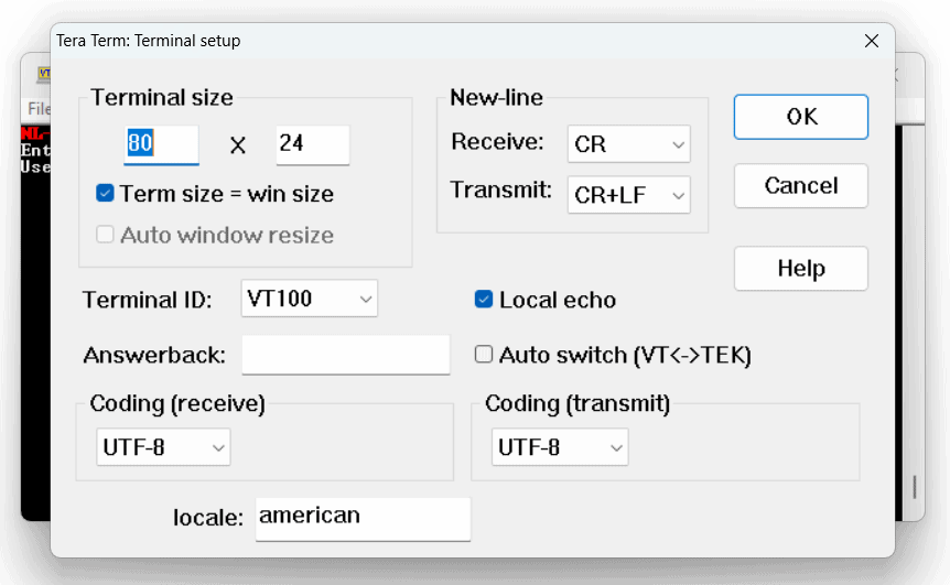
- Then select the terminal setup from the setup button and make sure the settings are as shown below, and press OK.
- Type the User name and Password when asked.
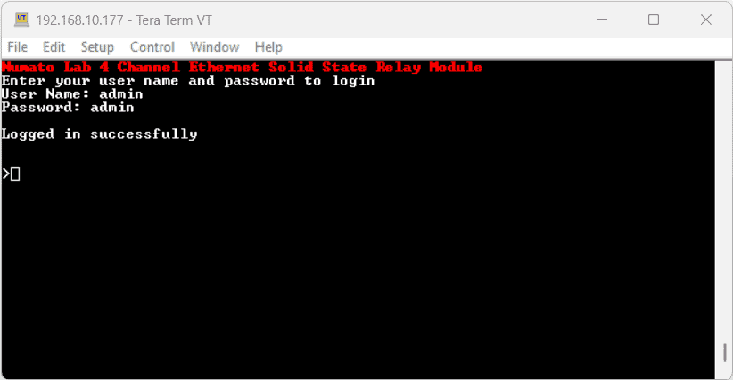
- Press ENTER key and the command prompt should appear. Commands listed in the table in section “Sending Commands” can be entered here now. For example, here is the response for “ver” command.
Sending Commands
One of the most powerful features of this module is the simple easy to use command set it supports. This command set allows for a very simple interface to access the features of the module through the TELNET protocol. The following sections give details of the command set and how to use the command set.
The command set
This product supports a very simple command set that is designed to be less cryptic and easy to use manually (using terminal emulation programs that support TELNET) or through a program written in one of the many supported languages
List of currently supported commands.
| No. | Command | Parameters | Example | Description |
|---|---|---|---|---|
| 1 | ver | None | ver | Returns firmware Version |
| 2 | id | get/set xxxxxxxx | id get, id set 12345678 | Reads/Sets id of the module |
| 3 | usr | get/set xxxxxxxx | usr get, usr set admin | Reads/Sets User name |
| 4 | pass | get/set xxxxxxxx | pass get, pass set admin | Reads/Sets Password |
| 5 | relay | on/off/read, relay number readall writeall/poweron , value | relay on 000, relay off 000, relay read 000, relay readall, relay writeall 07 relay poweron 03 | Relay control |
| 6 | reset | None | reset | Reset relays to default state (all relays turned off) |
| 7 | adc | read, channel | adc read 000 | Read Analog to Digital Converter input |
| 8 | gpio | set/clear/read/status, gpio number. poweron , io direction , value | gpio set 000, gpio status 000, gpio poweron 000 3ff | Control General Purpose Input/Output |
| 9 | info | None | info | Display information about the module including GPIO and Relay power-on status. |
| 10 | reboot | None | reboot | Exit the application mode and enter to the configuration interface and start the configuration via USB and vice versa. |
The table below has more detailed information about available commands.
| No. | Command | Example | Description |
|---|---|---|---|
| 1 | ver | ver | Returns current firmware version. |
| 2 | id | id get id set xxxxxxxx | Id get reads the module ID. Id set will assign a new ID to the module. “x” stands for alphanumeric characters including symbols. The new ID must be exactly 8 characters in length. |
| 3 | usr | usr get usr set xxxxxxxx | usr get reads the default User name. usr set will assign a new usr name to the module. “x” stands for alphanumeric characters including symbols. The new User name can be 1 – 8 characters length. |
| 4 | pass | pass get pass set xxxxxxxx | pass get reads the default Password. pass set will assign a new Password to the module. “x” stands for alphanumeric characters including symbols. The new Password can be 1 – 8 characters length. |
| 5 | relay | relay on xxx | Turn on the relay ‘xxx’. relay on 000 – Turn on Relay 0 xxx can be 000 to 002 |
| relay off xxx | Turn off the relay ‘’xxx’. relay off 000 – Turn off Relay 0 xxx can be 000 to 002 |
||
| relay read xxx | Read status of the relay ‘xxx’. relay read 000 – Read status of Relay 0 and print either ‘on’ or ‘off’ depending on the status xxx can be 000 to 002 |
||
| relay readall | Reads the status of all relays in a single operation. The return value will a hexadecimal number with binary value 1 at bit positions for relays in ON state and 0 for relays in OFF state. Eg: a return value 00 (binary 0000 0000) means all relays are OFF. A value 07(binary 0000 0111) means all relays are ON relay readall – Returns status of all relays |
||
| relay writeall xx | Control all relays in a single operation. A hexadecimal value must be specified with desired bit positions set to 0 or 1. A value 0 at a bit position will turn off the corresponding relay. A value 1 at a bit position will turn on the corresponding relay. relay writeall 07 – Turns on all relays xx can be 00 to 07 |
||
| relay poweron xx | Sets the relay status on power-on. Turn OFF and ON relays on power-on the module according to the specified hexadecimal value. 0 – Turn OFF the relay , 1 – Turn ON the relay. xx can be 00 to 07 |
||
| 6 | reset | reset | Resets all relays to off state which is the default state. GPIOs are not by affected by the command. |
| 7 | adc | adc read xxx | Reads the analog voltage present at the ADC input ‘xxx’ mentioned. adc read 002 – Reads value of adc input 2 and print the response. The response will be a number that ranges from 0 – 1023. xxx can be 000 to 002 |
| 8 | gpio | gpio set xxx | Set GPIO ‘xxx’ output status to high. gpio set 000 – Sets O0 to high state xxx can be 000 to 009 |
| gpio clear xxx | Sets GPIO ‘xxx’ output status to low. gpio clear 000 – Sets O0 to low state xxx can be 000 to 009 |
||
| gpio read xxx | Read status of the GPIO ‘xxx’. gpio read 004 – Read status of I0 and print either ‘1’ or ‘0’ depending on the status. xxx can be 000 to 009 |
||
| gpio status xxx | Read the GPIO status present at ‘xxx’ without changing the GPIO direction. gpio status 003 – Read status of O3 and print either ‘1’ or ‘0’ depending on the status xxx can be 000 to 003 |
||
| gpio poweron xxx XXX | Sets the GPIO status on power-on according to the hexadecimal value and IO direction mentioned. xxx – GPIO direction [0 – output, 1 – input] XXX –poweron value [0 – Clear GPIO, 1- Set GPIO] gpio poweron 00f 05d ‘00f’ ‘05d’ – 0000 0000 1111 0000 0101 1101 GPIOs 0 to 3 – input GPIOs 4 to 9 – output Set GPIOs 0,2,3,4&6, Clear GPIOs 1,57,8&9 |
||
| 9 | info | info | Displays the information on GPIO power-on status |
| 10 | reboot | reboot | Exit the application mode and enter to the configuration interface and start the configuration via USB and vice versa. |
Controlling through HTTP commands
This module supports HTTP commands.
Refer to the ‘HTTP Command Set‘ knowledge base to know more.
Below are some of the images related to controlling this module through HTTP commands.
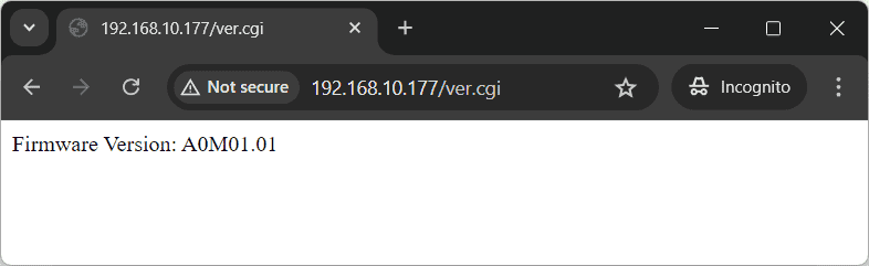
fig 1: Displays firmware version
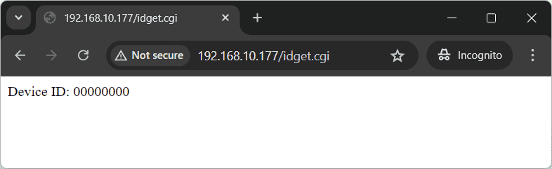
fig 2: Displays device ID
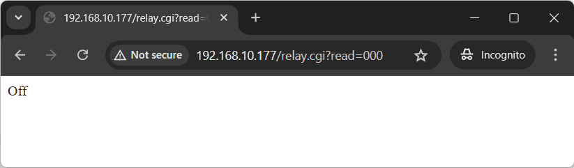
fig 3: Read relay 0 status
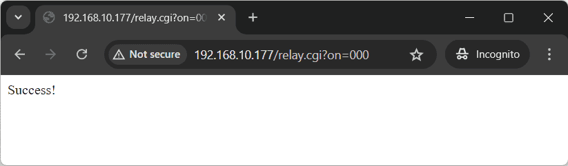
fig 4: Turn on relay 0
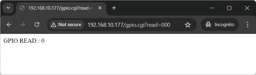
fig 5: Read GPIO 0 status
Additional Information
Analog to Digital Converter
4 Channel Ethernet Solid State Relay Module does support Analog to Digital Conversion on some of the IO terminals. A list of GPIO’s that supports analog function in this product is listed elsewhere in this document. There is no special command is required to execute to switch between analog and digital mode. Executing the “adc” command will set the GPIO to the analog mode and executing the “gpio” command will set the GPIO back to digital mode on the fly. The resolution of the ADC is 10 bits unless otherwise noted. The input voltage range of the ADC is 0 – VDD (this product uses 3.3V power supply, so the range will be 0 – 3.3V). The result will be returned as a number starting at zero and ending at 1023. Zero indicates zero volts at the ADC input and 1023 indicates VDD (3.3V for this product) at ADC input.
Using GPIO's with switches
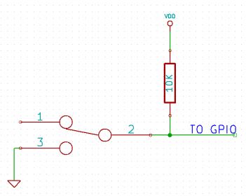 It is possible to read the position of a switch that is connected to a GPIO. An SPST or SPDT switch is recommended to use with GPIO’s. Push switches do maintain the contacts closed only for a very short time so using them is discouraged. The fundamental idea of using a switch with GPIO is to have the switch cause a voltage level change at the GPIO pin when pressed. Usually, this is achieved by using an external pull-up resistor along with the switch. The pull up resistor is connected between the GPIO and VDD and the switch is connected between the GPIO and ground. When the switch is not pressed, the pull-up resistor will cause the GPIO to stay at the VDD voltage level. When the switch is pressed, the GPIO is short-circuited to ground and stays at zero voltage. This change in voltage and thus the position of the switch can be read using the “gpio read” command. Please see the recommended connection diagram below.
Using relay modules with inductive loads
It is important to take additional care when using relays with inductive loads. An inductive load is pretty much anything that has a coil and works based on magnetic principles like Motors, Solenoids, and transformers. Inductive loads produce back emf when the magnitude of the load current changes. The back emf can be in the order of tens or even hundreds of voltage (See this Wikipedia article http://en.wikipedia.org/wiki/Counter-electromotive_force). This effect is most severe when power is disconnected from the inductive load because the rate of change of current is maximum at that point. Even though the back emf lives only for a very short time (a few milliseconds) it can cause sparks between the relay contacts and can deteriorate the contact quality over time and reduce the life span for the relays considerably.
So it is important to take countermeasures to suppress the back emf to acceptable levels to protect relay contacts. 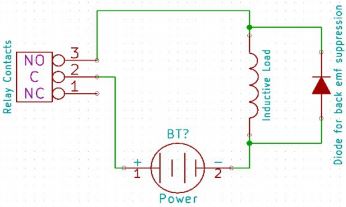 Usually, this requires connecting electronic devices in parallel with the load such that they absorb the high voltage components generated by the load. For solenoids, connecting a diode (fast switching diode is recommended) in parallel to the load (in reverse direction to the load current) is very effective. A diode used for this purpose is usually called a freewheeling diode. Please see the diagram on the right for connection details.
A capacitor with a proper rating is recommended for protecting the relay contacts when a motor is used as a load. The capacitor should be rated enough to withstand the back emf that is generated by the motor. Please see the diagram below for connection details.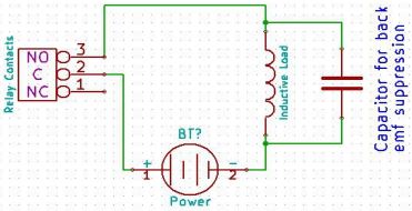
Please note that the relay modules are NOT shipped with back emf suppression devices pre-installed. The exact kind of suppression device and the parameters of the selected device can vary depending on the load itself. Some of the parameters that affect the suppression device selection are the inductance of the load, power supply voltage, load current, physical size/structure of the load, etc.. It is obvious that it is impossible for us to predict these parameters and design required back emf suppression device and incorporate that on the board. So we believe this is a task best left to the module user. There is an excellent article on designing back emf suppression on Wikipedia at http://en.wikipedia.org/wiki/Flyback_diode
FAQ
Q. What is the connector marked as ICSP on this module?
A. This connector is used to program the on-board microcontroller. This connector is primarily intended for factory use.
Q. I need a customized version of this product, can Numato do the customization for me?
A. Yes, we can definitely do customization but there may be minimum order requirements depending on the level of customization required. Please write to sales@numato.com for a quote.
Q. Where can I buy this product?
A. All Numato products can be ordered directly from our web store http://www.numato.com. We accept major credit cards and Paypal and ship to almost all countries with a few exceptions. We do have distributors in many countries where you can place your order. Please find the current list of distributors here.